Connecting a pressure switch to a pump without a hydraulic accumulator. Pressure switch for a hydraulic accumulator: how to install and configure it correctly
We will send the material to you by e-mail
All constituent elements of an autonomous water supply station must work in concert. In this case, the efficiency provided by the equipment manufacturer will be ensured. Proper installation and configuration for the accumulator will also reduce negative impacts on equipment. This will extend its service life without additional costs. Own knowledge and skills will help to personally carry out work operations, without resorting to the services of specialized service companies.
The design of the device for the accumulator
For a better understanding of the functions individual elements we need to consider the system as a whole.
From a well, or other source, water is pumped into the main pipeline by a pump. To exclude its movement in the opposite direction, a safety valve. Shut-off valves are installed in the right places. It is used for preventive maintenance, adjustment, replacement of failed units.
Water through the pipeline enters a special container, which performs several functions:
- accumulation and storage of a stock of liquid;
- creation normal pressure in sections of the pipeline connected to consumers;
- damping of pressure drops when connecting local water supply to centralized networks.

The main working element of such a container is a flexible partition. But the initial pressure in the tank itself is created by the pump. With appropriate equipment, it is controlled from a special remote control. Data is received there from the pressure switch for the accumulator.
Above is part of the class diagram " smart House". It is connected to the general control system. In practice, more economical solutions are often used.
To successfully solve the indicated tasks, the following designs of hydraulic accumulators are used:
- A strong tank is created with elements that are useful for firmly fixing on a horizontal or vertical plane.
- Metal cases are protected by special coatings against corrosion. They are designed for pressure up to 6 atm. and higher.
- A rubber membrane is inserted inside.

- For adjustments and adding and releasing air, a built-in spool is used. V large capacities install a special valve.
- To improve consumer characteristics, a layer of enamel, ceramics and other chemically neutral compounds is created inside the tank. For systems with drinking water use completely safe grades of rubber.
Note! If a hydraulic accumulator is purchased for a heating system, attention should be paid to the suitability of the model for working with liquids at elevated temperatures.

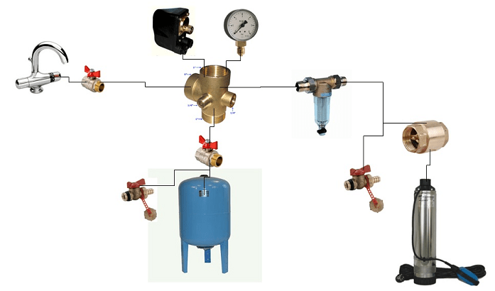
This picture shows another important element, the flow filter . It prevents the ingress of mechanical impurities, damage to the relay and blocking of its drive mechanisms. The increased capacity of the tank is useful not only for large daily consumption. It will reduce the number of on / off pumps, which will have a positive effect on the durability and reliability of the system.
The standard method for calculating tank volume (OB) uses the following formula:
ABOUT \u003d 16.5 x RV / KV x KD x 1 / DVK, where:
- RV- consumption in liters per minute. They use the sum of all needs, household, for cooking, sanitary and hygienic and others.
- HF- the number of inclusions of the injection pump in 60 minutes. It is recommended to select the parameters in such a way that the number of such starts does not exceed 8-10 for the corresponding period of time at maximum consumption.
- KD is the complex pressure coefficient. It is calculated according to the formula Dvk x Dvyk / (Dvk - Dvyk). Here, Dvk and Dvyk are the levels of maximum and minimum pressure, according to which the pump is turned on and off.
- DVK- this is the pressure that is formed in the part of the tank where the air damper is located.
In order not to embarrass yourself year-round living for a family of three, a tank with a capacity of 40-60 liters is sufficient. Such advice is given by specialized experts. In fact, it is better to make a more accurate calculation with the above method. The results obtained should be increased taking into account the visits of guests, other situations accompanied by increased water consumption. A similar approach will help to purchase a hydraulic accumulator for water supply, the price of which will correspond technical specifications and the needs of future users.
When placing the tank at the highest point of the building, the force of gravity will be used. But it must be borne in mind that the room must be reliably protected from adverse external influences. It maintains a temperature above 0 ° C all year round.

It is necessary to remember about the increase in mechanical loads. A large water tank weighs a lot, so sometimes additional reinforcement of the power frame of the building is required. For these reasons, large containers are often installed in the basement.

Related article:
How to install a pressure switch for a hydraulic accumulator
Before carrying out work operations, it is necessary to clarify the general requirements. To function in optimal mode the pressure difference for turning the pump on and off is set within the range from 0.9 to 1.8 atm. Exceeding it will increase power consumption.
To calculate what pressure should be in the accumulator (DGA), use the formula DHA \u003d (B + 6.5) / 10, where:
- V- height. This distance is taken from the central axis of the tank to the uppermost point at which water is taken.
- 6,5 - this digital coefficient takes into account the height of a particular building. For example, a typical cottage (2 floors) is taken.

Note! In the absence of standard equipment, an appropriate measuring device will be required.
The process of connecting the pressure switch to the accumulator
For study in this article, a mechanical pressure switch for a hydraulic accumulator is considered. This design is repeated in modifications from different manufacturers, with relatively minor changes.

This product is connected to the water supply system in assembled form. For accommodation in convenient location flexible tubing rated for appropriate pressure levels may be used. If necessary, use transition fittings. Upon completion of the installation, the tightness of the threaded connections is experimentally checked.

The electrical connection may be made directly in the power supply circuit of the pump. Use wires rated for the appropriate power. To eliminate errors, it is recommended to use products with a color braid. The ground standard is a combination of yellow and green. The electric motor is connected to the 220 V network through a machine that provides quick shutdown in the event of a short circuit.

Everything electric installation work performed with power off. Accidental voltage supply should also be excluded during the adjustment of the pressure switch for the accumulator.

Wiring diagram when using a dry running sensor
Setting the accumulator pressure switch
Use the following algorithm:
- Turn off the pump and remove the water.
- Turn on the equipment and increase the pressure, followed by draining the fluid. Record the motor on/off levels.
- Increase the threshold at which voltage is applied to the engine with a nut on a large spring (clamp it).

Before installing a hydraulic accumulator, you need to read the recommendations of specialists A hydraulic accumulator is needed to create pressure, store water, which will be useful to guests in the house in the event of a power outage, and reduce water hammer in networks at their summer cottage. The device looks like an ordinary tank with a mechanism for creating pressure.
- The process of connecting the accumulator
- Is it easy to install a hydraulic accumulator
- Is it possible to make a hydraulic accumulator with your own hands
- We disassemble how to connect a hydraulic accumulator to a submersible pump
- What is a hydraulic accumulator connection diagram
- How to connect a hydraulic accumulator for water supply systems (video)
If the accumulator is correctly connected, then everything further Maintenance you can do it yourself. Therefore, connect this device correctly so that you do not suffer later during its operation.
To connect the accumulator, you must use check valve. The battery tank is connected to a submersible pump, so the valve will not allow water to flow. You can also choose a deep-well pump of the Gileks brand, which can be lowered to the bottom of a well or well. Of course, there are other types of pumps. After all, the pumping apparatus is also capable of pumping air for pumping station. Let's analyze the usual case of mounting a hydraulic accumulator.
 When connected, the accumulator must be disconnected from the outlet
Hydraulic accumulator connection mechanism:
- We measure the dimensions of the accumulator;
- We get the scheme of pipes for water supply and heating;
- Are looking for free place for installation according to dimensions;
- Of the options found for installation, leave the place that is closest to the pump;
- We connect the submersible pump to the accumulator.
Thus, you will calculate the place for installing the accumulator.
Remember that the water pump must be lowered below the level of the water table by no more than 30 centimeters.
The device must be located as close as possible to the water pump. As a rule, the batteries in this case are located at the entrance to country house. In order to subsequently service the accumulator, it is necessary to calculate its integration into the system of cold and hot water. This need is associated with the discharge of water from the tank. Therefore, be careful about the installation site.
Is it easy to install a hydraulic accumulator
Summer residents immediately panic when they hear that the accumulator must be connected to the water supply system. They think that pipes can suddenly burst and then the whole country cottage area together with the house will be filled with water. This is not true.
The installation of the accumulator takes place according to the standard and proven scheme. A lot of summer residents integrated their tanks along it. And they did an excellent job. To do this, they purchased all the necessary components in the form of nipples, pumps and fittings.
In Denmark, Germany and Italy, hydraulic accumulators are installed in basements for 50-100 liters.
 One person is enough to install the accumulator
To put it in the right place, you need to determine the water flow parameter for the whole house. Determine the power of the pump and the volume of the accumulator. It is also worth knowing the location of the main water supply units.
- hoses;
- Pipes;
- Fitting;
- Nipples;
- Cranes and so on.
Then look at the installation diagram and just do everything as indicated there.
At first glance, it seems that installing a tank is difficult task. This is not true. Decide on a place, look at the schemes that the water supply has. Buy the connection parts and simply connect the tank to the general water supply.
Is it possible to make a hydraulic accumulator with your own hands
Many craftsmen make a hydraulic accumulator with their own hands. To make it yourself, you need to understand its device and design.
A hydraulic accumulator is a container with a certain volume. Its structure is quite simple and does not represent something complicated. The tank consists of only two main parts.
The structure of the tank is:
- membrane;
- Rubber pear.
 You can make a hydraulic accumulator yourself only if you have experience
For the tank, you can use a container made of plastic or aluminum. Inside the material of the tank must be smooth and even. If there are roughness in it, then the inner membrane or pear will simply stretch, which will lead to its destruction. There is also a membraneless accumulating tank in which there is no membrane. But such a tank is less efficient. The presence of one membrane expansion tank can solve many problems in water supply.
The tank should be chosen with a volume of more than 30 liters.
The tank will require a pressure switch and pressure gauge, which can be found at a modest price on the market. To connect, also take fittings, quarters, tees and a tap. In the store selling them, ask to pick up only high-quality models, because there are different form. As a pear or membrane, you can take a bicycle chamber - a nipple. You should also have a sheet of rubber and sealant.
In order not to buy a tank and save your money, you can make it yourself. To do this, it is enough to find a tank with a volume of more than 30 liters and components in the form of rubber sheets, fittings and tees with taps. So you will design a good tank for the water supply system.
We disassemble how to connect a hydraulic accumulator to a submersible pump
In order to properly connect the accumulator to the submersible pump, you first need to theoretically understand the connection mechanism. This will help to quickly complete the work of connecting the pump to the tank.
Connecting the accumulator to the water supply system is not difficult. To do this, it is enough to have everything necessary elements, valves, hoses and connect them sequentially according to the algorithm.
In order to connect the tank, it will be necessary to check the presence of:
- Downhole pump;
- Relay;
- Pipelines for the flow of water from the pump to the future tank and from the tank to water intake points;
- check valve;
- Stop valves;
- Filters for water purification;
- Drainage for sewerage.
 Pipes for connecting a hydraulic accumulator to a submersible pump are sold at any hardware store
Before installing the tank, check that all necessary tools and elements.
If you have all of the above, then you can start connecting. An adapter nipple is connected to the submersible pump. Next is the connection of the check valve and pipe. Then a fitting and a filter are placed, and a tap between them. After them, install the fiver and pressure switch. A manometer is required for control. It helps to set the pressure. Connect a drain valve and a hose to the accumulator that can withstand vibration during operation. This completes the installation. In this case, the well fades into the background, because all the main work is transferred to the home water supply system.
Summer residents sometimes install a container on the wall. To do this, put the tank on the mount.
Connecting the battery to the pump is not difficult. The main thing is to check the availability of all components for connecting to a submersible or for well pump. Otherwise, you will have to turn off the work. The connection process can only take a couple of hours if you do it in the correct sequence.
What is a hydraulic accumulator connection diagram
In order for the connection to be successful, it must be done according to the scheme. Learn what you need to connect, what elements and parts, and also, the instructions and connection diagram will help you.
To know what and where to connect, you must first familiarize yourself with the main components of the connection diagram. The whole process is built around them. The purpose of the diagram is to show how the accumulator is connected in a common circuit.
The accumulator connection diagram has three main elements:
- The accumulator itself;
- Submersible pump;
- Pressure switch;
- Five pin fitting.
 The hydraulic accumulator connection diagram can be easily found on the Internet and printed on a printer
These are the main components of the connection scheme. When assembling the hydrobox, take into account the automatics of the hydraulic tank, put a connection to the hoses and an additional fitting if necessary, the piping will also help in reliability. It is better to connect the hydraulic pump to the pressure switch in the last stages, so voltage is connected to it. The relay is connected to a five-pin fitting. A non-return valve is also attached to it.
Remember that the relay is supplied with 220 V AC power. Be careful!
A hydraulic accumulator is attached to the other end of the fitting. From it there is a pipeline to the house to the taps. A pressure gauge is used to analyze the condition. It can be installed on a five-pin fitting. Usually it already has holes for installation.
According to this scheme, you quickly and without problems connect all the main elements. Do not skimp on buying a good submersible pump and selecting a high-quality hydraulic accumulator. These are the things that are worth spending money on. In this case, they will serve you for decades.
How to connect a hydraulic accumulator for water supply systems (video)
A hydraulic accumulator for a water supply system is necessary if you want to have constant access to water in your home. It will adjust the pressure in the water supply network and give you the opportunity to enjoy clean water from the tap. A small container is easy to install, and there are many benefits from it for a private house. Buy a hydraulic accumulator and you will always have a constant supply of water in the house.
To find out which is stronger - a water hose, pipes or a pump, you can assemble a water supply system without a pressure switch. In all other cases, when water is supplied to the house, a device is built into the system that replaces the manual switching on and off of the supply voltage of the deep pump.
It is impossible to imagine an individual water supply at home without a relay that allows you to automatically turn off the pump as the water supply system is filled with water and turn it on after the water is used up.
Fig.1 Design of the pressure switch
Structurally, a standard pressure switch for pump control is as follows. Housed in a plastic case terminal blocks for connecting the power cable and a mechanical device control system with adjusting spring struts, outside there is a branch pipe with a diameter of 4 inches for connection to the water main. The supply cable enters and leaves the pressure switch through two wide inlets, the wires are clamped with a nut with a plastic ferrule.
Normally, the contacts are normally closed and the connected device powers the pump motor. With an increase in pressure in the system, water acts on a rubber membrane with a piston installed at the inlet of the water pipe of the device. In turn, the membrane piston presses on a movable metal platform pivotally fixed inside the device body at one point. The platform plate rises and opens the electrical contacts; when the pressure drops, it returns to its original state, closing the contacts.
A screw with a spring and a nut is installed in the center of the device, which sets the distance of the contact plate to the membrane piston - if it is smaller, the device operates at a lower pressure, an increased distance will require more movement of the piston with the membrane to act on the contact pad, which is equivalent to increasing the pressure in the system.
At some distance from the main adjusting screw, a second adjusting screw with a smaller spring is placed. It sets the range of movement of the contact metal pad, setting the difference between the pressure that turns the contacts on and off. Thus, a large adjusting screw sets the lower threshold for the device to operate (pressure to turn it on), a small one controls the range of the device to turn off (adjustment depth).

Rice. 2 Wiring diagram
Upon purchase, the relay is set to a specific switching mode, the standard values are 1.4 and 2.8 atm., That is, at 2.8 atm. the pump will be turned off and turned on if the pressure is less than 1.4 atm. Usually, when installing a device in a system, it is necessary to select the response threshold - for this you need to know what pressure the pump gives in the well.
If the pressure of the well pump is 2 atm, and the standard value of 2.8 atm remains in the relay, then the pump will never turn off (it physically cannot create a pressure that reaches the response threshold) and after intensive work will go to eternal rest. A less tragic situation is when the pump can deliver a pressure of 5 atm., And the relay turns it off at 2.8 atm. In this case, the system does not work efficiently and it is desirable to install a device corresponding to the pressure of the well water pump.
For measurements when adjusting the relay, a pressure gauge is required, the work consists of the following steps.
- Water begins to be drained from the system, and the pump turn-on pressure is recorded on the pressure gauge.
- The valves are closed and the pressure gauge readings are recorded at which the pump is turned off.
- Adjust the device with a large screw, periodically turning the water on and off until you get desired value lower pressure.
- Then they proceed to adjust the range that sets the upper pressure with a small screw. Water is also periodically turned on and off until the required value is obtained.
When installing the relay in the water intake system, the following rules must be observed.

Rice. 3 Wiring diagram submersible pump to the accumulator
- The hydraulic accumulator for water supply systems and the connection point of the device to the water supply are located nearby - this will avoid pump switching during sudden short-term pressure surges.
- When installing, consider temperature regime- some models function only in warm conditions.
- To simplify installation in modern surface-type pumps, a fitting is installed to which a relay and pressure gauge can be directly connected.
Connecting a pressure switch to a submersible pump can be done in two ways:
- The device is connected to water pipes through a tee by means of an adapter.
- Before connecting the accumulator to the submersible pump, a five-outlet fitting is connected to it, the connected devices (hydroaccumulator, pressure gauge, relay) and the water main are connected at one point.
There are two types of pressure switches: mechanical and electronic, the latter are much more expensive and rarely used. The market offers a wide range of devices from domestic and foreign manufacturer facilitating the choice of the required model.
RDM-5 Dzhileks (15 USD) - the most popular high-quality model from a domestic manufacturer.

- range: 1.0 - 4.6 atm.;
- minimum difference: 1 atm.;
- operating current: maximum 10 A.;
- protection class: IP 44;
- factory settings: 1.4 atm. and 2.8 atm.
Genebre 3781 1/4″ ($10) - budget model Spanish production.

Rice. 5 Genebre 3781 1/4″
- case material: plastic;
- pressure: top 10 atm.;
- connection: threaded 1.4 inches;
- weight: 0.4 kg.
Italtecnica PM/5-3W ($13) - inexpensive device Italian manufacturer with built-in pressure gauge.

Rice. 6 Italtecnica PM/5-3W
- maximum current: 12A;
- working pressure: maximum 5 atm.;
- lower: adjustment range 1 - 2.5 atm.;
- upper: range 1.8 - 4.5 atm.
Pressure switch - essential element in the water intake system, providing automatic individual water supply to the house. It is located next to the accumulator, the operating mode is set by means of adjusting screws inside the housing.
The hydraulic accumulator is a special metal sealed container containing inside an elastic membrane and a certain volume of water under a certain pressure.
A hydraulic accumulator (in other words, a membrane tank, a hydraulic tank) is used to maintain stable pressure in the water supply system, protects the water pump from premature wear due to frequent switching on, and protects the water supply system from possible water hammer. In the event of a power outage, thanks to the hydraulic accumulator, you will always have a small supply of water.

Here are the main functions that a hydraulic accumulator performs in a water supply system:
- Protecting the pump from premature wear. Due to the water reserve in the membrane tank, when the water tap is opened, the pump will turn on only if the water supply in the tank runs out. Any pump has a certain rate of inclusions per hour, therefore, thanks to the accumulator, the pump will have a supply of unused inclusions, which will increase its service life.
- Maintenance of constant pressure in the plumbing system, protection against drops in water pressure. Due to pressure drops, when several taps are turned on at the same time, sharp fluctuations in water temperature occur, for example in the shower and in the kitchen. The hydraulic accumulator successfully copes with such unpleasant situations.
- Protection against water hammer, which can occur when the pump is turned on, and can spoil the pipeline in order.
- Maintaining a supply of water in the system, which allows you to use water even during a power outage, which happens quite often in our time. This feature is especially valuable in country houses.
Hydraulic accumulator device

The sealed housing of this device is divided special membrane into two chambers, one of which is designed for water, and the other for air.
Water does not come into contact with the metal surfaces of the housing, as it is located in a water chamber-membrane made of strong butyl rubber material that is resistant to bacteria and meets all hygienic and sanitary standards applied to drinking water.
In the air chamber there is a pneumatic valve, the purpose of which is to regulate pressure. Water enters the accumulator through a special threaded connection pipe.
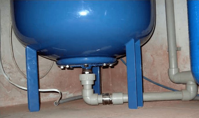
The accumulator device must be mounted in such a way that it can be easily disassembled in case of repair or maintenance, without draining all the water from the system.
The diameters of the connecting pipeline and the discharge pipe should, if possible, match each other, then this will avoid unwanted hydraulic losses in the system pipeline.
In the membranes of accumulators with a volume of more than 100 liters, there is a special valve for bleeding air released from the water. For small-capacity accumulators that do not have such a valve, a device for bleeding air must be provided in the water supply system, for example, a tee or a tap that shuts off the main line of the water supply system.
In the air valve of the accumulator, the pressure should be 1.5-2 atm.
The principle of operation of the accumulator
The hydraulic accumulator works like this. The pump supplies water under pressure to the accumulator membrane. When the pressure threshold is reached, the relay turns off the pump and the water stops flowing. After the pressure begins to drop during water intake, the pump automatically turns on again and supplies water to the accumulator membrane. The larger the volume of the hydraulic tank, the more effective the result of its work. The operation of the pressure switch can be adjusted.
During the operation of the accumulator, the air dissolved in water gradually accumulates in the membrane, which leads to a decrease in the efficiency of the device. Therefore, it is necessary to carry out preventive maintenance of the accumulator by bleeding the accumulated air. The frequency of preventive maintenance depends on the volume of the hydraulic tank and the frequency of its operation, which is approximately once every 1-3 months.

These devices are available in vertical and horizontal configurations.
The principle of operation of the devices does not differ, except that vertical accumulators with a volume of more than 50 liters in the upper part have a special valve for bleeding air, which gradually accumulates in the water supply system during operation. Air accumulates in the upper part of the device, therefore the location of the bleed valve is chosen exactly in the upper part.
In horizontal devices for bleeding air, a special tap or drain is mounted, which is installed behind the accumulator.
From devices of small sizes, regardless of whether they are vertical or horizontal, the air is bled off by completely draining the water.
When choosing the shape of a hydraulic tank, they proceed from the dimensions of the technical room where they will be installed. It all depends on the dimensions of the device: which one fits best into the space allotted for it, this will be installed, regardless of whether it is horizontal or vertical.
Hydraulic accumulator connection diagram
Depending on the assigned functions, the scheme for connecting the accumulator to the plumbing system may be different. The most popular hydraulic accumulator connection diagrams are shown below.

Such pumping stations are installed where there is a large water consumption. As a rule, one of the pumps at such stations operates constantly.
At the booster pumping station, the accumulator serves to reduce pressure surges during the activation of additional pumps and to compensate for small water intakes.
This scheme is also widely used when there is a frequent interruption in the supply of electricity to booster pumps in the water supply system, and the presence of water is vital. Then the supply of water in the accumulator saves the situation, playing the role of a backup source for this period.
The larger and more powerful the pumping station, and the more pressure it must maintain, the larger the volume of the hydraulic accumulator, which acts as a damper, should be.
The buffer capacity of the hydraulic tank also depends on the volume of the required water supply, and on the difference in pressure when the pump is turned on and off.

For long and uninterrupted operation, a submersible pump must make from 5 to 20 starts per hour, which is indicated in its technical specifications.
When the pressure in the plumbing system drops to the minimum value, the pressure switch automatically turns on, and when maximum value- turns off. Even the smallest water flow, especially in small water supply systems, can lower the pressure to a minimum, which will instantly give a command to turn on the pump, because water leakage is compensated by the pump instantly, and after a few seconds, when the water supply is replenished, the relay will turn off the pump. Thus, with minimal water consumption, the pump will run almost idle. This mode of operation adversely affects the operation of the pump and can quickly disable it. The situation can be corrected by a hydraulic accumulator, which always has the necessary supply of water and successfully compensates for its insignificant consumption, and also protects the pump from frequent switching on.
In addition, a hydraulic accumulator connected to the circuit smooths out a sharp increase in pressure in the system when the submersible pump is turned on.
The volume of the hydraulic tank is selected depending on the frequency of switching on and the power of the pump, the water flow per hour and the height of its installation.

For a storage water heater in the connection diagram, the accumulator plays the role of an expansion tank. When heated, the water expands, increasing the volume in the water supply system, and since it does not have the ability to compress, the most minimal increase in volume in enclosed space increases pressure and can lead to the destruction of the elements of the water heater. Here, too, a hydraulic tank will come to the rescue. Its volume will directly depend and increase from an increase in the volume of water in the water heater, an increase in the temperature of the heated water and an increase in the maximum allowable pressure in the water supply system.

The hydraulic accumulator is connected before booster pump along the water. It is needed to protect against a sharp decrease in pressure in the water supply network at the moment the pump is turned on.
The capacity of the accumulator for the pumping station will be the greater, the more water is used in the water supply system and the smaller the difference between the upper and lower pressure scales in the water supply before the pump.
How to install a hydraulic accumulator?
From the foregoing, it can be understood that the device of a hydraulic accumulator is absolutely different from an ordinary water tank. This device is constantly in operation, the membrane is constantly in dynamics. Therefore, the installation of a hydraulic accumulator is not so simple. The tank must be strengthened during installation securely, with a margin of safety, noise and vibration. Therefore, the tank is fixed to the floor through rubber gaskets, and to the pipeline through rubber flexible adapters. You need to know that at the inlet of the hydraulic system, the cross section of the liner should not narrow. And another one important detail: the first time you need to fill the tank very carefully and slowly, using a weak pressure of water, in case the rubber bulb sticks together from long inactivity, and with a sharp pressure of water it may be damaged. It is best to remove all air from the bulb before commissioning.
The installation of the accumulator must be carried out so that during operation it can be freely approached. It is better to entrust this task to experienced specialists, since very often the tank fails due to some unaccounted for, but important trifle, for example, due to a mismatch in pipe diameter, unregulated pressure, etc. It is impossible to conduct experiments here, because the normal operation of the plumbing system is at stake.

So you brought the purchased hydraulic tank into the house. What to do with him next? Immediately you need to know the level of pressure inside the tank. Usually, the manufacturer pumps it up to 1.5 atm, but there are cases when, due to a leak, the indicators decrease by the time of sale. To make sure that the indicator is correct, it is necessary to unscrew the decorative cap on an ordinary automobile spool and check the pressure.

How to check it? Usually a manometer is used for this. It can be electronic, mechanical automotive (with a metal case) and plastic, which comes with some pump models. It is important that the pressure gauge has greater accuracy, since even 0.5 atm changes the quality of the hydraulic tank, so it is better not to use plastic pressure gauges, as they give a very large error in performance. These are usually Chinese models in a weak plastic case. The performance of electronic pressure gauges is affected by battery charge and temperature, and besides, they are very expensive. So the best option is an ordinary automobile pressure gauge that has been tested. The scale should be on a small number of divisions, in order to be able to more accurately measure pressure. If the scale is designed for 20 atm, but you need to measure only 1-2 atm, then high precision not to be expected.

If there is less air in the tank, then there is a larger supply of water, but the difference in pressure between an empty and almost full tank will be very significant. It's all about preference. If it is necessary that the water supply constantly has a high pressure of water, then the pressure in the tank must be at least 1.5 atm. And for domestic needs, 1 atm may well be enough.
At a pressure of 1.5 atm, the hydraulic tank has a smaller supply of water, which will cause the pumping pump to turn on more often, and in the absence of light, the water supply in the tank may simply not be enough. In the second case, you will have to sacrifice pressure, because you can take a shower with a massage when the tank is full, and as it is empty, you can only take a bath.
When you decide what is more important for you, you can set the desired mode of operation, that is, either pump air into the tank or bleed the excess.
It is undesirable to reduce the pressure below the mark of 1 atm, as well as to exceed it excessively. A pear filled with water with insufficient pressure will touch the walls of the tank, and can quickly become unusable. And excess pressure will not allow a sufficient volume of water to be pumped in, since most of the tank will be occupied by air.
Setting the pressure switch
You also need to adjust the pressure switch. Opening the cover, you will see two nuts and two springs: a large one (P) and a small one (delta P). With their help, you can set the maximum and minimum pressure levels at which the pump turns on and off. A large spring is responsible for turning on the pump and pressure. By design, you can see that it kind of helps the water to close the contacts.

With the help of a small spring, the pressure difference is set, as specified in all instructions. But the instructions do not specify a starting point. It turns out that the reference point is the spring nut P, that is, the lower limit. The lower spring, which is responsible for the pressure difference, resists the water pressure and moves the movable plate away from the contacts.

When the correct air pressure is already set, you can connect the accumulator to the system. Having connected it, you need to carefully observe the pressure gauge. All hydraulic accumulators have the values of normal and limiting pressures, the excess of which is unacceptable. Manual disconnection of the pump from the network occurs when the normal pressure of the accumulator is reached, when the limit value of the pump head is reached. This happens when the pressure increase stops.
The pump power is usually not enough to pump the tank to the limit, but there is not even a special need for this, because when pumping, the life of both the pump and the pear is reduced. Most often, the pressure limit for turning off is set 1-2 atm higher than turning on.
For example, when the pressure gauge reads 3 atm, which is sufficient for the needs of the owner of the pumping station, you need to turn off the pump and slowly rotate the nut of the small spring (delta P) to decrease until the mechanism is triggered. After that, you need to open the tap and drain the water from the system. Watching the pressure gauge, it is necessary to note the value at which the relay turns on - this is the lower pressure limit when the pump turns on. This indicator should be slightly higher than the pressure indicator in an empty accumulator (by 0.1-0.3 atm). This will make it possible to serve the pear for a longer period of time.
When the nut of the large spring P is rotated, the lower limit is set. To do this, turn on the pump in the network and wait until the pressure reaches the desired level. After that, it is necessary to adjust the nut of the small delta P spring and complete the adjustment of the accumulator.

In the accumulator air chamber, the pressure must be 10% lower than the pressure when the pump was turned on.
An accurate indicator of air pressure can be measured only when the tank is disconnected from the water supply system, in the absence of water pressure. Air pressure must be constantly kept under control, if necessary, adjusted, which will add life to the membrane. Also, to continue the normal functioning of the membrane, a large pressure drop should not be allowed when the pump is turned on and off. Normal is a difference of 1.0-1.5 atm. Stronger pressure drops reduce the life of the membrane, greatly stretching it, moreover, such pressure drops do not allow comfortable use of water.
Hydraulic accumulators can be installed in places with low humidity, not subject to flooding, so that the flange of the device successfully serves for many years.
When choosing a brand of hydraulic accumulator, it is necessary to pay attention Special attention for the quality of the material from which the membrane is made, check the certificates and sanitary and hygienic conclusions, making sure that the tank is designed for systems with drinking water. You also need to make sure that you have spare flanges and diaphragms, which should be in the kit, so that in case of a problem you do not have to buy a new hydraulic tank.
The maximum pressure of the accumulator, for which it is designed, must not be less than the maximum pressure in the water supply system. Therefore, most devices can withstand a pressure of 10 atm.

To determine how much water can be used from the accumulator when the electricity is turned off, when the pump stops pumping water from the water supply system, you can use the diaphragm tank fill table. The water supply will depend on the setting of the pressure switch. The higher the pressure difference when turning the pump on and off, the greater the supply of water will be in the accumulator. But this difference is limited for the reasons stated above. Consider a table.

Here we see that in a 200 l membrane tank with pressure switch settings, when the pump on indicator is 1.5 bar, the pump off is 3.0 bar, the air pressure is 1.3 bar, the water supply will be only 69 l, which is equal to about a third of the total volume of the tank .
Calculation of the required volume of the accumulator
To calculate the accumulator, use the following formula:
Vt = K * A max * ((Pmax+1) * (Pmin +1)) / (Pmax- Pmin) * (Pair + 1),
- Amax - maximum consumption of liters of water per minute;
- K is a coefficient that depends on the power of the pump motor;
- Pmax - pressure when the pump is turned off, bar;
- Pmin is the pressure when the pump is turned on, bar;
- Pair - air pressure in the accumulator, bar.
As an example, we select the required minimum volume of a hydraulic accumulator for a plumbing system, taking, for example, the Aquarius BTsPE 0.5-40 U pump with the following parameters:
| Pmax (bar) | Pmin (bar) | Pair (bar) | A max (cubic meters/hour) | K (ratio) |
| 3.0 | 1.8 | 1.6 | 2.1 | 0.25 |
Using the formula, we calculate the minimum volume of HA, which is 31.41 liters.
Therefore, we choose the next closest GA size, which is 35 liters.
The volume of the tank in the range of 25-50 liters is in perfect agreement with all methods for calculating the volume of HA for domestic plumbing systems, as well as with empirical assignments from different manufacturers of pumping equipment.
With frequent power outages, it is advisable to choose a larger tank, but at the same time, it should be remembered that water can only fill the tank by 1/3 of the total volume. The more powerful the pump is installed in the system, the larger the volume of the accumulator should be. This sizing will reduce the number of short pump starts and extend the life of the pump motor.
If you bought a large-capacity hydraulic accumulator, you need to know that if water is not used regularly, it stagnates in the HA tank and its quality deteriorates. Therefore, when choosing a hydraulic tank in a store, you need to take into account the maximum amount of water used in the water supply system at home. Indeed, with a small water consumption, it is much more expedient to use a tank with a volume of 25-50 liters than 100-200 liters, the water in which will be wasted.
Repair and prevention of the hydraulic accumulator
Even the simplest hydraulic tanks require attention and care, like any device that works and benefits.
The reasons for repairing a hydraulic accumulator are different. This is corrosion, dents in the body, violation of the integrity of the membrane or violation of the tightness of the tank. There are also many other reasons that oblige the owner to repair the hydraulic tank. In order to prevent serious damage, it is necessary to regularly inspect the surface of the accumulator, monitor its operation in order to prevent possible problems. It is not enough to inspect the GA twice a year, as stipulated in the instructions. After all, one malfunction can be eliminated today, and tomorrow not to pay attention to another problem that has arisen, which over the course of six months will turn into an irreparable one and can lead to the failure of the hydraulic tank. Therefore, the accumulator must be inspected at every opportunity, so as not to miss the slightest malfunction, and to carry out their repair in time.
Causes of breakdowns and their elimination

The reason for the failure of the expansion tank may be too frequent switching on / off of the pump, water outlet through the valve, low water pressure, low air pressure (below the calculated one), low water pressure after the pump.
How to troubleshoot a hydraulic accumulator with your own hands? The reason for repairing the accumulator may be low air pressure or its absence in the membrane tank, damage to the membrane, damage to the housing, a large difference in pressure when the pump is turned on and off, or an incorrectly selected volume of the hydraulic tank.
Troubleshooting can be done as follows:
- to increase the air pressure, it is necessary to force it through the tank nipple with a garage pump or compressor;
- a damaged membrane can be repaired at a service center;
- the damaged case and its tightness are also eliminated in the service center;
- you can correct the difference in pressure by setting too large a differential in accordance with the frequency of switching on the pump;
- The sufficiency of the tank volume must be determined before it is installed in the system.
Most of the work related to the development and installation of water supply systems requires a certain amount of experience and a clear understanding of the specifics of the operation of a water supply system based on an artesian well. But even in such difficult task there are many individual elements and assemblies that are quite capable of being installed with your own hands. For example, connect a hydraulic accumulator and a pressure switch to a pump. The complexity of such work is minimal, the installation of a hydraulic accumulator for water supply systems does not require special skills or knowledge of electrical installation;
What and how to adjust in a system with a pump and a hydraulic accumulator
There are three classic options for the layout of pumping and accumulator equipment for a well:
- In the first case, a submersible pump is used, located in a well under a layer of water of 1-2 meters, automation, a filter and a hydraulic accumulator can be located in a caisson at the head of the well, but with the same success for all equipment, installation can be performed in the basement of the house;
- In the second case, a surface pumping system and a hydraulic accumulator are used, which do not have the pressure capabilities of submersible units, so they are tried to be located as close as possible to the well and the water level. Most often, a pump with a water pressure switch and the accumulator itself are mounted in the caisson;
- In the third variant, also called dacha-garden, water from the well is raised by a surface pumping unit or a simple vibrating “Kid” into a huge water tank. Water can be supplied to the water supply at home without using an additional pumping device, only the natural pressure of the water column, water the beds and fill Summer shower, wash appliances, in general, use the installation on your own.
For your information! In any case, before setting up the accumulator pressure switch, you will need to correctly calculate the required water pressure in the house, taking into account the requirements household appliances and the existing height difference between the level of the pump and the maximum point of water extraction in the house, most often this is an air outlet valve for the heating system.
The sequence of work when installing a hydraulic accumulator with your own hands
Immediately after drilling the well and determining the debit, they begin to equip it. Based on the depth of the aquifer and the degree of its contamination with salts and sand, a decision is made on the method of designing the head, where it is necessary to put the pump, and which version of the pumping system and pumped storage installation fit better Total.
Installing a hydraulic accumulator paired with a submersible pump
A submersible pump unit has always had a lot of advantages, but the more powerful and perfect the pump, the larger the volume of the pumped storage unit must be used to compensate for pulsation and water hammer. Therefore, when choosing a scheme for installing pumping equipment and a hydraulic accumulator device, the system parameters were successively determined:
- The required pressure and water flow to ensure normal water supply to the house, taking into account the depth of the well and the distance from its head to the building of the house;
- What pump power and the volume of the accumulator tank will provide the necessary performance and smooth operation of water supply systems;
- Where to locate the main components of the equipment of the water supply system: pump, accumulator, automation and filters.
For your information! To ensure the operation of expensive and powerful pumping systems of Danish, German and Italian manufacturers, hydraulic accumulators from 50 to 100 liters are most often used, which are installed in a well-equipped basement or basement.

The high pressure and pressure of "European" models make it possible to install pumped storage units at a considerable distance from the well, even if the building has a second floor and household appliances that require increased water pressure in the water supply system.
The standard piping connections are shown in the diagram.
This option of installing a hydraulic accumulator in a water supply system provides a number of significant advantages:
- A well-ventilated and partially heated room helps prevent condensation on the surface of the accumulator and electric automation systems;
- It is convenient to maintain the accumulator tank and filter, according to existing standards, it is recommended to check the pressure gauge readings in the air chamber of the accumulator cylinder and the settings of the pressure switch for the accumulator at least once every two to three months;
- If necessary, you can drain the water from the water supply system directly into a reserve tank or into a sewer.
Important! Installation of a hydroaccumulating device in a separate room requires that polypropylene pipes be laid in the ground to a depth not less than the freezing depth with a slope towards the well of at least 2o. This will allow air bubbles to escape to the filter and the connection point of the hydrostorage tank.
The basis for the construction of such a node of the water supply system is a hydraulic accumulator tank, most often of a vertical design on supports. At the bottom of the tank, a five-pin fitting is screwed in, through which the pump line, outlet line, pressure switch sensor and pressure gauge are connected. The pump line is most often made from a polypropylene pipe from a well to a hydraulic accumulator. In small water systems, connections may be made with flexible hoses, and the relay and filter are usually located on the special fastening at least one meter above the floor.
The disadvantages of such schemes include the sensitivity of submersible pumping systems to a high content of sand and salts. The non-return valve in submersible systems is most often located at the outlet of the pump at great depths. After raising a certain amount of water, the sand remaining in the outlet pipe slowly settles, sinking to a depth, and gradually accumulates on the body of the check valve, gets inside the device, which leads to the failure of an expensive unit.

For domestic submersible pumps of the "Vodomet" type, you can install in a caisson or head well. Most often, such a scheme is used for low-power pumping systems, with a shallow aquifer.
In the photo you can see the classic correct option installation of a submersible pumping system and a hydraulic accumulator in the well.
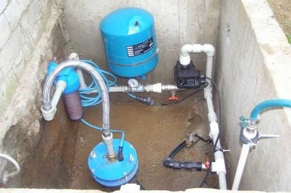
The output from the wellhead is fed to the filter, then to the accumulator, and only after that to the pressure switch of the submersible pump. The outlet from the well to the filter and accumulator is made with a flexible hose, all other fittings are soldered from plastic pipes. What gives such a scheme? Such an installation allows you to issue sand-free water to the accumulator and relay.
By connecting the system to the water line through a filter, the reliability of the automation is significantly increased. The relay should be freed from dirt and sand as much as possible, otherwise, after a couple of months there will be interruptions in operation.
In the central part of the output line running from the pressure switch to the entrance to the house's plumbing system, there is ball valve with a tee, which allows you to solve a rather difficult question: how to drain the water when adjusting the pressure of the automatic relay.
For large height differences, or if the water in the well is of very poor quality, install additional pumped storage devices with volume separation clean water and technical water. The system consists of two hydraulic accumulators and a clean water tank. In a set for the pump in the well, a standard hydraulic accumulator-accumulator of raw water is installed, from which the liquid through the filter of dirt and neutralization of suspensions enters the inlet of the vortex pump, which pumps water through membrane filters into the accumulator for clean water, located in the house or basement. Water is taken from the tank and sent to the place of use in the water supply system by a conventional network pump.
A pumping device that takes untreated water from a well should be as insensitive as possible to the content of hard salts and clay suspension in artesian water.
Easy installation of accumulator with surface pump
It is best to install a properly tuned centrifugal pump with an ejector and a small hydraulic accumulator for these purposes. The first accumulator will not be used as a backup source of water, so you can limit yourself to a small membrane model of 10-12 liters.
Special differences in the use and installation of a hydraulic accumulator with surface pump no, except that:
- The installation of the accumulator and pressure switch should be carried out as close as possible to the pump;
- There must be a filter and a check valve between the centrifugal pump and the accumulator, otherwise, every time you turn on the tap with noise and vibration, you will receive a mixture of air and water.
Country-garden option for installing a hydraulic accumulator
The country-garden option, for all its primitiveness, makes it possible to very rationally use the capabilities of pumps with high water flow and get by with the minimum size of the accumulator.
The advantages of the pump installation option shown in the photo are obvious. Firstly, there is no need to install a large and expensive accumulator, which does not always make sense to purchase for the needs of a summer residence. Secondly, the relay on the pump can be connected with a flexible hose to the place where water is taken from the tank and adjusted to the minimum 0.1 and 0.2 atm off and on, respectively. In some cases, the pressure switch membrane is replaced with an electromechanical timer that allows you to pump out a certain amount of water from a well or well at a programmed time interval.
Conclusion
All of the listed options for installing a hydraulic accumulator have been tested in practice and proven to be reliable. If the quality of water in your estate or private house leaves much to be desired, use the pump method described in the article with two accumulators and a membrane water purification filter. Most branded hydraulic accumulators have a certified rubber sheath in which you can store a supply of purified water for a long time. drinking water. For technical needs, you can use a conventional tank, described in the last subsection, complete with a small and cheap vortex pump.