What is a mnemonic diagram of a dispatch control board. Telemechanics in the power supply of industrial enterprises - mnemonic diagrams and electrical equipment of control panels and consoles
LLC "TREI GmbH", Penza
The article discusses automated system dispatch control the processes of distribution of electricity in the electrical network at JSC "UK TMK" using mnemonic diagrams. The structure of the system and the main technical solutions are presented in detail.
Energy is one of the strategically important branches of our industry, the basis of the country's economic independence and security. Today, the energy sector is on the cusp of transformation. In this regard, the efficient management of energy capacity and energy distribution is of great importance. Improving the efficiency of generating capacities, as well as establishing optimal distribution modes are of great importance and allow reducing energy costs, as well as maximizing product sales. In such a situation, one of the priority directions for improving the control modes of energy facilities is the construction of modern automated production process control systems (APCS). At many enterprises, systems are being introduced that make it possible to efficiently manage energy capacities.
Currently being developed in Kazakhstan (Ust-Kamenogorsk), the automated system for dispatching power supply of JSC "UK TMK" using a mnemonic diagram (abbreviated name ASDUE) is a similar system effective management.
The developed power supply dispatch control system is being created in order to increase the efficiency of managing the processes of power distribution in the electrical network, reduce the time to restore power supply to the plant's consumers after emergency outages, increase the labor productivity of operating personnel in scheduled work and provide:
Reflection of the actual position of the oil and vacuum switches of the power supply system of the plant on the mnemonic diagram and the dispatcher's workstation;
Virtual control of the symbols of disconnectors, load-break switches, separators, short-circuits on the mimic diagram and the dispatcher's workstation with time fixation and the basis of their commutation;
Management of grounding symbols for lines and electrical equipment on the mnemonic diagram and the dispatcher's workstation with time recording and the basis of their commutation;
Control of the consumed current at the input cells and outgoing lines at the dispatcher's workstation;
Remote control of oil and vacuum switches at the facilities of the plant from the dispatcher's workstation;
Warning and emergency alarms from objects: generalized, ATS, automatic reclosing, display of electrical protections;
Displaying information about emergency shutdown of the circuit breaker on the dispatcher's workstation;
Safety for a month of all events on the mnemonic diagram and the time of fixation with the possibility of printing;
Record and preservation for a month of operational telephone conversations of the dispatcher on each line with time fixation and with the possibility of printing;
Visualization of the plant's electrical network and the main monitored parameters on a mnemonic diagram for collective use.
Rice. 1. Three-level system of ASDUE
System structure
The plant's electrical network is a geographically distributed structure consisting of stations and substations with electrical equipment installed in the premises, as well as on open switchgears. The basis for the construction of ASDUE is the principle of constructing a logical part based on programmable logic, that is, a programmable controller TREI-5B-02 is used to implement the control, measurement and control algorithm. The programmed logic of the algorithm is implemented by interrogating the actual state of the input signals, comparing the values of these parameters with those specified in the program, and when the dispatcher confirms the actions being performed by issuing control output signals.
According to its architecture, ASDUE is a three-level distributed computing system, divided by functions (Fig. 1).
The first level of the hierarchy is the means of instrumentation installed directly at the local facilities of the plant's electrical network, which are part of the structure of this project.
The second level of the hierarchy is made up of controllers. This layer is characterized by the geographical and functional distribution of hardware.
The third level is the level of the ODS (operational dispatch service, automated workstations of the dispatcher, operational and managerial personnel). It is built on the basis of client-server technologies.

Rice. 2. Complex of technical means
System composition
In accordance with the purpose of the ASDUE, it contains:
Information and control system of the electric network of the plant;
Mnemonic diagram for collective use of the plant dispatcher for power supply.
The main tasks that are set for the ASDUE system are control of the actual position of the VM oil and vacuum switches (426 points), control of the actuation of protection devices, control of the consumed current, control of the symbols of electrical devices on the mnemonic diagram. Ensuring the required reliability of the system functioning (redundancy of master modules, the possibility of transition from remote control to local). Possibility of replacing controller modules without stopping the system. Hardware and software diagnostics of the controller and input signals. Build-up functionality systems at the lowest cost due to the use of a single series of controllers. Display of actual operational and archived information on a general mnemonic diagram, mnemonic diagrams of local objects, real-time and history trends, printed reports. The proposed technical solutions ensure the integration of ASDUE as an integral part of the overall network of the plant.
ASDUE is a set of control cabinets and auxiliary equipment, namely:
Cabinets with microprocessor controllers are intended for collecting and processing information from the structural elements of the plant's electrical network and remote control of electrical switching devices (VM) from an automated workstation (AWP) of the dispatcher;
Cabinets with devices for communication with objects (USO) are the physical and logical continuation of cabinets of microprocessor controllers with the implementation of similar control, measurement and control functions;
Cabinets with power relays and current converters are intended for connection to high-voltage cells in order to ensure control of the oil circuit breakers of the cells from microprocessor controllers and USO, as well as issuing signals of measured currents to the controllers;
The cabinet of the local LAN server is designed to collect information from system microprocessor controllers and then provide information about the status, execution of control actions and malfunctions technological equipment the electric network of the plant on the mnemonic diagram and the workstation of the dispatcher. The local server is connected to the general computer network of the plant to view technological information on remote computers and store an archive database with a depth of 1 year on the general server of the plant.
The local server cabinet includes the following systems:
Automatic digital recording of audio information "SPRUT-7A-7", which allows recording audio information from analog-digital communication channels and registration of incoming (caller ID function) and outgoing numbers, date, time and duration of the communication session;
The PLI 8-16 video information display system controller generates a split-screen image for it and controls the operation of the entire display system equipment complex.
The video information display system based on four SYNELEC C50X-BB-SL video cubes with a diagonal of 50 '' is designed to visualize (display) the actual configuration of the plant's electrical network, operational information in real time, namely:
Current consumption by the main consumers of the plant;
The state of the switching devices of the electrical network;
Displaying the process of performing operational switching by operating personnel (dispatcher, duty officer);
Display of emergency situations occurring in the electrical network;
Control of withdrawal for repair, and preparation of equipment for repair;
Monitoring of stationary and portable groundings.
Software top level implemented: iFIX Plus SCADA Pack Server Version 3.0 (the number of points is not limited), iFIX Standard HMI Pack Runtime Version 3.0 (the number of points is not limited), iFIX iClient Runtime Version 3.0, Nautsilus OPC server (USB). The video cube controller has Windows 2000, SP3 software, Windows SERVER 2000, Windows XP Pro, Sp2 workstations.
Main technical solutions
Enlarged diagram of a complex of technical means
As already mentioned, ASDUE is a three-tier distributed system. The second level of ASDUE provides the following functions: automated control of the actuating mechanisms of the VM oil switches; primary processing and normalization of signals from measuring current transformers, it is built on the basis of the Trei-5B-02 controllers from the company "TREY GMBH", Penza, License No. 19-02. The upper level implements the functions of the human-machine interface and is built on the basis of General Electric software products. In fig. 2 shows an enlarged diagram of the complex of technical means of ASDUE. As you can see from the diagram, the Control System has a distributed structure and consists of:
Mnemonic diagrams for collective use of the dispatcher of the plant for power supply;
Local server;
Dispatcher and engineering stations (AWPs 1 and 2);
System controllers ШК1-ШКn .., included in their composition of remote USO and cabinets with power relays and current converters. Communication between the controllers is carried out via Ethernet 100 mb / s, which provides a high exchange rate for obtaining the necessary information.
The main controller and SCADA iFIX Plus Pack Server communicate over a 100 Mb Ethernet technological network. Stable operation of the mnemonic diagram for collective use, the local server and operator stations is provided by uninterruptible power supplies installed in the operator's room.
The main controller ШК0 is responsible for communication with the local server and monitoring the state of the equipment of the electric network of the plant through the polled system controllers ШК and the remote USOs that are part of them. The main controller transmits the received data for display on SCADA, and through it supervisory control of the system controllers is carried out (changing settings, operating modes, priorities). To increase the reliability of the ASDUE operation, and to prevent the loss of communication between the local network objects and the main controller, redundancy of the processor part and power supplies is used on it. This configuration will increase the survivability of the system. The block diagram shown in Fig. 2, gives an idea of the distribution of technical means at the facilities of the electric network of the plant. In this case, the use of the RS-485 (STBUS) and Ethernet protocol makes it possible to expand the system and save on cable products when connecting remote objects. The server performs the functions of collecting, storing, archiving and issuing operational data. The operator's station provides for remote (supervisory) control of VM switching devices. The choice of SCADA iFIX facilitates the integration of the automated process control system under construction with the existing automation tools. If necessary, it is possible to transfer technological data to the common server of the plant. Storage of technological settings is carried out in non-volatile memory controller, which allows the system to remain operational in the event of a failure or lack of communication with the local server.
This configuration of the system allows: to reduce the recovery time of the system due to modularity (mezzanine modules) and quick replaceability of its elements. Replacement of a separate failed module or control measuring device can be carried out without interrupting the operation of the system; ensure good reliability indicators due to redundancy and duplication of the most significant system components. In particular, if one of the master modules fails or if the connection with one of them is lost, the transition to the backup will be made.
Short description
technical components
Microprocessor-based
controller
The TREI-5B-02 device is intended for local and distributed systems of automatic monitoring and control of technological processes in industrial enterprises with normal and explosive production.
The product has a certificate of approval of the type of measuring instruments No. 2641 (Kazakhstan No. 1503), TUV certificate, permission to issue and use No. 507-EV-1YA1, the manufacturer has a certificate of conformity to the quality management system ISO 9001 No. ROSS RU. IS50.K00019. The serial interface based on RS-485 and a wide range of I / O modules allow you to create distributed, multi-level and multifunctional systems. Unified communication protocol ST-BUS simplifies programming and collection of information from I / O channels. All input and output data structures are unified. The processor part of the controller is a PC compatible computer with the necessary set external devices. QNX real-time operating system and IsaGraf development environment. The design of the TREI-5B-02 controller is based on the "3 U Euromechanics" format. The housing is available in open or closed design, if necessary, with DIN-rail mounting. Modules with size printed circuit boards 100x160 mm have light indication on the front panel and a 48-pin connector at the back for connecting power, serial interface and I / O channels. The basic interface of the controller is a serial ST-BUS interface based on RS485, which allows creating distributed systems with a length of a physical line without repeaters up to 1200 m. The maximum interface speed is up to 1.25 Mbod. I / O modules have their own Pic-processor and can work autonomously. The collection of information via the ST-BUS communication protocol from the input / output modules is carried out by the M701E master module or an industrial computer with a serial RS485 interface. The range of I / O modules allows you to create multi-channel and multifunctional systems. The universal module, completed with TREI-5 series mezzanine modules, has a full set of connected devices. Multichannel modules of the same type for discrete and analog input / output, pulse input provide up to 4000 channels per master module.
The master module performs the basic computational functions of the controller.
In its composition, it contains:
Master module base board;
Processor module with Pentium processor;
10/100 Ethernet communication adapter card;
Galvanically isolated RS485 ports;
ST BUS controller;
Non-volatile static RAM;
Flash disk;
Infrared port;
Watchdog timer.
The chassis contains the following I / O modules (all industrial I / O modules):
The ION M732U module is a universal 8-channel I / O module.
The specific channel type is set by the installed mezzanine. The mezzanine is a module-mounted primary signal conversion unit. The mezzanines of the IDIG-24VDC type are used, which are used to connect discrete 24VDC signals, and the IANS 0-20 mA mezzanines are used to connect the input analog signals of 0-20 mA;
M754D modules - 32 discrete input channels 24VDC;
Modules M754O - 32 discrete output channels 24VDC;
M743D modules - 16 discrete input channels 24VDC;
M743O modules - 16 digital output 24VDC channels.
All channels are isolated. In addition to the I / O modules and the master module, a P701 A power supply module with a power of 40 W is installed in the chassis and provides power to the controller elements. For mezzanines of analog input, the main reduced error does not exceed 0.025%. For mezzanines of the analog output, the main reduced error does not exceed 0.1%. Conversion is carried out by a 16-bit DAC. Detailed description modules are presented on the website of TREI-GmbH.

Video information display system
The proposed solution uses projectors built on DLP ™ technology from Texas Instruments. DLP ™ technology is the de facto standard for video walls due to the elimination of the pixel burn-in effect inherent in plasma displays. The DLP projector's declared MTBF is at least 100,000 hours (more than 10 years of continuous operation). The proposed solution is based on XGA (1024x768) Clarity-Synelec video cubes. Video cubes have a built-in processor that allows processing digital information streams at a speed of up to 16,000 Mb / s, which is tens of times faster than similar systems. Unlike built-in splitters - simple input signal splitters, Clarity-Synelec video cubes are a full-fledged multichannel digital processor. Two DVI inputs allow simultaneous and independent display of two scalable and movable information windows. The presence of two independent inputs at the video cube ensures high reliability of the equipment: if one video processing channel fails, the second channel remains operational. To receive the highest quality images in Synelec video cubes use super-black anti-glare transmissive screens. Today they are the most high-quality and high-tech translucent screens on the world market. These screens are offered by Clarity-Synelec with the highest demands on image quality (graphic resolution, clarity, contrast). They are characterized by a wide field of view and the absence of glare even under strong illumination by extraneous light sources (the super-black screen absorbs 99.5% of the light from external sources). By their properties, the screens provide a practical absence of inter-screen gaps, and, consequently, the most comfortable conditions observation. Microscopic optical elements ensure high brightness uniformity across the entire screen surface, Wide angle view: 180 degrees - horizontally, 180 degrees - vertically. Providing the best clarity and contrast when displaying a signal with a high graphic resolution allows for effective cleaning of contaminants (most lenticular-raster optical transmission screens have a microlens outer surface and can only clean contaminants with compressed air. Screens have a smooth protective outer surface that allows effective cleaning) ... The video wall controller, PLI 8-16 Network Controller, is a powerful control system for real-time display of rich computer graphics and video images. It combines a modern hardware platform and software guaranteeing high performance, reliability and ease of use.
The video wall can combine up to 80 video cubes. The PLI 8-16 controller generates a split-screen image for it and controls the operation of the entire display system equipment. Due to the peculiarities of the controller architecture, the digitization and display of video sources occurs in real time without loading the central processor and without loss of information.
The controller uses the most Hi-tech and protocols. The digital protocol DVI is selected as the interface for transmitting the displayed information. This solution made it possible to get rid of noise, interference, frequency and phase signal distortions typical for analog data transmission channels. Due to the absence of analogue channels of information transmission in the system, the image is of excellent quality and stability.

The PLI 8-16 controller allows you to launch any application from the network by displaying it in a window or on the entire split-screen, that is, as required by the display scenario. Networked UNIX applications can also be launched and displayed on a split screen in a similar manner. The number of windows with applications is practically unlimited. Each window can be scaled, moved around the display wall, or enlarged to fit the entire screen. The controller is easy to operate and does not require any special skills from the operator familiar with the operation of Windows. Distinctive features of the PLI 8-16 controller are:
Upgraded hardware platform that allows you to build split screens up to 80 video cubes using a single PLI controller. When using more complex configurations, the size of the video wall is not limited;
High-performance graphics processors with digital outputs that provide signal display without noise, distortion or interference;
Ability to work under Windows and Linux operating systems. Cross-platform software allows using the controller both in Windows and Unix networks, and in mixed networks;
Versatility and multitasking. The controller can simultaneously execute user applications, digitize video signals, import information from a local area network and display the results of work on the video wall in the form of freely movable and scalable windows;
Flexibility and scalability. The controller can be easily reconfigured to solve a variety of tasks and can be expanded if necessary to expand the functionality of the system or the size of the split-screen. The industrial design of the controller allows it to be installed in a standard 19 '' rack cabinet, which provides increased noise immunity and improved ventilation of computer components.
The Clarity-Synelec PLI 8-16 Network Controller allows:
Summarize the resolutions of individual video cubes, providing an extremely high graphic resolution of a split-screen (for example, for a video wall in a 2x2 video-cubes configuration, the resolution of a split-screen is 1536x2048 pixels);
Work under Windows and Linux operating systems;
To execute local programs(for example, SCADA applications used by the customer);
Work with network databases;
Display copies of network applications windows or copies of monitors of networked workstations on the video wall;
Work with any image as with a regular Windows window: move, scale, minimize or maximize up to the size of the entire split-screen;
Manage display scripts (including from remote workstations);
Form, save and recall the scenarios required for display in a given period of time (for example, in different operational situations, normal / emergency);
Automatically monitor equipment with displaying the status of devices (including at remote workstations);
Generate messages about errors, failures and malfunctions, perform predetermined actions corresponding to each described problem (change the script, turn off and on the lamps, etc.);
Track specified messages on a computer network and in serial ports, perform predetermined actions corresponding to each described message (part of the desired message can be used as a variable for the action being performed);
Perform the specified actions according to the schedule (for each action you can set: time of day, days of the week, dates);
Save a snapshot of the image on the entire split screen as a file.

Rice. Interaction of logical subsystems at the time of drawing generation
Brief description of software components
As mentioned above, the TREI-5B-02 controller is a PC compatible programmable logic controller. This controller runs the QNX operating system. The architecture of this operating system is specially designed for use in real-time systems, which makes it the most optimal for use as an operating system for controllers. The operating system image and the files necessary for the controller are located on a flash disk or disk-on-chip. An ISaGRAF target task has been launched on the controller, which polls I / O modules and executes algorithms. The target uses a configuration file containing a description of the algorithms and a description of the controller's hardware configuration. The configuration file is prepared using the ISaGRAF software package. ISaGRAF is an instrumental CASE system for technological programming of controllers. Developed by CJ International. ISaGRAF is full support for all languages of the IEC 1131 3 standard. The development environment provides a complete set of tools for interactive program creation, their effective debugging, documentation and archiving of projects.
The upper level of the APCS is built on the basis of the SCADA package iFIX from General Electric. This software package includes tools for processing, accumulating and displaying information, as well as configuration tools that allow you to customize the system components in accordance with the requirements of a particular object. The connection between the controller and the SCADA-system is provided with the help of the Nautsilus OPC server, twisted pair is used as a medium, Ethernet is the transport protocol.
Specialized software
A specialized software package Com.Base is supplied for the PLI 8-16 controller, which is an integrated multi-user control system for video wall equipment and information display process. Com.Base was developed by Synelec Telecom Multimedia as a universal software package that provides a single convenient and understandable user interface for automated control of all the variety of equipment and processes inherent in professional display systems. The controller architecture and software ensure seamless integration into the existing computer network. The use of TCP / IP as the main communication protocol for all devices and modules of the system allows for remote diagnostics and system administration, including via the Internet. For remote control network or host computers and sharing network resources, additional software can be installed. Synelec's full-featured Com.Base software provides the dispatcher with a comprehensive set of video wall controls. Due to its simplicity and friendly user interface, Com.Base provides effective control over the system at three main stages of the system operation: a) system configuration, b) system operation, c) system maintenance.
Let's consider the interaction of the main subsystems in the process of automatic creation of a mnemonic diagram in the iFix environment, which is in the configuration mode: a start is made with the task of building a picture, and the "SOLOMON" block starts its work. Its purpose is one of the primary: preparation, control and maintenance of the base of the object model of the invisible wireframe of the future schema. The necessary data streams are requested through the "HERMES" communication intermediary, which, in turn, contacts the storage of external information through the "DARIUS" subsystem that supports the multiplicity and diversity of sources and converts data to a single internal standard. Now, to master a new type of storage, it is enough to just inherit the template from the specialized class and fill it with the implementation of access and processing. If necessary, information channels are encrypted, decrypted by the "ARES" block. Important role the abstract entity "ProClass" plays here, which is the main building material logic of object constructions. Its structure is not hardcoded into the code, but is dynamically formed using the abstract factory pattern and initialization files, implementing concrete descendants. Thus, it becomes possible to make changes to classes in non-fields of the program code. The emphasis is on two components - the logic is highlighted (the semantic content of the object) and the set of scripts associated with it is delegated. Objects are created and initialized. Links and groupings are added to objects according to the created scheme. An optionally developed mechanism for automatic generation of tag names is based on the logical position of the object and its environment. As a result, a collection of all task objects is prepared in a single repository.
In fact, the "LEONARDO" unit works out three modes:
1_Preparation for the use of minimally indivisible graphic objects from the point of view of the system with the end result - a library of primitives ("Atoms"). The need for this stage is primarily due to the idea of weakening the close relationship with the SCADA environment used.
2_Based on the resulting library of graphic "atoms", more complex entities of the "Symbol" class are constructed - logically complete images appearance instances of projects. If necessary, their animation is activated. Each type of symbol is presented in the singular.
3_Using the temporary storage of symbol instances and the object field prepared by the "SOLOMON" block, the final creation of the mnemonic diagram elements and their placement in the figure is performed. The transfer of information between the blocks and here goes through a single center. Upon completion, the newly created drawing is saved and placed in the logical storage of visual forms, so that it can later be used by the MEMPHIS user interface subsystem.
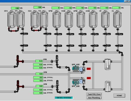
Appointment ... Mnemonic diagram (screen form) is a visual graphic representation of the technological process, integrated with monitoring and control facilities. It is the most important source of information about the nature and structure of connections, the current state of variables (including those related to the violation of technological modes, accidents, etc.) and allows the operator-technologist:
· Facilitate memorization of the course of the technological process and the purpose of devices and controls;
· To determine the methods of action in different modes of operation of the object;
· Help to simplify the search and identification of the necessary information for the prompt adoption of the right decisions.
Graphics components ... All SCADA systems include tools that allow you to create both static elements of mnemonic diagrams (contour images of technological devices, pipelines, etc.), and to animate (animate) these elements (create dynamic objects). These funds include:
· Sets of graphic drawing primitives (line, rectangle, ellipse, curves, text) and tools for their layout to create unique custom objects);
· Ready-made libraries of typical graphic objects: technological objects (devices, mechanisms, machines, etc.), displays, pointers, sliders, buttons, switches used to display variables and control the process. These libraries can be extended by the user. When constructing a mnemonic diagram, drawing is first carried out
static image of the working window. Usually these are devices technological process or their technological sequence, pipelines, background, explanatory text, etc.
The next step is to add dynamics to the mnemonic diagram, i.e. animation of the drawn (or selected from libraries) elements. Animation is understood as the ability of elements to change their properties when changing the variables of the technological process. Modifiable properties are thickness, line color and style, fill color and style (if it is a filled shape), and size, position, and orientation of elements. It also provides for direct input of variables (numbers and text, sliders) and process control using buttons and switches (Start / Stop, On / Off, Window Call, etc.).
Construction principles ... With a wide variety of technological processes, designing a good mnemonic scheme is in many ways an art, but we can recommend the general principles of construction:
– brevity and clarity- the mnemonic diagram should be simple (the contours and proportions of the devices are close to the type of real prototypes), should not contain minor elements, and the displayed information should be clear and specific, convenient for perception and further processing. The mnemonic scheme should provide a minimum, but adequate for control and management, number of variables, should not be "overloaded" with information for clarification (secondary trends), which is more convenient to nest in the form of pop-up windows called at the request of the operator;
– maximum linearity process images, i.e. it is advisable to highlight the main line of the process, obeying the rule of visuality: reading "from left to right" and "top to bottom", minimal use of parallel contours, which will greatly simplify perception
- autonomy- isolation from each other of the sections of the mnemonic diagram corresponding to the autonomously controlled and controlled objects and units. These separate areas should be clearly separated from others and have a complete, easy to remember and different structure.
– unification- symbols of similar objects and processes should, if possible, be combined and unified;
- visual accent to control and management elements- First of all, the elements that are essential for assessing the state, making a decision and influencing the controlled object should be highlighted (by size, shape or color) (i.e. help to quickly navigate, identify and eliminate deviations and malfunctions);
– taking into account the human factor- the mnemonic diagram should be developed and improved taking into account the opinion of the operating personnel.
To evaluate mnemonic diagrams, the following are used:
- coefficient of information content - the ratio of the number of passive (static) elements and active (dynamic);
- field filling factor - the ratio of the number of passive mnemonic elements to the total number of mnemonic elements.
When designing mnemonic diagrams, they usually offer several options. The final one is chosen by experiment (they simulate the operator's activity on a computer with various mnemonic schemes). The evaluation criteria are the time of solving problems and the number of mistakes made.

In fig. 2 shows the main zones of the mnemonic diagram. With the horizontal dominant of the presentation of information, the following zones are distinguished: basic information area- reflects the general structure of the technological process. It contains the main apparatus, pipelines, as well as the information load accompanying the technological process.
additional information area- buttons for trend graphs, reports, "start / stop", etc. can be located here.
switching zone- due to the impossibility of rational display of all information in one window ("the curse of the format").
With the help of the area means, it is possible to call additional windows on which alarms, trends (per day, month, year), and individual process sections are detailed in more detail. This approach unloads the mnemonic scheme, makes it possible to obtain the necessary information about the object, which deserves attention at the moment. A clear difference with the vertical dominant of the zones - area 2 (additional information) is located to the right of area 1 (basic information). This is primarily due to the size of the described objects (the displayed process is small in volume), which allows you to allocate more space for explanatory information. This arrangement of areas can be used for pop-up windows, i.e., a detailed examination of individual sections of the technological process.
For the convenience of visual perception of the functional diagrams of objects controlled or controlled, mnemonic diagrams are used - graphic images of the diagrams of these objects. A mnemonic diagram can display, for example, a CNC machine shop, a technological process or a system, for example, an energy network. In other words, a mnemonic diagram is an informational conditional model of a system or process in the form of symbols that designate parts of the system, as well as their connections.
The mnemonic diagram graphically reflects the structure of the entire system, thereby facilitating the work of the operator, who, thanks to such a scheme, himself more easily remembers the structure of the system, the relationship of parameters, the purpose of certain controls, instruments, machine tools, etc.
For the operator controlling the processes, the mnemonic diagram serves, perhaps, one of the most important sources of information about the processes currently taking place in the system, about the structure and nature of these processes, about the current status of the system, in particular, about accidents and violations of normal operation modes.
If the controlled object has a complex structure, has many parameters that must be operatively controlled, and is technologically complex scheme... If during the operation of the object the technological scheme itself can change, in these cases mnemonic schemes turn out to be very, very effective tools. They can display the states of individual devices, machines, units, the values of various parameters, and also provide general information about the course of the technological process.
An operator working in conditions of an abundance of information coming to him, thanks to mnemonic diagrams, can more efficiently carry out information retrieval, since a mnemonic diagram always implies logic, it displays real connections between the parameters of an object to be controlled or monitored.
With the help of a mnemonic diagram, the operator can easily systematize logically and process the information coming to him in a timely manner, technical diagnostics in case of a deviation from the norm is also facilitated. The mnemonic scheme thus serves as an external support for making best solution and the implementation of the correct control action.

Mnemonic diagrams are always created adhering to a number of principles that have been formed over many years. practical application mnemonic diagrams. And one of the main principles is brevity. The mnemonic diagram should not contain anything superfluous, it should be as simple as possible. In the absence of obscuring elements, the displayed data should be displayed clearly and specifically, as briefly as possible, so that it can be easily perceived and further processed promptly.
The principle of unification (generalization) implies the selection on the mnemonic diagram and the use in it of the most significant features of objects, that is, insignificant design features systems do not need to be displayed on a mnemonic diagram. Symbols of similar processes and objects should be combined and unified.
The principle of accentuation of controls and controls dictates the need, first of all, to highlight the shape, color and size of the most important elements, serving to control the state, and prompting to make important decisions regarding the impact on the control object.

According to the principle of autonomy, it is important to separate from each other the parts of the mnemonic diagram corresponding to the autonomously controlled and controlled units and objects of the system. Separate parts are clearly delimited from others, obeying the principle of structure, according to which they must have a structure that is different from other structures, and easy to remember, while the structure must appropriately reflect the nature and basic properties of the object on the mnemonic diagram.
The principle of spatial correspondence of control and monitoring elements obliges to place indicators and instrumentation strictly in accordance with the location of the corresponding control elements so that the law of compatibility of the reaction with the stimulus is observed.
One of the key principles when creating mnemonic diagrams is the principle of using stereotypes and familiar associations. The operator should associate the parameter conventions with the standard designations of these parameters, which are generally accepted, and instead of abstract icons, it is better to use symbols denoting exactly the corresponding processes and objects.
The figure shows an example of different designations for the same parameters. Here, in the top line, letter designations are shown, in the second line - their conventional designations, and in the third - mnemonic symbols. Obviously, mnemonic symbols are similar in their outlines to the outlines of letters, therefore, mnemonic symbols are more preferable.
Practice shows that the use of mnemonic symbols leads to a decrease in the number of errors and to a reduction in the time that the operator spends on character recognition by 40%.
With all this, the mnemonic diagram does not have to completely copy the technical structure. Its task is to display the logic of controlled and monitored processes, to simplify the search and identification of the required information for the operator, to help promptly accept correct solution and complete the required operation on time.
Mnemonic diagrams are dispatcher and operator. Operator rooms display a single technological complex, and control rooms display a dispersed system consisting of objects, complexes, aggregates, etc. In this regard, there are differences between these two types of mnemonic diagrams in the degree of detail and in the detail of displaying objects.
If the operator performs switching directly on the mnemonic diagram, then such an operator mnemonic diagram is called operational. If the mnemonic diagram serves only to inform the operator, then this is a non-operational mnemonic diagram. Dispatch mnemonic diagrams are similarly subdivided into mimic and light.
The operational mnemonic diagram, in addition to display devices and measuring instruments, signal and pictorial elements, also includes controls of the calling or individual type. On the mimic dispatching mnemonic diagrams there are switches for manual removal of signals and receiving data on the mimic diagram on the current real state of the controlled object.
If on the mnemonic diagram each of the informative elements is associated with an individual sensor, such a mnemonic diagram is called single-object or individual. If it is possible to switch between several objects of the same type, then such a mnemonic scheme is called multi-object or selective (calling).
So, calling mnemonic diagrams can switch between several sensors of one object or between objects. Calling mnemonic diagrams allow to reduce the area of the panel, instead of several to use one, to save on the installation of devices and on information processing systems, as well as to facilitate the operator's work by simplifying the circuit and narrowing the field of view.
If a mnemonic diagram always displays a constant diagram of the same object, then such a mnemonic diagram is called constant. If, depending on the modes of operation of the object, depending on the nature of the ongoing processes, the image changes greatly, such a mnemonic scheme is called replaceable. For example, the starting scheme is displayed first, then the scheme of the normal operation of the object, and in the event of an emergency, the emergency scheme.
Mnemonic diagrams are located both on the console panel and on separate panels, on attachments to the console, and on add-ons to the dashboard. Information display can be presented in both discrete and analog form, or in analog-discrete form.
By form legend unit, object, technological equipment, mnemonic diagrams are subdivided into volumetric, flat and relief. By the method of encoding - into symbolic and conditional. Symbols are in no way associated with real processes and objects. In the above figure, the second line corresponds to the conditional encoding method, the third to the symbolic one.
By the way symbols or signs are displayed on mnemonic diagrams, the images can be of direct or reverse contrast. Elements are applied by a photographic method, drawing, a sticker, electroluminescent light sources, gas-discharge, LED, incandescent lamps,.
Displays are now the most popular, because with a complex branched structure of an object, when technologically regularly the process changes, and in fact several mnemonic circuits are needed. The display screen allows you to display a mnemonic diagram of the entire system, or diagrams of individual objects or nodes. The call of the required mnemonic scheme on the screen is carried out by the operator himself or the computer.

During the development of mnemonic schemes, the most optimal form of symbols is selected. At the same time, they should be closed, and additional lines and elements should not intersect with the outline of the symbol, so as not to interfere with the operator's reading of the information. The requirements are particularly high for alarm symbols and for symbols indicating functional status.
For indication "on" is usually used green color, for "disabled" - red. An intermittent signal of a new state informs about a change in state, for example, if at first the unit was working and the indicator was green, then when turned off, a red intermittent blinks. The frequency of the flashes is from 3 to 8 Hz, with a glow duration of at least 50 ms. The signal about a change of state can only be disabled by the dispatcher himself.

As for the connecting lines on the mnemonic diagram, they should be solid straight lines, as short as possible, and have as few intersections as possible. If the mnemonic diagram is very large, many objects are represented on it, while the colors are different and bright, the operator's vision is overloaded. For this reason, mnemonic diagrams always try to reduce the number of colors that overwhelm the eyes: purple, violet and red. The background color should not be saturated, and it is better if its color is light yellow, light gray or light green.
When evaluating ready-made mnemonic diagrams, the ratio between the numbers of passive and active elements is taken into account, this indicates the degree of information content of the mnemonic diagram, and the ratio of the number of passive elements to the total number of mnemonic elements is calculated.
In general, when designing a mnemonic diagram, several of its final variants are considered, and by modeling the mnemonic diagram in one way or another, the process of interaction of the operator with the mnemonic diagram is also simulated. The faster the operator is able to solve the assigned tasks, and the fewer mistakes he makes, the more successful the mnemonic scheme is considered.
The range of application of mnemonic diagrams today is huge. Mnemonic circuits are widely used in construction, metallurgy, energy, mechanical engineering, instrument making, in the railway and in the transport industry in general, and in many other industrial and civil sectors.
Company SEARCH- Russian dispatch board manufacturer since 1995. Over the years, we have developed a whole technology for the design and production of mimic panels, which we call SEARCH-SHIELD TECHNOLOGY... Constant, incessant development of technology, development of new solutions and components, application of the best world achievements allow the company to successfully compete with any manufacturers of control panels and video walls. Currently several hundred shields POISK production facilities operate in control rooms of power systems, grid companies, urban networks, in the networks of large industrial and oil and gas producing enterprises, as well as at hydroelectric power plants.
Into the concept SEARCH-SHIELD TECHNOLOGY, which is ISO 9001: 2011 certified, we invest not only the technical component:
- technology for the design and construction of panel frames (floor, wall, modular - with front or rear access to service ...),
- production technology of typesetting fields (applicative POISK-SHIET-A, mosaic POISK-SHIET-M, film POISK-SHIET-P, macromosaic POISK-SHIET-MM, LCD panels, DLP video cubes, LED screens),
- technology for the production of mnemonic symbols (applicative, mosaic, film, passive, active, indicators ...),
- control systems and nutrition,
- control servers, graphic servers,
- software (including top-level dispatching software),
- selection of materials and components (plastics, films, aluminum profiles, electronic components, Decoration Materials…),
- general design of the board and mnemonic diagram,
- professional control room furniture,
- detailed technical advice, elaboration of solutions and multivariate offer,
- multi-stage design and approval of the mnemonic diagram,
- development of a full-fledged detailed set of design / working and operational documentation,
- mandatory complete control assembly and debugging before shipment, which may be attended by the customer,
- consumer survey,
- warranty and post-warranty service,
- technical support throughout the entire life cycle.
According to the SEARCH-SHIELD technology, they are produced as traditional control panels(of two types: applicative and mosaic) with a plastic typesetting field, and video boards (video walls):
APPLICATIVE SHIELD

MOSAIC SHIELD

VIDEO SHIELD (VIDEO WALL)
All major components and components of the POISK-SHIELD technology, including:
- frames and elements decorative cladding,
- tiles and cells of the typesetting field,
- mnemonic symbols and digital indicators,
- controllers and control system components,
- software (top-level dispatching software - ZNZ software, controller drivers, programs in microcontrollers),
- all kinds of control room furniture ...
In the production of boards using the POISK-SHIELD technology, they use high quality materials in particular plastics the best foreign manufacturers ... Due to this, increased strength and durability of mnemonic circuit elements are ensured, clear geometry of parts, saturation and color stability of mnemonic symbols, lack of tendency to fading, compliance with hygienic requirements and increased fire resistance of the mnemonic circuit are achieved.
Technology SEARCH-SHIELD covers the whole range of types of control panels(including non-standard ones). It is equally well suited for creating mnemonic diagrams:
- urban electrical networks,
- districts of electrical networks (RES),
- enterprises of electrical networks (branches of "oblenergo" from the structure of Rosseti),
- independent network companies,
- hydroelectric power plants (HPP), nuclear power plants (NPP), CHP, GRES,
- internal power supply networks of large industrial enterprises,
- mnemonic diagrams of substations (SS) - small wall panels with a mnemonic diagram of one substation,
- power supply networks of oil and gas producing enterprises,
- high-speed power supply networks,
- heating and water supply networks,
- as well as other networks, such as:
- mnemonic diagram of ventilation, heat supply, water supply and sewerage of the complex of buildings,
- mnemonic diagram of the technological process in a chemical (or any other) production,
- mnemonic diagrams of railway networks,
- mnemonic diagrams of networks made on a map of the area, etc.
For mnemonic diagrams of electrical networks in the POISK-SHIET technology there are no restrictions according to the voltage ratings of the displayed mnemonic circuits, but in general it is quite suitable to create any control panels with any mnemonic diagrams.
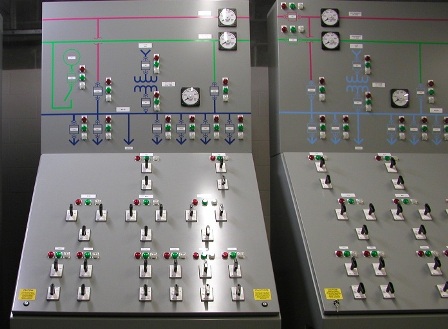
A special place in production program POISK companies occupy control panels for such objects as HPP, NPP, CHPP, GRES ..., called Main control panels (MCU) or Central control panels (CPU). Such shields, in addition to a fairly developed mnemonic circuit, also contain various controls, as well as a large number of measuring / recording devices and digital indicators. Most often, the main control panel / CPU shields are emergency (critical) means of control over the object, therefore, many of the display and control elements on them have direct connections with the equipment they control. Such shields are presented special requirements for design, information content, complexity and reliability.
A kind of control panels are produced by POISK built-in mosaic consoles and control and indication panels... Such panels usually have small size(no more than 2 sq. m.) and are designed to be built into operator / dispatcher consoles or desks.
POISK-SHIELD technology allows you to create dispatch panels ranging from very simple passive (without LED indication and control system) wall panels less than 1 m2 in size, to the most difficult active boards (complexes of visualization of mnemonic circuits) with an area of 100 square meters or more, with a large list of options, equipped with video panels or built-in video walls, extremely saturated with electronic mnemonic symbols and indicators, and also allows you to create video boards (video walls).
POISK is always focused on fulfilling full cycle works covering all stages - from technical advice and design, to installation and commissioning with training. At the same time, to reduce the cost, it is possible to order any set of accessories for self assembly shield or video wall, as well as any amount of work from the complete cycle.
In production video shield(video walls) the POISK company, unlike competitors, offers the customer a full range of services necessary for the full operation of the product (this is enough a rare combination that allows you to get started right away with video shield):
- professional selection, production and delivery of a set of video board equipment (hardware), its assembly and commissioning (including personnel training),
- supply of specialized dispatching software ZNZ of our own design (software part),
- information content of the software part - the creation of an electronic mnemonic diagram (or a complex multilayer project) of the customer's network in the dispatching software ZNZ, as well as its configuration and the necessary initial settings.
POISK has been operating in the electricity market since 1993 and has unique experience in designing more than 400 mnemonic diagrams of various types for all types of power grids, as well as other mnemonic diagrams. The cycle of works offered by the company includes a multi-stage sequential coordination of the electronic mnemonic diagram with the customer during the execution of works, which excludes the possibility of obtaining a negative result at the stage of their acceptance.
All over life cycle of control panels and video panels (video walls) produced by the company SEARCH them accompanies dispatching software ZNZ- developed by POISK company.
POISK has the necessary fleet of modern technological equipment, and own production facilities, providing the POISK-SHIET technology with flexibility, adaptability and versatility, as well as allowing the development and manufacture of original structural elements, incl. corresponding to the individual wishes of the customer.
Just look at the pictures of our billboards / video walls to see how diverse they are. Using various techniques of the SEARCH-SHIELD technology, we give an individual look to each product, but at the same time, the features are traced in all of them. corporate identity. Seeing our billboard or video board, you will always recognize in it a product of the POISK company - a clear, expressive, bright, contrasting mnemonic scheme, high information saturation, a light elegant frame, a well-thought-out, completely finished structure adapted to a specific room, modern finishing materials ...
SEARCH-SHIELD technology provides the highest combination of price, quality and functionality dispatch boards and video walls produced by POISK, which is confirmed by the number of orders we have completed.
This guidance material replaces the guidance material RM 4-65-68 “Drawings of mnemonic diagrams on boards and control panels. Guidelines for registration ". It outlines the basic rules for the implementation of drawings of mnemonic diagrams of control and management systems. The material does not consider the problem of determining the appropriateness of the use of mnemonic diagrams, identifying required type mnemonic diagrams and other tasks solved by designers in the development of functional diagrams of monitoring and control systems.
Since the implementation of mnemonic diagrams is one of the tasks of artistic design, in the solution of which it is necessary to take into account the specific requirements of technical aesthetics and engineering psychology, this material cannot be considered as a document that strictly regulates the design of mnemonic diagrams. It is a design guide and its recommendations must be taken into account in conjunction with other requirements that take place in the design of each specific monitoring and control system.
1. INTRODUCTION
In the mode of non-automatic control of the object, the operator monitors the deviations of the parameters from the preset values. These deviations can be considered as output quantities that change due to changes in the input disturbing influences. Acting on the cause of the deviation, if possible, or on another input quantity, a change in which can compensate for the cause of the deviation (disturbance), the operator controls the object.
From the above, it follows that the operator in the control process needs to identify cause-and-effect relationships to select those controls that will most successfully eliminate unwanted deviations. Since similar deviations of the same parameter can be caused by different reasons - disturbances acting through different channels - inputs, identifying the necessary controls is a difficult task. One of the ways to help the operator in identifying the necessary causal relationships is the use of mnemonic schemes.
Mnemonic diagrams are graphic images of controlled technological objects and, as a rule, should be designed taking into account the requirements of technical aesthetics and engineering psychology. For this reason, in especially critical cases, for example, when designing mnemonic diagrams for typical objects, specialists in artistic design (designers) should take part in their development. The basics of artistic design and ergonomics can be found in the following literature:
1. Johanek T. et al. Technical aesthetics and product culture. M., 1969;
2. Somov Yu.S. Composition in technique. M., 1972;
3. Sidorov O.A. Human physiological factors that determine the layout of the machine control station. M., 1962.
The example of a mnemonic diagram attached to this material is intended only to demonstrate the application of the recommendations of this material in the development of mnemonic diagrams. The types and modifications of accessories used in the example should not be considered as recommended. Their use in the example does not mean that these particular products should be preferred when designing mnemonic diagrams.
2. THE ROLE OF THE MIMS IN THE CONTROL SYSTEM
The logic underlying the measures used by the operator to eliminate abnormal deviations in the course of the technological process is in many ways similar to the logic of the work of a foreman repairing complex electrical and other industrial devices and systems. Knowledge and understanding of the technological scheme of the controlled (or repaired) object is a prerequisite for the successful work of both the operator and the repairer. It is for this reason that for objects with a complex, difficult to remember or operatively changeable technological scheme, it is sometimes advisable to place on the control panel (or console) a conditional simplified graphic image of a controlled technological object, that is, to use a mnemonic scheme.
3. SOME RULES FOR DESIGNING MEMOS
The need to take into account the requirements of technical aesthetics and engineering psychology in the development of mnemonic circuits was indicated in the introduction of this material. From the foregoing it follows that, at least in difficult cases, a specialist in artistic design should participate in the creation of mnemonic diagrams. In simpler cases, the development of mnemonic diagrams is sufficient to carry out, guided by the following rules, the observance of which, usually, gives acceptable results:
a) the mnemonic diagram should not show secondary elements of the technological process that distract the operator's attention and make it difficult to find the information and control bodies he needs;
b) the mnemonic diagram should give the operator the opportunity to quickly assess the overall progress of the process. Therefore, it should reflect all the main contours of control, but the degree of detail should not be excessive, making it difficult to assess the course of the process;
c) the image of the process diagram should be not only beautiful, but also compact enough, visible;
d) the density of symbols placement on the mnemonic diagram field should not be excessive. It should allow making the necessary changes in the future if the production technology is modified (process diagram);
e) the direction of the main technological flow on the mnemonic diagram, as a rule, should be taken in accordance with the generally accepted direction of writing and reading: from left to right;
f) symbols of technological devices related to the same production area should be depicted on the mnemonic diagram field near each other by a common group. Symbols should be approximately evenly spaced within such groups. Such groups should be distinguished by separating them from each other;
g) symbols of technological devices must be placed on the field of the mnemonic diagram in such a way as to minimize the number of intersections of the lines of the mnemonic diagram;
h) the lines of technological streams between the symbols of the apparatus should be carried out along the shortest path, but observing the requirements of p. g;
i) on the lines of technological flows at intervals convenient for the operator, as a rule, near the apparatus, arrows should be placed "direction of flow";
j) all lines of technological streams that do not end with symbols must end with an arrow “direction of flow” and, if necessary, an explanatory inscription ”.
4. SYMBOLS
Symbols of mnemonic schemes are simplified images of technological devices and other devices shown on a mnemonic scheme. The symbols of technological devices, as a rule, should be approximately similar to the corresponding devices.
Compliance with any one scale ratio for the entire mnemonic scheme between the actual dimensions of technological devices and their corresponding symbols, as a rule, is inappropriate.
The sizes (values) of symbols should be taken taking into account the distance of the operator reading the mnemonic diagram. Larger symbols should represent more important devices (if the size of the mnemonic diagram field allows it), which is also necessary when placing control, signaling and control bodies in the symbols.
Minimum permissible character sizes in terms of their legibility by the operator from a distance l, is defined by the following formula:
where S- the size of the symbol;
l- the distance to the symbol along the line of sight (in the same units as S);
a - angle of view (angular size) in arc minutes (").
For symbols not complex shape(there are simple details inside and outside the outline of the symbol) a = 21 "? 1" under normal lighting conditions.
For symbols of complex shape, the value of a should be taken equal to 35 ", for its smallest details -? = 6". The above numbers are minimum. The optimal character size for the fastest reading is? = 40 "The sizes of symbols used in the development of drawings of mnemonic circuits should be checked for their distinguishability from a given reading distance according to the schedule in Appendix 1, built according to formula (1).
The density of symbols on the mnemonic diagram, that is, the distance between adjacent symbols in angular values, must be at least 40 ". Symbols of different technological lines must travel long distances.
Overhead symbols, as a rule, should be made of sheet duralumin with a thickness of 1 - 2 mm. By agreement with the manufacturer of the mimic diagrams, symbols and lines can be made of other materials, for example, of plastics.
Process flow lines, as well as impulse and command lines of devices and regulators, should be depicted by overhead strips of duralumin. It is advisable to take the width of the strips from the range of 4, 6, 8, 10 and 12 mm, and the lines of technological streams should be at least twice as wide as the impulse and command lines. Lines thinner (narrower) 4 mm should be painted (painted lines). At the discretion of the designer, some symbols can be adopted according to the album "Symbols of elements of mnemonic diagrams of boards and control panels" (designations 4.855.600 - 4.855.723), GPI PMA, 1973.
The font sizes of the inscriptions on mnemonic diagrams should be taken taking into account the distances from which these inscriptions will be read. The font size adopted for the inscription should be checked for foresight in accordance with Appendix 2.
5. PAINTS AND COLORS
A wide variety of technological environments and their parameters makes it difficult to standardize the nomenclature of colors and their shades for displaying technological lines and devices on mnemonic circuits. As a rule, the colors of technological devices and lines should approximately coincide with the actual color of technological units and pipelines in accordance with GOST 14202-69 “Pipelines of industrial enterprises. Identification coloring, warning signs and marking plates ”.
The limited range of colors provided by this standard makes it appropriate to use the colors prescribed by these standards, mainly for the depiction of the main technological environments.
Supporting environments have to be depicted with a deviation from the prescriptions of this standard, in accordance with the recommendations of ergonomics specialists and designers of the technological part of the designed object.
As a rule, the pipeline in the diagram is represented by two parallel lines (as a longitudinal section of the pipeline). Since the drawings of mnemonic schemes are usually not colored, then, for the depiction of colors in the drawing, each color representing the technological environment is assigned a number indicating the color (environment), which should be indicated in the breaks of the center lines. The distance between adjacent numbers in the line must be at least 50 mm, see fig. 1a.

a) two-line image, b) single-line image
Numbers denoting colors corresponding to technological environments should be assigned, starting with the main one, in decreasing order of its importance for the technology of the automated process.
Technological lines of mimic diagrams with a width of 4 mm or less are allowed to be depicted as one line, see Fig. 1b.
In view of the wide variety of colors used in mnemonic schemes, it is advisable to use oil artistic paints of the first group according to STU 30-12186-61 for their coloring. Mnemonic schemes using the colors provided for by the nomenclature of paints in GOST 6465-63 and GOST 926-63 can be painted with PF-115 and PF-133 enamels and other enamels suitable for brushing.
6. DRAWING OF THE MEMO DIAGRAM
As a rule, the drawing of the mnemonic diagram should be carried out as a separate drawing on a scale of M1: 2. Other standard scales may only be used in justified cases.
The mnemonic diagram drawing should contain the following information:
a) dimensions mnemonic diagrams and its location on the board or console. Mnemonic diagrams should be located in the zones of the control panel (console) convenient for the operator. If there are controls (keys, buttons) in the mnemonic diagram, the placement of the mnemonic diagram should ensure the convenience of using them. In this case, the controls should be located on the mnemonic diagram at a height of 550 - 1600 mm from the floor level of the control room;
b) a large-scale image of a mnemonic diagram, on which the placement of the main symbols of technological devices is coordinated. It is allowed not to indicate the coordinates of the symbols, if there is an agreement about this with the manufacturer of the mnemonic diagram.
When constructing and placing symbols containing built-in signal lamps, buttons, etc., it is necessary to take into account the design features of built-in products, the possibility and convenience of their installation and maintenance;
c) the colors of all symbols, lines of technological streams, impulse and command lines of devices and regulators. See section 5 of this material for guidance;
d) types, colors and number of lamps, buttons and other products embedded in symbols;
e) explanatory inscriptions, arrows "direction of flow" and, if necessary, designations of monitored measurement points and parameters;
f) position numbers of the mnemonic diagram equipment according to the custom specification and its designation according to the electrical (pneumatic) circuits;
g) the size of the symbols and the material from which they are made;
h) instructions on paints for coloring symbols and lines. See section 5 of this material;
i) numbers of drawings of typical structures;
j) instructions on the attachment of symbols and lines of the mnemonic diagram. As a rule, the choice of the method for attaching the symbols should be provided to the manufacturer, about which an indication is made on the drawing field according to the type: "Fastening the symbols of the mnemonic diagram should be carried out according to the manufacturer's standards."
The main inscription, a list of components, a list of equipment and a table of symbols should be carried out according to the forms of the guidance material RM 4-59-70.
An example of the design of a mnemonic diagram drawing is attached to this guidance material.
Annex 1
The minimum sizes of symbols and their parts depending on the reading distance (see section 4)

Appendix 2
Font size of inscriptions depending on reading distances