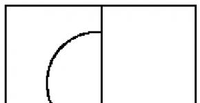
Schematic diagram of an air conditioning system using two-stage evaporative cooling. Central air conditioning systems in buildings p.97 Fig.3
The system under consideration consists of two air conditioners.
the main one, in which the air is processed for the serviced premises, and the auxiliary one - the cooling tower. The main purpose of the cooling tower is air-evaporative cooling of water supplying the first stage of the main air conditioner during the warm period of the year (surface heat exchanger PT). The second stage of the main air conditioner - the OK irrigation chamber, operating in the adiabatic humidification mode, has a bypass channel - bypass B to control the humidity in the room.
In addition to air conditioners - cooling towers, industrial cooling towers, fountains, spray pools, etc. can be used to cool water. In areas with a hot and humid climate, in some cases, in addition to indirect evaporative cooling, machine cooling is used.
multistage systems evaporative cooling. The theoretical limit for air cooling using such systems is the dew point temperature.
Air conditioning systems using direct and indirect evaporative cooling have a wider range of applications compared to systems that use only direct (adiabatic) evaporative cooling.
Two-stage evaporative cooling is known to be the most suitable in
dry and hot regions. With two-stage cooling, more than low temperatures, less air exchanges and lower relative humidity in the rooms than with single-stage cooling. This property two-stage cooling caused a proposal to switch entirely to indirect cooling and a number of other proposals. However, all other things being equal, the effect of possible evaporative cooling systems directly depends on changes in the state of the outside air. Therefore, such systems do not always ensure the maintenance of the required air parameters in air-conditioned rooms during the season and even one day. An idea of the conditions and limits of the expedient use of two-stage evaporative cooling can be obtained by comparing the normalized parameters of indoor air with possible changes in outdoor air parameters in areas with a dry and hot climate.
the calculation of such systems should be carried out with using J-d diagrams in the following order.
On the j-d chart put points with the design parameters of outdoor (H) and indoor (B) air. In the example under consideration, according to the design assignment, the following values are taken: tн = 30 °С; tv = 24 °С; fa = 50%.
For points H and B, we determine the temperature value of the wet bulb:
tmin = 19.72 °С; tmv = 17.0 °C.
As you can see, the value of tmn is almost 3 °C higher than tmv, therefore, for more cooling water and then outer supply air, it is advisable to supply air to the cooling tower, removed exhaust systems from office space.
Note that when calculating the cooling tower, the required air flow may be greater than that removed from the air-conditioned rooms. In this case, a mixture of outside and exhaust air must be supplied to the cooling tower, and the wet bulb temperature of the mixture should be taken as the design value.
From the calculation computer programs of the leading cooling tower manufacturers, we find that the minimum difference between the final temperature of the water at the outlet of the cooling tower tw1 and the wet bulb temperature twm of the air supplied to the cooling tower should be taken as at least 2 °C, i.e.:
tw2 \u003d tw1 + (2.5 ... 3) ° С. (one)
To achieve deeper air cooling in the central air conditioner, the final water temperature at the outlet of the air cooler and at the inlet to the cooling tower tw2 is assumed to be no more than 2.5 higher than at the outlet of the cooling tower, that is:
tvk ≥ tw2 +(1...2) °С. (2)
Note that the final temperature of the cooled air and the surface of the air cooler depend on the temperature tw2, since with a transverse flow of air and water, the final temperature of the cooled air cannot be lower than tw2.
Typically, the final temperature of the cooled air is recommended to be 1-2 °C higher than the final temperature of the water at the outlet of the air cooler:
tvk ≥ tw2 +(1...2) °С. (3)
 Thus, if the requirements (1, 2, 3) are met, it is possible to obtain a dependence that relates the wet bulb temperature of the air supplied to the cooling tower and the final air temperature at the outlet of the cooler:
tvk \u003d tm +6 ° С. (4)
Note that in the example in Fig. 7.14 the values twm = 19 °С and tw2 – tw1 = 4 °С are accepted. But with such initial data, instead of the value tvc = 23 °С indicated in the example, it is possible to obtain a final air temperature at the outlet of the air cooler of at least 26–27 °С, which makes the whole scheme meaningless at tн = 28.5 °С.
In modern climate technology Much attention is paid to the energy efficiency of equipment. This explains the increased Lately interest in water evaporative cooling systems based on indirect evaporative heat exchangers (indirect evaporative cooling systems). Water evaporative cooling systems can be effective solution for many regions of our country, the climate of which is characterized by relatively low humidity. Water as a refrigerant is unique - it has a high heat capacity and latent heat of vaporization, is harmless and affordable. In addition, water is well studied, which makes it possible to accurately predict its behavior in various technical systems.
Features of cooling systems with indirect evaporative heat exchangers
Main Feature and the advantage of indirect evaporative systems is the ability to cool the air to a temperature below the wet bulb temperature. Thus, the technology of conventional evaporative cooling (in adiabatic type humidifiers), when water is injected into the air stream, not only lowers the air temperature, but also increases its moisture content. In this case, the process line on the I d-diagram humid air goes along the adiabat, and the minimum possible temperature corresponds to point "2" (Fig. 1).In indirect evaporative systems, the air can be cooled to point "3" (Fig. 1). The process in the diagram in this case goes vertically down the line of constant moisture content. As a result, the resulting temperature is lower, and the moisture content of the air does not increase (remains constant).
In addition, water evaporation systems have the following positive qualities:
- Possibility of joint production of chilled air and cold water.
- Small power consumption. The main consumers of electricity are fans and water pumps.
- High reliability, due to the absence of complex machines and the use of a non-aggressive working fluid - water.
- Ecological cleanliness: low level noise and vibration, non-aggressive working fluid, low environmental hazard of the industrial production of the system due to the low labor intensity of manufacturing.
- Simplicity of design and relatively low cost associated with the absence of strict requirements for the tightness of the system and its individual components, the absence of complex and expensive machines ( refrigeration compressors), low excess pressures in the cycle, low metal consumption and the possibility of wide use of plastics.
Cooling systems that use the effect of heat absorption during the evaporation of water have been known for a very long time. However, on this moment water-evaporative cooling systems are not widespread enough. Almost the entire niche of industrial and household systems cooling in the region of moderate temperatures is filled with freon vapor compression systems.
This situation is obviously related to the problems of operation of water evaporation systems during negative temperatures and their unsuitability for operation at high relative humidity of the outside air. It also affected the fact that the main apparatus similar systems(cooling towers, heat exchangers), previously used, had large dimensions, weight and other disadvantages associated with working in conditions high humidity. In addition, they needed a water treatment system.
However, today, thanks to technological progress, highly efficient and compact cooling towers have become widespread, capable of cooling water to temperatures that are only 0.8 ... 1.0 ° C different from the wet bulb temperature of the air flow entering the cooling tower.
Here, the cooling towers of the companies Muntes and SRH-Lauer. Such a small temperature difference was achieved mainly due to original design cooling tower nozzles with unique properties— good wettability, manufacturability, compactness.
Description of the indirect evaporative cooling system
In an indirect evaporative cooling system, atmospheric air from environment with parameters corresponding to the point "0" (Fig. 4), is blown into the system by a fan and cooled at a constant moisture content in an indirect evaporative heat exchanger.After the heat exchanger, the main air flow is divided into two: auxiliary and working, directed to the consumer.
The auxiliary flow simultaneously plays the role of both a cooler and a cooled flow - after the heat exchanger it is directed back towards the main flow (Fig. 2).
In this case, water is supplied to the auxiliary flow channels. The meaning of water supply is to "slow down" the increase in air temperature due to its parallel humidification: as you know, the same change in thermal energy can be achieved both by changing only temperature, and by changing temperature and humidity at the same time. Therefore, when the auxiliary flow is humidified, the same heat exchange is achieved with a smaller temperature change.
In indirect evaporative heat exchangers of another type (Fig. 3), the auxiliary flow is not directed to the heat exchanger, but to the cooling tower, where it cools the water circulating through the indirect evaporative heat exchanger: the water is heated in it due to the main flow and cools in the cooling tower due to the auxiliary one. The movement of water along the circuit is carried out using a circulation pump.
Calculation of an indirect evaporative heat exchanger
In order to calculate the cycle of an indirect evaporative cooling system with circulating water, the following input data are needed:- φ os is the relative humidity of the ambient air, %;
- t os - ambient air temperature, ° С;
- ∆t x - temperature difference at the cold end of the heat exchanger, ° С;
- ∆t m - temperature difference at the warm end of the heat exchanger, ° С;
- ∆t wgr is the difference between the temperature of the water leaving the cooling tower and the temperature of the air supplied to it, according to a wet bulb, ° С;
- ∆t min is the minimum temperature difference (temperature difference) between flows in the cooling tower (∆t min<∆t wгр), ° С;
- G p is the mass air flow required by the consumer, kg/s;
- η in - fan efficiency;
- ∆P in - pressure loss in the devices and lines of the system (required fan pressure), Pa.
The calculation methodology is based on the following assumptions:
- The processes of heat and mass transfer are assumed to be equilibrium,
- There are no external heat inflows in all parts of the system,
- The air pressure in the system is equal to atmospheric pressure (local changes in air pressure due to its injection by a fan or passing through aerodynamic resistances are negligible, which allows using the I d diagram of humid air for atmospheric pressure throughout the calculation of the system).
The order of engineering calculation of the system under consideration is as follows (Figure 4):
1. According to the I d diagram or using the program for calculating moist air, additional parameters of the ambient air are determined (point "0" in Fig. 4): specific air enthalpy i 0, J / kg and moisture content d 0, kg / kg.
2. The increase in the specific enthalpy of air in the fan (J/kg) depends on the type of fan. If the fan motor is not blown (not cooled) by the main air flow, then:

If the circuit uses a duct-type fan (when the electric motor is cooled by the main air flow), then:

where:
η dv - efficiency of the electric motor;
ρ 0 - air density at the fan inlet, kg / m 3
![]()
where:
B 0 - barometric pressure of the environment, Pa;
R in - gas constant of air, equal to 287 J / (kg.K).
3. Specific enthalpy of air after the fan (point "1"), J/kg.
i 1 \u003d i 0 + ∆i in; (3)
Since the process "0-1" occurs at a constant moisture content (d 1 \u003d d 0 \u003d const), then according to the known φ 0, t 0, i 0, i 1, we determine the air temperature t1 after the fan (point "1").
4. The dew point of the ambient air t grew, ° С, is determined from the known φ 0, t 0.
5. Psychrometric air temperature difference of the main flow at the outlet of the heat exchanger (point "2") ∆t 2-4, °С
∆t 2-4 =∆t x +∆t wgr; (4)
where:
∆t x is assigned based on specific operating conditions in the range ~ (0.5…5.0), °C. In this case, it should be borne in mind that small values of ∆t x will entail relatively large dimensions of the heat exchanger. To ensure small values of ∆t x, it is necessary to use highly efficient heat transfer surfaces;
∆t wgr is selected in the range (0.8…3.0), °С; smaller values of ∆t wgr should be taken if it is necessary to obtain the lowest possible temperature of cold water in the cooling tower.
6. We accept that the process of moistening the auxiliary air flow in the cooling tower from the state "2-4", with sufficient accuracy for engineering calculations, goes along the line i 2 =i 4 =const.
In this case, knowing the value of ∆t 2-4, we determine the temperatures t 2 and t 4, points "2" and "4", respectively, °C. To do this, we will find such a line i=const, so that between the point "2" and the point "4" the temperature difference is the found ∆t 2-4. Point "2" is located at the intersection of the lines i 2 =i 4 =const and constant moisture content d 2 =d 1 =d OS. Point "4" is at the intersection of the line i 2 =i 4 =const and the curve φ 4 = 100% relative humidity.
Thus, using the above diagrams, we determine the remaining parameters at points "2" and "4".
7. Determine t 1w — the temperature of the water at the outlet of the cooling tower, at the point "1w", °C. In the calculations, we can neglect the heating of water in the pump, therefore, at the inlet to the heat exchanger (point "1w '"), the water will have the same temperature t 1w
t 1w \u003d t 4 +.∆t wgr; (5)
8. t 2w - water temperature after the heat exchanger at the inlet to the cooling tower (point "2w"), °С
t 2w \u003d t 1 -.∆t m; (6)
9. The temperature of the air discharged from the cooling tower into the environment (point "5") t 5 is determined by the graphical-analytical method using the id diagram (with great convenience, a combination of Q t and i t-diagrams can be used, however, they are less common, therefore, in this id diagram was used in the calculation). This method is as follows (Fig. 5):
- point "1w", characterizing the state of water at the inlet to the indirect evaporative heat exchanger, with the value of the specific enthalpy of point "4" is placed on the isotherm t 1w, spaced from the isotherm t 4 at a distance ∆t wgr.
- From the point "1w" along the isenthalpe we set aside the segment "1w - p" so that t p \u003d t 1w - ∆t min.
- Knowing that the process of air heating in the cooling tower occurs according to φ=const=100%, we build a tangent to φ pr =1 from the point "p" and get the tangent point "k".
- From the point of contact “k” along the isoenthalpe (adiabatic, i = const), we set aside the segment “k - n” so that t n \u003d t k + ∆t min. Thus, the minimum temperature difference between the cooled water and the auxiliary flow air in the cooling tower is ensured (assigned). This temperature difference ensures that the cooling tower operates in the design mode.
- We draw a straight line from the point "1w" through the point "n" to the intersection with the straight line t=const= t 2w . We get the point "2w".
- From the point "2w" draw a straight line i=const to the intersection with φ pr =const=100%. We get the point "5", which characterizes the state of the air at the outlet of the cooling tower.
- According to the diagram, we determine the desired temperature t5 and the remaining parameters of point "5".
10. We compose a system of equations for finding unknown mass flow rates of air and water. Thermal load of the cooling tower by auxiliary air flow, W:
Q gr \u003d G in (i 5 - i 2); (7)
Q wgr \u003d G ow C pw (t 2w - t 1w) ; (8)
where:
C pw is the specific heat capacity of water, J/(kg.K).
Heat load of the heat exchanger for the main air flow, W:
Q mo =G o (i 1 - i 2) ; (9)
Thermal load of the heat exchanger in terms of water flow, W:
Q wmo =G ow C pw (t 2w - t 1w) ; (10)
Material balance by air flow:
G o =G to +G p ; (11)
Thermal balance over the cooling tower:
Q gr =Q wgr; (12)
The heat balance of the heat exchanger as a whole (the amount of heat transferred by each of the flows is the same):
Q wmo = Q mo ; (13)
Combined heat balance of cooling tower and heat exchanger for water:
Q wgr =Q wmo ; (14)
11. Solving together the equations from (7) to (14), we obtain the following dependencies:
mass air flow in the auxiliary flow, kg/s:
![]()
mass air flow in the main air flow, kg/s:
G o =G p ; (16)
Mass flow of water through the cooling tower along the main flow, kg/s:
![]()
12. The amount of water required to feed the water circuit of the cooling tower, kg/s:
G wn \u003d (d 5 -d 2) G in; (18)
13. Power consumption in the cycle is determined by the power spent on the fan drive, W:
N in =G o ∆i in; (19)
Thus, all the parameters necessary for constructive calculations of the elements of the indirect evaporative air cooling system have been found.
It should be noted that the working stream of cooled air supplied to the consumer (point "2") can be additionally cooled, for example, by adiabatic humidification or by any other method. As an example, in fig. 4 shows the point "3*" corresponding to adiabatic humidification. In this case, the points "3*" and "4" coincide (Fig. 4).
Practical aspects of indirect evaporative cooling systems
Based on the practice of calculating indirect evaporative cooling systems, it should be noted that, as a rule, the auxiliary flow rate is 30-70% of the main flow and depends on the potential cooling capacity of the air supplied to the system.If we compare cooling by adiabatic and indirect evaporative methods, then from the I d-diagram it can be seen that in the first case, air with a temperature of 28 ° C and a relative humidity of 45% can be cooled to 19.5 ° C, while in the second case — up to 15°С (Fig. 6).
"Pseudo-indirect" evaporation
As mentioned above, the indirect evaporative cooling system allows you to achieve a lower temperature than the traditional adiabatic air humidification system. It is also important to emphasize that the moisture content of the desired air does not change. Similar advantages compared to adiabatic humidification can be achieved by introducing an auxiliary air flow.
There are currently few practical applications of the indirect evaporative cooling system. However, devices of a similar, but somewhat different principle of operation have appeared: air-to-air heat exchangers with adiabatic humidification of the outside air (systems of "pseudo-indirect" evaporation, where the second flow in the heat exchanger is not some moistened part of the main flow, but another, absolutely independent circuit).
Such devices are used in systems with a large volume of recirculated air that needs to be cooled: in air conditioning systems of trains, auditoriums for various purposes, data centers and other facilities.
The purpose of their introduction is the maximum possible reduction in the duration of operation of energy-intensive compressor refrigeration equipment. Instead, for outside temperatures up to 25°C (and sometimes even higher), an air-to-air heat exchanger is used in which the recirculated room air is cooled by the outside air.
For greater efficiency of the device, the outside air is pre-moistened. In more complex systems, humidification is also carried out in the process of heat exchange (injection of water into the channels of the heat exchanger), which further increases its efficiency.
Thanks to the use of such solutions, the current energy consumption of the air conditioning system is reduced by up to 80%. The total annual energy consumption depends on the climatic region of the system operation, on average it is reduced by 30-60%.
Yury Khomutsky, technical editor of the magazine "Climate World"
The article uses the methodology of Moscow State Technical University. N. E. Bauman for the calculation of an indirect evaporative cooling system.
For servicing individual small rooms or groups of them, local air conditioners of two-stage evaporative cooling are convenient, carried out on the basis of an indirect evaporative cooling heat exchanger made of aluminum rolling tubes (Fig. 139). The air is cleaned in the filter 1 and enters the fan 2, after the discharge opening of which it is divided into two flows - main 3 and auxiliary 6. The auxiliary air flow passes inside the tubes of the heat exchanger 14 of indirect evaporative cooling and provides evaporative cooling of the water flowing down the inner walls of the tubes. The main air flow passes from the side of the fins of the heat exchanger tubes and gives off heat through their walls to the water cooled by evaporation. Water recirculation in the heat exchanger is carried out using pump 4, which takes water from the sump 5 and supplies it for irrigation through perforated pipes 15. The heat exchanger for indirect evaporative cooling plays the role of the first stage in combined air conditioners of two-stage evaporative cooling.
Ecology of consumption. The history of the direct evaporative air conditioner. Differences between direct and indirect cooling. Evaporative Air Conditioner Applications
Cooling and humidifying the air through evaporative cooling is a completely natural process in which water is used as a cooling medium and heat is efficiently dissipated in the atmosphere. Simple laws are used - when a liquid evaporates, heat is absorbed or cold is released. Evaporation efficiency - increases with increasing air speed, which provides forced circulation of the fan.
The temperature of dry air can be substantially lowered by the phase change of liquid water into steam, and this process requires much less energy than compression cooling. In very dry climates, evaporative cooling also has the advantage of increasing the humidity of the air when it is conditioned, and this creates more comfort for the people in the room. However, unlike vapor compression refrigeration, it requires a constant source of water, and during operation it constantly consumes it.
The history of development
For centuries, civilizations have found original methods of dealing with the heat in their territories. An early form of cooling system, the "wind catcher", was invented many thousands of years ago in Persia (Iran). It was a system of wind shafts on the roof that caught the wind, passed it through the water, and blew cool air into the interior. It is noteworthy that many of these buildings also had yards with large water supplies, so if there was no wind, then as a result of the natural process of water evaporation, hot air, rising up, evaporated water in the yard, after which the already cooled air passed through the building. Today, Iran has replaced wind catchers with evaporative coolers and uses them extensively, and the market due to the dry climate reaches a turnover of 150,000 evaporators per year.
In the US, the evaporative cooler has been the subject of numerous patents in the twentieth century. Many of whom, since 1906, have proposed the use of wood shavings as a pad to carry a large amount of water in contact with moving air, and to support intense evaporation. The standard design, as shown in the 1945 patent, includes a water reservoir (usually fitted with a float valve for level control), a pump to circulate water through the wood chip spacers, and a fan to blow air through the spacers into the living quarters. This design and materials remain central to evaporative cooler technology in the US Southwest. In this region, they are additionally used to increase humidity.
Evaporative cooling was common in aircraft engines of the 1930s, such as the engine for the airship Beardmore Tornado. This system was used to reduce or completely eliminate the radiator, which otherwise could create significant aerodynamic drag. In these systems, the water in the engine was pressurized with pumps that allowed it to heat up to over 100°C, since the actual boiling point is pressure dependent. Superheated water was sprayed through a nozzle onto an open pipe, where it instantly evaporated, taking its heat. These tubes could be located below the surface of the aircraft to create zero drag.
External evaporative cooling devices have been installed on some vehicles to cool the passenger compartment. Often they were sold as additional accessories. The use of evaporative cooling devices in automobiles continued until vapor compression air conditioning became widespread.
The principle of evaporative cooling is different from that of vapor compression refrigeration, although they also require evaporation (evaporation is part of the system). In a vapor compression cycle, after the refrigerant inside the evaporator coil has evaporated, the refrigerant gas is compressed and cooled, condensing under pressure into a liquid state. Unlike this cycle, in an evaporative cooler, water is evaporated only once. The evaporated water in the cooling device is discharged into the space with cooled air. In the cooling tower, the evaporated water is carried away by the air flow.
Evaporative Cooling Applications
Distinguish evaporative air cooling direct, oblique, and two-stage (direct and indirect). Direct evaporative air cooling is based on the isenthalpy process and is used in air conditioners during the cold season; in warm weather, it is possible only if there is no or slight moisture release in the room and a low moisture content of the outside air. Bypassing the irrigation chamber somewhat expands the boundaries of its application.
Direct evaporative air cooling is advisable in dry and hot climates in the supply ventilation system.
Indirect evaporative air cooling is carried out in surface air coolers. An auxiliary contact apparatus (cooling tower) is used to cool the water circulating in the surface heat exchanger. For indirect evaporative cooling of the air, it is possible to use devices of the combined type, in which the heat exchanger performs both functions simultaneously - heating and cooling. Such devices are similar to air recuperative heat exchangers.
Cooled air passes through one group of channels, the inner surface of the second group is irrigated with water flowing into the pan, and then sprayed again. Upon contact with the exhaust air passing in the second group of channels, evaporative cooling of the water occurs, as a result of which the air in the first group of channels is cooled. Indirect evaporative air cooling makes it possible to reduce the performance of the air conditioning system compared to its performance with direct evaporative air cooling and expands the possibilities of using this principle, because. the moisture content of the supply air in the second case is less.
With two-stage evaporative cooling air use sequential indirect and direct evaporative cooling of the air in the air conditioner. At the same time, the installation for indirect evaporative air cooling is supplemented with an irrigation nozzle chamber operating in the direct evaporative cooling mode. Typical spray nozzle chambers are used in evaporative air cooling systems as cooling towers. In addition to single-stage indirect evaporative air cooling, a multi-stage one is possible, in which deeper air cooling is carried out - this is the so-called compressorless air conditioning system.
Direct evaporative cooling (open cycle) is used to reduce the air temperature using the specific heat of evaporation, changing the liquid state of water to a gaseous one. In this process, the energy in the air does not change. Dry, warm air is replaced by cool, moist air. The heat from the outside air is used to evaporate the water.
Indirect evaporative cooling (closed loop) is a process similar to direct evaporative cooling, but using a certain type of heat exchanger. In this case, moist, cooled air does not come into contact with the conditioned environment.
Two-stage evaporative cooling, or indirect/direct.
Traditional evaporative coolers use only a fraction of the energy needed by vapor compression refrigeration or adsorption air conditioning systems. Unfortunately, they raise the humidity to an uncomfortable level (except in very dry climates). Two-stage evaporative coolers do not increase humidity levels as much as standard single-stage evaporative coolers do.
In the first stage of a two-stage cooler, the warm air is cooled indirectly without increasing humidity (by passing through a heat exchanger cooled by evaporation from the outside). In the direct stage, pre-cooled air passes through the water-soaked pad, cools down further, and becomes more humid. Since the process includes a first, pre-cooling stage, the direct evaporation stage requires less moisture to reach the required temperatures. As a result, according to manufacturers, the process cools air with relative humidity in the range of 50 to 70%, depending on the climate. In comparison, traditional cooling systems raise the humidity of the air to 70 - 80%.
Purpose
When designing a central supply ventilation system, it is possible to equip the air intake with an evaporative section and thus significantly reduce the cost of air cooling in the warm season.
In the cold and transitional periods of the year, when air is heated by supply heaters of ventilation systems or indoor air by heating systems, the air heats up and its physical ability to assimilate (absorb) into itself increases, with an increase in temperature - moisture. Or, the higher the air temperature, the more moisture it can assimilate into itself. For example, when the outside air is heated by a heater with a ventilation system from a temperature of -22 0 C and a humidity of 86% (outside air parameter for the KhP of Kiev), to +20 0 C - the humidity drops below the boundary limits for biological organisms to unacceptable 5-8% air humidity. Low air humidity - negatively affects the skin and mucous membranes of a person, especially those with asthma or lung diseases. Air humidity normalized for residential and administrative premises: from 30 to 60%.
Evaporative air cooling is accompanied by the release of moisture or an increase in air humidity, up to a high saturation of air humidity of 60-70%.
Advantages
The amount of evaporation – and thus heat transfer – depends on the outside wet bulb temperature which, especially in summer, is much lower than the equivalent dry bulb temperature. For example, on hot summer days when dry bulb temperatures exceed 40°C, evaporative cooling can cool water down to 25°C or cool air.
Since evaporation removes much more heat than standard sensible heat transfer, heat transfer uses four times less air than conventional air cooling methods, saving a significant amount of energy.
Evaporative cooling versus conventional air conditioning Unlike other types of air conditioning, evaporative air cooling (bio-cooling) does not use harmful gases (freon and others) as refrigerants that harm the environment. It also consumes less electricity, thus saving energy, natural resources and up to 80% of operating costs compared to other air conditioning systems.
Flaws
Poor performance in humid climates.
An increase in air humidity, which in some cases is undesirable - the output is a two-stage evaporation, where the air does not come into contact and is not saturated with moisture.
Principle of operation (option 1)
The cooling process is carried out due to the close contact of water and air, and the transfer of heat into the air by evaporating a small amount of water. Further, the heat is dissipated through the warm and moisture-saturated air leaving the unit.
Principle of operation (option 2) - installation on the air intake
Evaporative Cooling Plants
There are different types of evaporative cooling units, but they all have:
- a heat exchange or heat transfer section permanently wetted with water by spraying,
- a fan system for forced circulation of outside air through the heat exchange section,
When building processes on the i - d diagram and choosing a technological scheme for air treatment, it is necessary to strive for the rational use of energy, ensuring the economical use of cold, heat, electricity, water, as well as saving the construction area occupied by the equipment. To this end, it is necessary to analyze the possibility of saving artificial cold through the use of direct and indirect evaporative air cooling, the use of a scheme with the heat recovery of the exhaust air and the utilization of heat from secondary sources, if necessary, the use of the first and second air recirculation, a bypass scheme, as well as controlled processes in heat exchangers.
Recirculation is used in rooms with significant heat surpluses, when the supply air flow rate, determined for the removal of excess heat, is greater than the required outdoor air flow rate. During the warm period of the year, recirculation makes it possible to reduce the costs of cold compared to a once-through scheme of the same capacity, if the enthalpy of the outside air is higher than the enthalpy of the exhaust air, and also to abandon the second heating. In the cold period - significantly reduce the cost of heat for heating the outside air. When using evaporative cooling, when the enthalpy of the outdoor air is lower than that of the indoor and exhaust air, recirculation is not advisable. The movement of recirculated air through the duct network is always associated with additional energy costs, it requires a building volume to accommodate recirculation ducts. Recirculation will be expedient if the costs of its installation and operation are less than the resulting savings in heat and cold. Therefore, when determining the supply air flow rate, one should always strive to bring it closer to the minimum required value of outdoor air, taking the appropriate air distribution scheme in the room and the type of air terminal and, accordingly, the once-through scheme. Recirculation is also not compatible with the heat recovery of the exhaust air. In order to reduce heat consumption for heating outdoor air during the cold season, it is necessary to analyze the possibility of using secondary heat from low-potential sources, namely: etc. Exhaust air heat recovery heat exchangers also make it possible to somewhat reduce the consumption of cold during the warm season in areas with a hot climate.
To make the right choice, you need to know the possible air treatment schemes and their features. Consider the simplest processes of changing the state of air and their sequence in central air conditioners serving one large room.
Usually, the determining mode for choosing a technological scheme for processing and determining the performance of an air conditioning system is the warm period of the year. In the cold period of the year, they strive to maintain the supply air flow determined for the warm period of the year and the air treatment scheme.
Two-stage evaporative cooling
The wet bulb temperature of the main air flow after cooling in the surface heat exchanger of indirect evaporative cooling has a lower value compared to the outdoor air wet bulb temperature, as a natural limit of evaporative cooling. Therefore, during the subsequent processing of the main flow in the contact apparatus by direct evaporative cooling, it is possible to obtain lower air parameters compared to the natural limit. Such a scheme of sequential air treatment of the main air flow by the method of indirect and direct evaporative cooling is called two-stage evaporative cooling. The layout diagram of the central air conditioner equipment, corresponding to the two-stage evaporative air cooling, is shown in Figure 5.7 a. It is also characterized by the presence of two air flows: main and auxiliary. The outdoor air, which has a lower wet bulb temperature than the indoor air in the serviced room, enters the main air conditioner. In the first air cooler, it is cooled by indirect evaporative cooling. Then it enters the adiabatic humidification unit, where it is cooled and humidified. Evaporative cooling of water circulating through the surface air coolers of the main air conditioner is carried out when it is sprayed in the adiabatic humidification unit in the auxiliary flow. The circulation pump takes water from the sump of the auxiliary flow adiabatic humidification unit and supplies it to the air coolers of the main flow and further - for spraying in the auxiliary flow. The loss of water from evaporation in the main and auxiliary flow is replenished through the float valves. After two stages of cooling, air is supplied to the room.