GOST conventional graphic designations in electrical diagrams. Graphic symbols on electrical schematic diagrams
Almost all UOS, all electronic and electrical products manufactured industrial organizations and enterprises, home craftsmen, young technicians and radio amateurs, contain in their composition a certain amount of various purchased ERI and elements produced mainly by the domestic industry. But for recent times there is a tendency to use ERE and foreign-made components. These include, first of all, PPP, capacitors, resistors, transformers, chokes, electrical connectors, batteries, HIT, switches, installation products and some other types of ERE.
Applied purchased components or independently manufactured EREs will necessarily be reflected in the basic and installation electrical diagrams devices, in the drawings and other TD, which are carried out in accordance with the requirements of the ESKD standards.
Particular attention is paid to circuit diagrams, which determine not only the basic electrical parameters, but also all the elements included in the device and the electrical connections between them. To understand and read the circuit diagrams, you must carefully familiarize yourself with the elements and components included in them, know exactly the scope and principle of operation of the device in question. As a rule, information about the ERE used is indicated in reference books and specifications - a list of these elements.
The connection of the list of ERE components with their conventional graphic designations is carried out through reference designations.
To construct conventional graphic symbols for ERE, standardized geometric symbols are used, each of which is used separately or in combination with others. Moreover, the meaning of each geometric image in symbol in many cases depends on the combination with which other geometric symbol it is used.
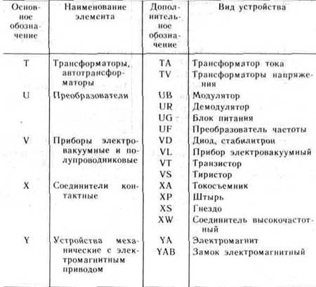
Standardized and most commonly used conditional graphic symbols ERE in basic electrical circuits are shown in Fig. 1. 1. These designations relate to all component elements of the circuits, including ERE, conductors and connections between them. And here the condition for the correct designation of the same type of ERE components and products is of paramount importance. For this purpose, reference designations are used, a mandatory part of which is the letter designation of the type of element, the type of its design and the digital designation of the ERE number. The diagrams also use the additional part of the designation of the ERE position, indicating the function of the element, in the form of a letter. The main types of letter designations of circuit elements are given in table. 1.1.
Designations in the drawings and diagrams of elements of general use refer to qualification ones that establish the type of current and voltage. type of connection, control methods, pulse shape, type of modulation, electrical connections, direction of transmission of current, signal, energy flow, etc.
Currently, the population and the trading network are in operation a significant number of various electronic devices and devices, radio and television equipment, which are manufactured by foreign firms and various joint stock companies... In stores you can buy Various types ERI and ERE with foreign designations. Table 1.2 provides information about the most common ERE foreign countries with the appropriate designations and their counterparts of domestic production.
This information is published for the first time in such a volume.
1- pnp structure transistor in a package, general designation;
2- transistor of structure n-p-n in a package, general designation,
3 - field-effect transistor with p-n junction and n channel,
4 - field-effect transistor with p-n junction and p channel,
5 - unijunction transistor with base n type, b1, b2 - base terminals, e - emitter output,
6 - photodiode,
7 - rectifier diode,
8 - one-way zener diode (avalanche rectifier diode),
9 - heat-electric diode,
10 - diode dinistor, lockable in the opposite direction;
11 - zener diode (diode avalanche rectifier) with double-sided conductivity,
12 - triode thyristor;
13 - photoresistor;
14 - variable resistor, rheostat, general designation,
15 - variable resistor,
16 - variable resistor with taps,
17 - trimmer potentiometer;
18 - thermistor with a positive temperature coefficient of direct heating (heating),
19 - varistor;
20 - constant capacitor, general designation;
21 - polarized fixed capacitor;
22 - polarized electrolytic oxide capacitor, general designation;
23 - constant resistor, general designation;
24 - constant resistor with a rated power of 0.05 W;
25 - constant resistor with a rated power of 0, 125 W,
26 - constant resistor with a rated power of 0.25 W,
27 - constant resistor with a rated power of 0.5 W,
28 - constant resistor with a rated power of 1 W,
29 - constant resistor with a rated power dissipation of 2 W,
30 - constant resistor with a rated power dissipation of 5 W;
31 - constant resistor with one symmetrical additional tap;
32 - constant resistor with one asymmetrical additional tap;

Fig 1.1 Symbols of ERE in electrical, radio engineering and automation circuits
33 - non-polarized oxide capacitor;
34 - pass-through capacitor (arc denotes a housing, an external electrode);
35 - variable capacitor (arrow indicates the rotor);
36 - trimmer capacitor, general designation;
37 - varicond;
38 - noise suppression capacitor;
39 - LED;
40 - tunnel diode;
41 - lighting and signal incandescent lamp;
42 - electric bell;
43 - galvanic or battery cell;
44 - electrical communication line with one branch;
45 - electrical communication line with two branches;
46 - a group of wires connected to one point electrical connection... Two wires;
47 - four wires connected to one electrical connection point;
48 - a battery of galvanic cells or a rechargeable battery;
49 - coaxial cable. The screen is connected to the body;
50 - winding of a transformer, autotransformer, choke, magnetic amplifier;
51 - working winding of the magnetic amplifier;
52 - control winding of the magnetic amplifier;
53 - transformer without a core (magnetic circuit) with permanent coupling (the dots indicate the beginning of the windings);
54 - transformer with a magnetodielectric core;
55 - inductor coil, choke without magnetic circuit;
56 - single-phase transformer with a ferromagnetic magnetic circuit and a screen between the windings;
57 - single-phase three-winding transformer with a ferromagnetic magnetic circuit with a tap in the secondary winding;
58 - single-phase autotransformer with voltage regulation;
59 - fuse;
60 - fuse switch;
61 - fuse disconnector;
62 - detachable pin connection;
63 - amplifier (the direction of signal transmission is indicated by the apex of the triangle on the horizontal communication line);
64 - pin of detachable contact connection;

Fig 1.1 Symbols of ERE in electrical radio engineering and automation circuits
65 - socket of a detachable contact connection,
66 - contact collapsible connection for example with a clamp
67 - contact of a non-separable connection, for example carried out by soldering
68 - push-button single-pole push-button switch with self-resetting closing contact
69 - contact of the switching device opening, general designation
70 - closing contact of a switching device (switch, relay), general designation. The switch is single-pole.
71 - changeover contact of the switching device, general designation. Single-pole, two-way switch.
72- three-position changeover contact with neutral position
73 - closing contact without self-return
74 - push-button switch with break contact
75 - push-button exhaust switch with NO contact
76 - push-button switch with push-button return,
77 - push-button exhaust switch with break contact
78 - push-button switch with return by pressing the button a second time,
79 - electrical relay with normally open and changeover contacts,
80 - relay polarized in one direction of current in a winding with a neutral position
81 - relay polarized in both directions of current in a winding with a neutral position
82 - electric thermal relay without self-return, with a return by pressing the button a second time,
83 - detachable single-pole connection
84 - socket of a five-wire pin detachable connection
85 - pin of the pin detachable coaxial connection
86 - socket of contact connection
87 - pin four-wire connection
88 - socket of a four-wire connection
89 - jumper switching opening circuit
Table 1.1. Letter designations of circuit elements

Continuation of table 1.1

Any electrical circuits can be presented in the form of drawings (schematic and wiring diagrams), the design of which must comply with ESKD standards. These standards apply to both wiring or power circuits and electronic devices. Accordingly, in order to "read" such documents, it is necessary to understand the symbols in the electrical circuits.
Regulations
Given the large number of electrical elements, for their alphanumeric (hereinafter BO) and conventionally graphic designations (UGO), a number of regulatory documents have been developed to exclude discrepancy. Below is a table showing the main standards.
Table 1. Standards for graphic designation individual elements in installation and circuit diagrams.
| GOST number | Short description |
| 2.710 81 | This document contains the requirements of GOST for BO of various types of electrical elements, including electrical appliances. |
| 2.747 68 | Requirements for the size of displaying elements in graphical form. |
| 21.614 88 | Accepted standards for electrical plans and wiring. |
| 2.755 87 | Display on diagrams of switching devices and contact connections |
| 2.756 76 | Standards for sensing parts of electromechanical equipment. |
| 2.709 89 | This standard regulates the standards according to which the contact connections and wires are indicated on the diagrams. |
| 21.404 85 | Schematic symbols for equipment used in automation systems |
It should be borne in mind that the element base changes over time, accordingly changes are made to the regulatory documents, although this process is more inert. Let's give a simple example, RCDs and difavtomats have been widely used in Russia for more than a decade, but there is still no single standard for these devices in accordance with GOST 2.755-87, in contrast to circuit breakers... It is quite possible that this issue will be settled in the near future. To keep abreast of such innovations, professionals track changes in regulatory documents, for amateurs it is not necessary to do this, it is enough to know the decoding of the basic designations.
Types of electrical circuits
In accordance with the norms of ESKD, diagrams are graphic documents on which, using adopted designations the main elements or nodes of the structure are displayed, as well as the links uniting them. According to the accepted classification, ten types of circuits are distinguished, of which three are most often used in electrical engineering:
If the diagram shows only the power part of the installation, then it is called single-line, if all the elements are shown, then it is complete.


If the drawing shows the wiring of the apartment, then the locations lighting fixtures, sockets and other equipment are indicated on the plan. Sometimes you can hear how such a document is called a power supply scheme, this is incorrect, since the latter reflects the way consumers are connected to a substation or other power source.
Having dealt with the electrical circuits, we can proceed to the designations of the elements indicated on them.
Graphic symbols
For each type graphic document their designations are provided, regulated by the relevant regulatory documents. Let us give as an example the main graphic symbols for different types electrical circuits.
Examples of UGO in functional diagrams
Below is a figure depicting the main nodes of automation systems.
 Examples of symbols for electrical appliances and automation equipment in accordance with GOST 21.404-85
 Description of designations:
- A - Basic (1) and allowed (2) images of devices that are installed outside the electrical panel or junction box.
- B - Same as point A, except that the elements are located on the control panel or electrical panel.
- С - Display of executive mechanisms (MI).
- D - Influence of IM on the regulatory body (hereinafter RO) when the power is turned off:
- Opening of RO
- Closing RO
- The position of the RO remains unchanged.
- E - IM, on which a manual drive is additionally installed. This symbol can be used for any position of the RO specified in clause D.
- F- Received communication lines display:
- General.
- There is no connection at the intersection.
- The presence of a connection at the intersection.
UGO in single-line and complete wiring diagrams
There are several groups of symbols for these schemes, we will give the most common of them. To receive complete information it is necessary to refer to the regulatory documents, numbers state standards will be given for each group.
Power supplies.
For their designation, the symbols shown in the figure below are adopted.
 UGO power supplies on schematic diagrams(GOST 2.742-68 and GOST 2.750.68)
 Description of designations:
- A - source with constant voltage, its polarity is indicated by the symbols "+" and "-".
- V is the electricity icon representing alternating voltage.
- C - the symbol for alternating and direct voltage, used in cases where the device can be powered from any of these sources.
- D - Display battery or galvanic power supply.
- E- Symbol for a multi-cell battery.
Communication lines
The basic elements of electrical connectors are shown below.
 Designation of communication lines on schematic diagrams (GOST 2.721-74 and GOST 2.751.73)
 Description of designations:
- A - General mapping adopted for different types electrical connections.
- B - Current-carrying or grounding bus.
- C - Designation of shielding, can be electrostatic (marked with the symbol "E") or electromagnetic ("M").
- D - Grounding symbol.
- E - Electrical connection with the body of the device.
- F - On complex schemes, of several component parts, thus a break in communication is indicated, in such cases "X" is information about where the line will be extended (as a rule, the element number is indicated).
- G - Intersection with no connection.
- H - Connection at the intersection.
- I - Branches.
Designations of electromechanical devices and contact connections
Examples of designation of magnetic starters, relays, as well as contacts of communication devices can be found below.
 UGO, adopted for electromechanical devices and contactors (GOST 2.756-76, 2.755-74, 2.755-87)
 Description of designations:
- A - symbol of the coil of an electromechanical device (relay, magnetic starter, etc.).
- B - UGO of the receiving part of the electrical thermal protection.
- С - display of the coil of the device with mechanical interlock.
- D - contacts of switching devices:
- Closing.
- Openers.
- Switching.
- E - Symbol for designation of manual switches (buttons).
- F - Group switch (switch).
UGO electric machines
Here are some examples, mapping electric cars(hereinafter EM) in accordance with the current standard.
 Designation of electric motors and generators on schematic diagrams (GOST 2.722-68)
 Description of designations:
- A - three-phase EM:
- Asynchronous (short-circuited rotor).
- Same as point 1, only in two-speed version.
- Asynchronous EMs with phase rotor design.
- Synchronous motors and generators.
- B - Collector, DC powered:
- EM with permanent magnet excitation.
- EM with an excitation coil.

UGO transformers and chokes
Examples of graphical symbols for these devices can be found in the figure below.
Description of designations:
- A - This graphic symbol can indicate inductors or transformer windings.
- B - Choke, which has a ferrimagnetic core (magnetic circuit).
- C - Display of a two-coil transformer.
- D - Device with three coils.
- E - Autotransformer symbol.
- F - Graphic display of CT (current transformer).
Designation of measuring devices and radio components
A brief overview of the UGO data of electronic components is shown below. For those who want to become more familiar with this information, we recommend that you look through GOSTs 2.729 68 and 2.730 73.
 Examples of graphic symbols for electronic components and measuring instruments
Description of designations:
- Electricity meter.
- Image of an ammeter.
- Mains voltage measuring device.
- Thermal sensor.
- Constant value resistor.
- Variable resistor.
- Condenser (general designation).
- Electrolytic capacity.
- Diode designation.
- Light-emitting diode.
- Image of a diode optocoupler.
- UGO transistor (in this case npn).
- Fuse designation.
UGO lighting fixtures
Consider how electric lamps are displayed on a schematic diagram.

Description of designations:
- A - General image of incandescent lamps (LN).
- B - LN as a signaling device.
- C - Type designation of discharge lamps.
- D - Gas discharge light source high blood pressure(the figure shows an example of a design with two electrodes)
Designation of elements in the wiring diagram
Completing the topic of graphic symbols, we give examples of the display of sockets and switches.

As depicted, sockets of other types are easy to find in the regulatory documents that are available on the network.


The ability to read electrical circuits is an important component, without which it is impossible to become a specialist in the field electrical work... Every novice electrician must know how sockets, switches, switching devices and even an electricity meter are indicated on the wiring project in accordance with GOST. Further, we will provide the readers of the site with symbols in electrical circuits, both graphical and alphabetic.
Graphic
As for the graphic designation of all elements used in the diagram, we will provide this overview in the form of tables, in which the products will be grouped by purpose.
In the first table you can see how marked electrical boxes, boards, cabinets and consoles on wiring diagrams:
The next thing you need to know is the conventional designation of power outlets and switches (including walk-through switches) on single-line diagrams of apartments and private houses:

With regard to lighting elements, lamps and lamps in accordance with GOST indicate as follows:


In more complex circuits where electric motors are used, elements such as:

It is also useful to know how transformers and chokes are graphically indicated on schematic wiring diagrams:

Electrical measuring instruments in accordance with GOST have the following graphic designations in the drawings:

And here, by the way, is a table useful for novice electricians, which shows how the ground loop looks like on the wiring plan, as well as the power line itself:

In addition, on the diagrams you can see a wavy or straight line, "+" and "-", which indicate the type of current, voltage and pulse shape:

In more complex automation schemes, you can find incomprehensible graphic symbols, such as contact connections. Remember how these devices are indicated on the wiring diagrams:


In addition, you should be aware of how radioelements look on projects (diodes, resistors, transistors, etc.):

That's all the conventionally graphic designations in the electrical circuits of power circuits and lighting. As you have already seen for yourself, there are quite a few components and you can remember how each is designated only with experience. Therefore, we recommend that you keep all these tables for yourself, so that when reading the draft of the layout of the wiring of a house or apartment, you can immediately determine what kind of circuit element is in a certain place.
Interesting video
Built on the basis of the symbols of contacts: closing (Fig. 1, b), opening (c, d) and switching (d, f). Contacts that simultaneously close or open two circuits are designated, as shown in Fig. 1, (g, u and).
For the initial position of the closing contacts on the electrical circuits, the open state of the switched electrical circuit is taken, the opening - closed, switching - the position in which one of the circuits is closed, the other is open (the exception is contact with the neutral position). UGO of all contacts is allowed to be depicted only in mirrored or rotated 90 ° positions.
The standardized UGO system provides for the reflection of such design features, as non-simultaneous actuation of one or more contacts in a group, their absence or presence in one of the positions.
So, if it is necessary to show that the contact closes or opens earlier than others, the symbol of its moving part is supplemented with a short stroke directed towards the actuation (Fig. 2, a, b), and if later, with a stroke directed to reverse side(Fig. 2, c, d).
The absence of fixation in a closed or open position (self-return) is denoted by a small triangle, the apex of which is directed towards the initial position of the movable part of the contact (Fig. 2, e, f), and fixation by a circle on the symbol of its stationary part (Fig. 2, g, and).
The last two UGOs on electrical circuits are used in cases where it is necessary to show a type of switching product, whose contacts usually do not possess these properties.
The conventional graphic designation of switches on electrical circuits (Fig. 3) is based on the symbols of the make and break contacts. This means that the contacts are fixed in both positions, that is, they do not have self-return.

Rice. 3.
The letter code of the products of this group is determined by the switched circuit and the design of the switch. If the latter is placed in a control, signaling, measurement circuit, it is denoted by the Latin letter S, and if into the power circuit - by the letter Q. The control method is reflected in the second letter of the code: pushbutton switches and switches are designated by the letter B (SB), automatic - by the letter F (SF), all others - with the letter A (SA).
If there are several contacts in the switch, the symbols of their moving parts on electrical circuits are placed in parallel and connected with a mechanical connection line. As an example, Fig. 3 shows the conventional graphic designation of the SA2 circuit breaker, containing one NC and two NO contacts, and SA3, consisting of two NO contacts, one of which (in the figure - the right one) closes later than the other.
Switches Q1 and Q2 are used for switching power circuits. Contacts Q2 are mechanically connected to any control element, as evidenced by a segment of a dashed line. When depicting contacts in different parts of the circuit, their belonging to one switching product is traditionally reflected in (SA 4.1, SA4.2, SA4.3).
Rice. 4.
Similarly, on the basis of the switch contact symbol, the conventional graphic designations of the two-position switches are built on the electrical circuits (Fig. 4, SA1, SA4). If the switch is fixed not only in the extreme, but also in the middle (neutral) position, the symbol of the moving part of the contact will be interfered with between the symbols of the fixed parts, the possibility of turning it in both directions is indicated by a dot (SA2 in Fig. 4). The same is done if it is necessary to show on the diagram a switch that is fixed only in the middle position (see Fig. 4, SA3).
A distinctive feature of UGO pushbutton switches and switches is a button symbol connected to the designation of the moving part of the contact by a mechanical link (Fig. 5). In this case, if the conventional graphic designation is built on the basis of the main contact symbol (see Fig. 1), then this means that the switch (switch) is not fixed in the pressed position (when the button is released, it returns to its original position).

Rice. 5.

Rice. 6.
If it is necessary to show fixation, use the symbols of contacts with fixation specially designed for this purpose (Fig. 6). The return to the initial position when another switch button is pressed is shown in this case with the sign of the locking mechanism, attaching it to the symbol of the moving part of the contact from the side opposite to the symbol of the button (see Fig. 6, SB1.1, SB 1.2). If the return occurs when the button is pressed again, the sign of the locking mechanism is depicted instead of the mechanical link (SB2).
(for example, biscuit) denote, as shown in Fig. 7. Here SA1 (for 6 positions and 1 direction) and SA2 (for 4 positions and 2 directions) are switches with outputs from moving contacts, SA3 (for 3 positions and 3 directions) - without outputs from them. Conventional graphic designation of individual contact groups are shown in the diagrams in the same position, belonging to the same switch is traditionally shown in the reference designation (see Fig. 7, SA1.1, SA1.2).
Rice. 7.

Rice. eight
To display multi-position switches with complex commutation, GOST provides several methods. Two of them are shown in Fig. 8. Switch SA1 - 5 positions (they are indicated by numbers; letters a-d introduced for clarification only). In position 1, chains a and b, d and e are connected to one another, in positions 2, 3, 4 - chains b and d, a and c, a and e, respectively, in position 5 - chains a and b, c and d ...
Switch SA2 - 4 positions. In the first of them, circuits a and b are closed (this is indicated by the points located under them), in the second - circuits c and d, in the third - c and d, in the fourth - b and d.
A. Yu. Zorin
Almost all UOS, all electronic and electrical products manufactured by industrial organizations and enterprises, home craftsmen, young technicians and radio amateurs, contain a certain amount of various purchased ERIs and elements produced mainly by domestic industry. But recently, there has been a tendency to use ERE and foreign-made components. These include, first of all, PPP, capacitors, resistors, transformers, chokes, electrical connectors, batteries, HIT, switches, installation products and some other types of ERE.
Applied purchased components or self-manufactured ERE are necessarily reflected in the schematic and wiring diagrams of devices, in drawings and other TD, which are carried out in accordance with the requirements of ESKD standards.
Particular attention is paid to circuit diagrams, which determine not only the basic electrical parameters, but also all the elements included in the device and the electrical connections between them. To understand and read the circuit diagrams, you must carefully familiarize yourself with the elements and components included in them, know exactly the scope and principle of operation of the device in question. As a rule, information about the ERE used is indicated in reference books and specifications - a list of these elements.
The connection of the list of ERE components with their conventional graphic designations is carried out through reference designations.
To construct conventional graphic symbols for ERE, standardized geometric symbols are used, each of which is used separately or in combination with others. In this case, the meaning of each geometric image in the conventional designation in many cases depends on the combination with which other geometric symbol it is used.
The standardized and most frequently used conventional graphic designations of ERE in circuit diagrams are shown in Fig. 1. These designations apply to all component elements of the circuits, including ERE, conductors and connections between them. And here the condition for the correct designation of the same type of ERE components and products is of paramount importance. For this purpose, reference designations are used, a mandatory part of which is the letter designation of the type of element, the type of its design and the digital designation of the ERE number. The diagrams also use the additional part of the designation of the ERE position, indicating the function of the element, in the form of a letter. The main types of letter designations of circuit elements are shown in Table 1.
The designations in the drawings and diagrams of general-use elements refer to qualification ones that establish the type of current and voltage, the type of connection, control methods, the pulse shape, the type of modulation, electrical connections, the direction of transmission of current, signal, energy flow, etc.
Currently, the population and the trade network are in operation a significant number of various electronic devices and devices, radio and television equipment, which are manufactured by foreign firms and various joint-stock companies. Various types of ERI and ERE with foreign designations can be purchased in stores. Table 1. 2 provides information about the most common ERE of foreign countries with the appropriate designations and their counterparts of domestic production.
This information is published for the first time in such a volume.

1- transistor of p-n-p structure in a package, general designation;
2- transistor structure p-p-p in the case, general designation,
3 - field-effect transistor with p-n-junction and n channel,
4 - field-effect transistor with p-n-junction and p channel,
5 - unijunction transistor with base n type, b1, b2 - base terminals, e - emitter output,
6 - photodiode,
7 - rectifier diode,
8 - one-way zener diode (avalanche rectifier diode),
9 - heat-electric diode,
10 - diode thyristor, erasable in the opposite direction;
11 - zener diode (diode avalanche rectifier) with two-sided
conductivity,
12 - triode thyristor.
13 - photoresistor,
14 - variable resistor, rheostat, general designation,
15 - variable resistor,
16 - variable resistor with taps,
17 - building resistor-potentiometer;
18 - thermistor with a positive temperature coefficient of direct heating (heating),
19 - varistor,
20 - capacitor of constant capacity, general designation,
21 - polarized fixed capacitor;
22 - polarized electrolytic oxide capacitor, general designation;
23 - constant resistor, general designation;
24 - constant resistor with a rated power of 0.05 W;
25 - constant resistor with a rated power of 0, 125 W,
26 - constant resistor with a rated power of 0.25 W,
27 - constant resistor with a rated power of 0.5 W,
28 - constant resistor with a rated power of 1 W,
29 - constant resistor with a rated power dissipation of 2 W,
30 - constant resistor with a rated power dissipation of 5 W;
31 - constant resistor with one symmetrical additional tap;
32 - constant resistor with one asymmetrical additional tap;

Conditional graphic symbols of ERE in electrical, radio engineering and automation circuits
33 - non-polarized oxide capacitor,
34 - straight through capacitor (arc denotes housing, external electrode),
35 - variable capacitor (arrow indicates the rotor);
36 - trimmer capacitor, general designation
37 - varicap.
38 - noise suppression capacitor;
39 - LED,
40 - tunnel diode;
41 - incandescent lamp, lighting and signal
42 - electric bell
43 - galvanic or battery cell;
44 - electrical communication line with one branch;
45 - electrical communication line with two branches;
46 - a group of wires connected to one electrical connection point. Two wires;
47 - four wires connected to one electrical connection point;
48 - a battery of galvanic cells or a rechargeable battery;
49 - coaxial cable. The screen is connected to the body;
50 - winding of a transformer, autotransformer, choke, magnetic amplifier;
51 - working winding of the magnetic amplifier;
52 - control winding of the magnetic amplifier;
53 - transformer without a core (magnetic circuit) with permanent coupling (the dots indicate the beginning of the windings);
54 - transformer with a magnetodielectric core;
55 - inductor coil, choke without magnetic circuit;
56 - single-phase transformer with a ferromagnetic magnetic circuit and a screen between the windings;
57 - single-phase three-winding transformer with a ferromagnetic magnetic circuit with a tap in the secondary winding;
58 - single-phase autotransformer with voltage regulation;
59 - fuse;
60 - fuse switch;
b1 - fuse disconnector;
62 - detachable pin connection;
63 - amplifier (the direction of signal transmission is indicated by the apex of the triangle on the horizontal communication line);
64 - pin of detachable contact connection;

Conditional graphic symbols of ERE in electrical, radio engineering and automation circuits
65 - socket for detachable contact connection,
66 - contact of a dismountable connection, for example, using a clip
67 - contact of a non-separable connection, for example carried out by soldering
68 - single-pole push-button switch with NO contact
self-return
69 - contact of the switching device opening, general designation
70 - closing contact of a switching device (switch, relay), general designation. The switch is single-pole.
71 - changeover contact of the switching device, general designation. Single-pole, two-way switch.
72- three-position changeover contact with neutral position
73 - closing contact without self-return
74 - push-button switch with break contact
75 - push-button exhaust switch with NO contact
76 - push-button switch with push-button return,
77 - exhaust knob switch with break contact
78 - push-button switch with return by pressing the button a second time,
79 - electrical relay with normally open and changeover contacts,
80 - relay polarized in one direction of current in a winding with a neutral position
81 - relay polarized in both directions of current in a winding with a neutral position
82 - electric thermal relay without self-return, with a return by pressing the button a second time,
83-plug single-pole connection
84 - socket of a five-wire pin detachable connection,
85 pin pin detachable coaxial connection
86 - socket pin connection
87 - pin of a four-wire connection,
88 female four-wire connection
89 - jumper switching opening circuit


Symbols of circuit elements
Standard conventional graphic and letter designations of electrical circuit elements
| E | EMF source | |
| R | Resistor, resistance | |
| L | Inductance, coil | |
| C | Capacity, capacitor | |
| G | Generator alternating current feeding circuit | |
| M | AC motor | |
| T | Transformer | |
| Q | Power switch (for voltage over 1kV) | |
| QW | Load break switch | |
| QS | Disconnector | |
| F | Fuse | |
| Busbars with connections | ||
| Detachable connection | ||
| QA | Circuit breaker for voltage up to 1 kV | |
| KM | Contactor, magnetic starter | |
| S | Switch | |
| TA | Current transformer | |
| TA | Zero sequence current transformer | |
| TV | Three-phase or three single-phase voltage transformers | |
| F | Arrester | |
| TO | Relay | |
| KA, KV, KT, KL | Relay coil | |
| KA, KV, KT, KL | Closing relay contact | |
| KA, KV, KT, KL | Open relay contact | |
| CT scan | Time relay contact, closing with a time delay | |
| CT scan | Time relay contact, closing with reset delay | |
| Measuring instrument showing | ||
| Measuring recording device | ||
| Ammeter | ||
| Voltmeter | ||
| Wattmeter | ||
| Varmeter |
Used materials from sites.