Download lc meter firmware diagram for pic16f628a. LC meter on PIC16F628A microcontroller
Answer
Lorem Ipsum is simply dummy text of the printing and typesetting industry. Lorem Ipsum has been the industry's standard dummy text ever since the 1500s, when an unknown printer took a galley of type and scrambled it to make a type specimen book. It has survived not only five http://jquery2dotnet.com/ centuries , but also the leap into electronic typesetting, remaining essentially unchanged.
CAPACITANCE AND INDUCTANCE METER
Diagram of LC meter
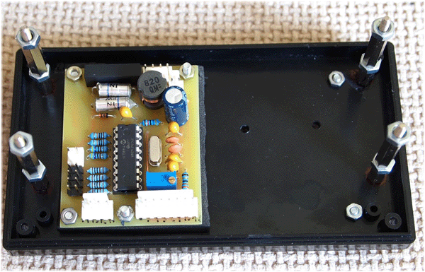
Printed circuit board
Inductance measurement ranges:
10nH - 1000nH
1uH - 1000uH
1mH - 100mH
Capacitance measurement ranges:
0.1pF - 1000pF
1nF - 900nF
A big plus of the device is automatic calibration at power-up, so the calibration error is eliminated, which is inherent in some similar circuits of inductometers, especially analog ones. If necessary, you can re-calibrate at any time by pressing the reset button.
Instrument components
Too precise components are optional, with the exception of one (or more) capacitors, which are used to calibrate the meter. The two 1000pF capacitors on the input should be of good enough quality. Styrofoam is more preferred. Avoid ceramic capacitors, as some of them can have high losses.
Two 10 uF capacitors in the generator should be tantalum (they have low ESR series resistance and inductance). A 4 MHz crystal should be strictly 4,000 MHz, not anything close to that. Every 1% error in the frequency of the crystal adds 2% error to the measurement of the inductance value. The relay should provide about 30 mA of tripping current. Resistor R5 sets the contrast of the LCD display of the LC meter. The device is powered by a conventional Krona battery, since the voltage is further stabilized by the 7805 microcircuit.
Here is another sample of laboratory equipment - LC meter. This measurement mode, especially the L measurement, is almost impossible to find in cheap factory multimeters.
Diagram of this LC meter on the microcontroller was taken from www.sites.google.com/site/vk3bhr/home/index2-html. The device is based on a 16F628A PIC microcontroller, and since I recently purchased a PIC programmer, I decided to test it with this project.
I removed the 7805 regulator because I decided to use a 5 volt cell phone charger.
The circuit has a 5 kΩ trimmer resistor, but in fact I put 10 kΩ, according to the datasheet for the purchased LCD module.
All three capacitors are 10uF tantalum. It should be noted that the capacitor C7 - 100uF is actually 1000uF.
Two 1000pF styroflex capacitors with 1% tolerance, 82uH inductive coil.
The total current consumption with backlight is about 30mA.
Resistor R11 limits the backlight current and must be sized according to the LCD module actually used.
I used the original PCB drawing as a starting point and modified it to match the components I have.
Here is the result:


 The last two photos show the LC meter in action. On the first of them, the measurement of the capacitance of a 1nF capacitor with a deviation of 1%, and on the second, the inductance of 22 μH with a deviation of 10%. The device is very sensitive - that is, with an unconnected capacitor, it shows a capacitance of the order of 3-5 pF, but this is eliminated by calibration.
A circuit for measuring the capacitance of capacitors and the inductance of coils is considered, which is made on only five transistors and, despite its simplicity and accessibility, makes it possible to determine the capacitance and inductance of coils with acceptable accuracy in a wide range. There are four subranges for capacitors and as many as five subranges for coils. After a fairly simple calibration procedure, using two tuning resistors, the maximum error will be about 3%, which, you see, is not bad at all for an amateur radio homemade product.

I propose to solder this simple LC meter circuit with your own hands. The basis of amateur radio homemade products is a generator made on VT1, VT2 and radio components of the harness. Its operating frequency is determined by the LC parameters of the oscillatory circuit, which consists of an unknown capacitance Cx and a coil L1 connected in parallel, in the mode of determining the unknown capacitance - the contacts X1 and X2 must be closed, and in the mode of measuring the inductance Lx, it is connected in series with the coil L1 and capacitor C1 connected in parallel.

With an unknown element connected to the LC-meter, the generator starts working at some frequency, which is fixed by a very simple frequency meter assembled on transistors VT3 and VT4. Then the frequency value is converted into direct current, which deflects the microammeter needle.
Inductance meter circuit assembly. Connecting wires are recommended to be as short as possible to connect unknown elements. After the end of the general assembly process, it is necessary to calibrate the structure in all ranges.
Calibration is carried out by selecting the resistances of the tuning resistors R12 and R15 when connected to the measuring terminals of radio elements with known values. Since in one range the value of the tuning resistors will be the same, and in the other it will be different, it is necessary to determine something average for all ranges, while the measurement error should not go beyond 3%.
This fairly accurate LC meter is assembled on a PIC16F628A microcontroller. The design of the LC meter is based on a frequency meter with an LC oscillator, the frequency of which changes depending on the measured values of inductance or capacitance, and as a result is calculated. The frequency accuracy is up to 1 Hz.

Relay RL1 is required to select L or C measurement mode. The counter works on the basis of mathematical equations. For both unknowns L And C, Equations 1 and 2 are general.

Calibration
When the power is turned on, the instrument automatically calibrates. The initial operating mode is inductance. Wait a couple of minutes for the device circuits to warm up, then press the "zero" toggle switch to recalibrate. The display should show the values ind = 0.00. Now connect a test inductor value, such as 10uH or 100uH. The LC meter should display the exact value on the screen. There are jumpers to configure the counter. Jp1 ~ Jp4.

The inductance meter design below is very simple to repeat and consists of a minimum of radio components. Inductance measuring ranges: - 10nG - 1000nG; 1mcg - 1000mcg; 1mg - 100mg. Capacitance measurement ranges:- 0.1pF - 1000pF - 1nF - 900nF

The measuring device supports auto-calibration at power-on, which eliminates the possibility of human error during manual calibration. Absolutely, at any time you can re-calibrate the meter by simply pressing the reset button. The device has an automatic selection of the measurement range.
There is no need to use any precision and expensive radio components in the design of the device. The only thing is that you need to have one "external" capacity, the value of which is known with great accuracy. Two 1000 pF capacitors should be of normal quality, preferably polystyrene, and two 10 microfarad capacitances should be tantalum.

Quartz must be taken exactly at 4.000 MHz. Every 1% frequency mismatch will result in a 2% measurement error. Relay with low coil current, as the microcontroller is not able to provide a current higher than 30 mA. Do not forget to put a diode in parallel with the relay coil to suppress reverse current and eliminate chatter.
Printed circuit board and microcontroller firmware at the link above.
- 08.10.2014
The stereo volume, balance and tone control on the ТСА5550 has the following parameters: Low harmonic distortion no more than 0.1% Supply voltage 10-16V (12V nominal) Current consumption 15 ... 30mA Input voltage 0.5V (gain at a supply voltage of 12V unit) Tone control range -14…+14dB Balance adjustment range 3dB Difference between channels 45dB Signal to noise ratio …
- 29.09.2014
The schematic diagram of the transmitter is shown in Fig.1. The transmitter (27MHz) delivers about 0.5W of power. A wire 1 m long is used as an antenna. The transmitter consists of 3 stages - master oscillator (VT1), power amplifier (VT2) and manipulator (VT3). The frequency of the master oscillator is given by sq. resonator Q1 at a frequency of 27 MHz. The generator is loaded on the circuit ...
- 28.09.2014
Amplifier parameters: Total range of reproducible frequencies 12 ... 20000Hz Maximum output power of MF-HF channels (Rн=2.7Ω, Up=14V) 2*12W Maximum output power of LF channel (Rн=4Ω, Up=14V) 24W RF channels with SOI 0.2% 2 * 8W Rated power of the low-frequency channel with SOI 0.2% 14W Maximum current consumption 8 A In this circuit, A1 is an RF-MF amplifier, and ...
- 30.09.2014
The VHF receiver operates in the range of 64-108 MHz. The receiver circuit is based on 2 microcircuits: K174XA34 and VA5386, in addition there are 17 capacitors and only 2 resistors in the circuit. The oscillatory circuit is one, heterodyne. On A1, a superheterodyne VHF-FM was performed without ULF. The signal from the antenna is fed through C1 to the input of the IF chip A1 (output 12). The station is tuned in...


