DIY 12 volt output. DIY power supply
Somehow recently I came across a circuit on the Internet for a very simple power supply with the ability to adjust the voltage. The voltage could be adjusted from 1 Volt to 36 Volt, depending on the output voltage on the secondary winding of the transformer.
Take a close look at the LM317T in the circuit itself! The third leg (3) of the microcircuit is connected to capacitor C1, that is, the third leg is INPUT, and the second leg (2) is connected to capacitor C2 and a 200 Ohm resistor and is an OUTPUT.
Using a transformer, from a mains voltage of 220 Volts we get 25 Volts, no more. Less is possible, no more. Then we straighten the whole thing with a diode bridge and smooth out the ripples using capacitor C1. All this is described in detail in the article on how to obtain constant voltage from alternating voltage. And here is our most important trump card in the power supply - this is a highly stable voltage regulator chip LM317T. At the time of writing, the price of this chip was around 14 rubles. Even cheaper than a loaf of white bread.
Description of the chip
LM317T is a voltage regulator. If the transformer produces up to 27-28 volts on the secondary winding, then we can easily regulate the voltage from 1.2 to 37 volts, but I would not raise the bar to more than 25 volts at the transformer output.
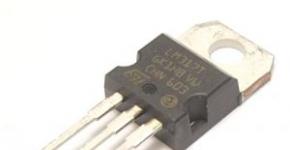
The microcircuit can be executed in the TO-220 package:

or in D2 Pack housing

It can pass a maximum current of 1.5 Amps, which is enough to power your electronic gadgets without voltage drop. That is, we can output a voltage of 36 Volts with a current load of up to 1.5 Amps, and at the same time our microcircuit will still output 36 Volts - this, of course, is ideal. In reality, fractions of volts will drop, which is not very critical. With a large current in the load, it is more advisable to install this microcircuit on a radiator.
In order to assemble the circuit, we also need a variable resistor of 6.8 Kilo-Ohms, or even 10 Kilo-Ohms, as well as a constant resistor of 200 Ohms, preferably from 1 Watt. Well, we put a 100 µF capacitor at the output. Absolutely simple scheme!
Assembly in hardware
Previously, I had a very bad power supply with transistors. I thought, why not remake it? Here is the result ;-)

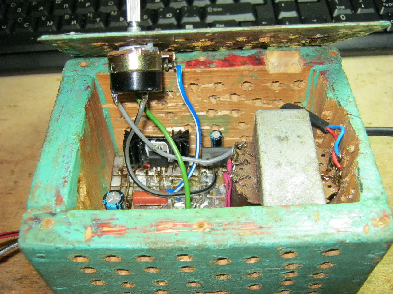
Here we see the imported GBU606 diode bridge. It is designed for a current of up to 6 Amps, which is more than enough for our power supply, since it will deliver a maximum of 1.5 Amps to the load. I installed the LM on the radiator using KPT-8 paste to improve heat transfer. Well, everything else, I think, is familiar to you.

And here is an antediluvian transformer that gives me a voltage of 12 volts on the secondary winding.

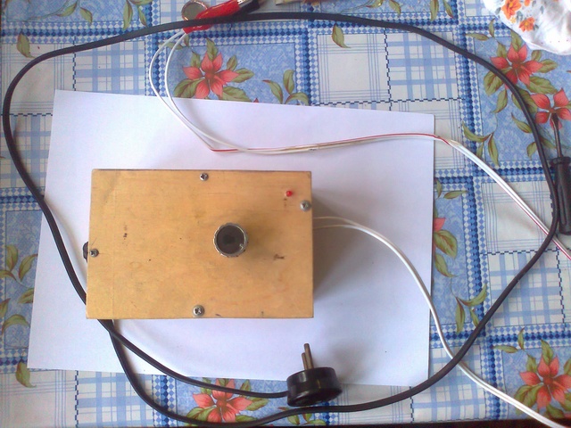
We carefully pack all this into the case and remove the wires.
So what do you think? ;-)

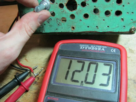
The minimum voltage I got was 1.25 Volts, and the maximum was 15 Volts.


I set any voltage, in this case the most common are 12 Volts and 5 Volts

Everything works great!
This power supply is very convenient for adjusting the speed of a mini drill, which is used for drilling circuit boards.

Analogues on Aliexpress
By the way, on Ali you can immediately find a ready-made set of this block without a transformer.

Too lazy to collect? You can buy a ready-made 5 Amp for less than $2:

You can view it at this link.
If 5 Amps is not enough, then you can look at 8 Amps. It will be enough for even the most seasoned electronics engineer:

At 1-2 amperes, but it is already problematic to obtain a higher current. Here we will describe a high-power power supply with a standard voltage of 13.8 (12) volts. The circuit is 10 amperes, but this value can be increased further. There is nothing special in the circuit of the proposed power supply, except that, as tests have shown, it is capable of delivering a current of up to 20 Amps for a short time or 10A continuously. To further increase power, use a larger transformer, diode bridge rectifier, higher capacitor capacity and number of transistors. For convenience, the power supply circuit is shown in several figures. The transistors do not have to be exactly the ones in the circuit. We used 2N3771 (50V, 20A, 200W) because there are many of them in stock.


The voltage regulator operates within small limits, from 11 V to 13.8 at full load. With an open circuit voltage value of 13.8V (nominal battery voltage is 12V), the output will drop to 13.5 for about 1.5A, and 12.8V for about 13A.

The output transistors are connected in parallel, with 0.1 ohm 5 watt wirewound resistors in the emitter circuits. The more transistors you use, the higher the peak current that can be drawn from the circuit.

The LEDs will show incorrect polarity, and the relay will block the power supply stabilizer from the rectifiers. High power thyristor BT152-400 opens when overvoltage occurs and takes on the current, causing the fuse to blow. Don't think that the triac will burn out first, the BT152-400R can withstand up to 200A for 10ms. This power source can also serve as a charger for car batteries, but to avoid incidents, no need to leave the battery connected for a long time unattended.

Those beginners who are just starting to study electronics are in a hurry to build something supernatural, like microbugs for wiretapping, a laser cutter from a DVD drive, and so on... and so on... What about assembling a power supply with an adjustable output voltage? This power supply is an essential item in every electronics enthusiast's workshop.
Where to start assembling the power supply?
First, you need to decide on the required characteristics that the future power supply will satisfy. The main parameters of the power supply are the maximum current ( Imax), which it can supply to the load (powered device) and the output voltage ( U out), which will be at the output of the power supply. It’s also worth deciding what kind of power supply we need: adjustable or unregulated.
Adjustable power supply is a power supply whose output voltage can be changed, for example, from 3 to 12 volts. If we need 5 volts - we turned the regulator knob - we got 5 volts at the output, we need 3 volts - we turned it again - we got 3 volts at the output.
An unregulated power supply is a power supply with a fixed output voltage - it cannot be changed. For example, the well-known and widely used “Electronics” power supply D2-27 is unregulated and has an output voltage of 12 volts. Also unregulated power supplies are all kinds of chargers for cell phones, adapters for modems and routers. All of them, as a rule, are designed for one output voltage: 5, 9, 10 or 12 volts.
It is clear that for a novice radio amateur it is the regulated power supply that is of greatest interest. It can power a huge number of both homemade and industrial devices designed for different supply voltages.
Next you need to decide on the power supply circuit. The circuit should be simple, easy to repeat by beginning radio amateurs. Here it is better to stick to a circuit with a conventional power transformer. Why? Because finding a suitable transformer is quite easy both in radio markets and in old consumer electronics. Making a switching power supply is more difficult. For a switching power supply, it is necessary to produce quite a lot of winding parts, such as a high-frequency transformer, filter chokes, etc. Also, switching power supplies contain more electronic components than conventional power supplies with a power transformer.
So, the circuit of the regulated power supply proposed for repetition is shown in the picture (click to enlarge).

Power supply parameters:
Output voltage ( U out) – from 3.3...9 V;
Maximum load current ( Imax) – 0.5 A;
The maximum amplitude of output voltage ripple is 30 mV;
Overcurrent protection;
Protection against overvoltage at the output;
High efficiency.
It is possible to modify the power supply to increase the output voltage.
The circuit diagram of the power supply consists of three parts: a transformer, a rectifier and a stabilizer.
Transformer. Transformer T1 reduces the alternating mains voltage (220-250 volts), which is supplied to the primary winding of the transformer (I), to a voltage of 12-20 volts, which is removed from the secondary winding of the transformer (II). Also, “part-time”, the transformer serves as a galvanic isolation between the electrical network and the powered device. This is a very important function. If the transformer suddenly fails for any reason (voltage surge, etc.), then the mains voltage will not be able to reach the secondary winding and, therefore, the powered device. As you know, the primary and secondary windings of a transformer are reliably isolated from each other. This circumstance reduces the risk of electric shock.
Rectifier. From the secondary winding of power transformer T1, a reduced alternating voltage of 12-20 volts is supplied to the rectifier. This is already a classic. The rectifier consists of a diode bridge VD1, which rectifies alternating voltage from the secondary winding of the transformer (II). To smooth out voltage ripples, after the rectifier bridge there is an electrolytic capacitor C3 with a capacity of 2200 microfarads.
Adjustable pulse stabilizer.
The pulse stabilizer circuit is assembled on a fairly well-known and affordable DC/DC converter microcircuit - MC34063.
To make it clear. The MC34063 chip is a specialized PWM controller designed for pulsed DC/DC converters. This chip is the core of the adjustable switching regulator used in this power supply.
The MC34063 chip is equipped with a protection unit against overload and short circuit in the load circuit. The output transistor built into the microcircuit is capable of delivering up to 1.5 amperes of current to the load. Based on a specialized microcircuit, the MC34063 can be assembled as step-up ( Step-Up), and downward ( Step-Down) DC/DC converters. It is also possible to build adjustable pulse stabilizers.
Features of pulse stabilizers.
By the way, switching stabilizers have a higher efficiency compared to stabilizers based on KR142EN series microcircuits ( CRANKS), LM78xx, LM317, etc. And although power supplies based on these chips are very simple to assemble, they are less economical and require the installation of a cooling radiator.
The MC34063 chip does not require a cooling radiator. It is worth noting that this chip can often be found in devices that operate autonomously or use backup power. The use of a switching stabilizer increases the efficiency of the device, and, consequently, reduces power consumption from the battery or battery. Due to this, the autonomous operating time of the device from a backup power source increases.
I think it’s now clear why a pulse stabilizer is good.
Parts and electronic components.
Now a little about the parts that will be required to assemble the power supply.

Power transformers TS-10-3M1 and TP114-163M
A TS-10-3M1 transformer with an output voltage of about 15 volts is also suitable. You can find a suitable transformer in radio parts stores and radio markets, the main thing is that it meets the specified parameters.
Chip MC34063 . The MC34063 is available in DIP-8 (PDIP-8) for conventional through-hole mount and SO-8 (SOIC-8) for surface mount. Naturally, in the SOIC-8 package the chip is smaller in size, and the distance between the pins is about 1.27 mm. Therefore, it is more difficult to make a printed circuit board for a microcircuit in the SOIC-8 package, especially for those who have only recently begun to master printed circuit board manufacturing technology. Therefore, it is better to take the MC34063 chip in a DIP package, which is larger in size, and the distance between the pins in such a package is 2.5 mm. It will be easier to make a printed circuit board for a DIP-8 package.
Chokes. Chokes L1 and L2 can be made independently. To do this, you will need two ring magnetic cores made of 2000HM ferrite, size K17.5 x 8.2 x 5 mm. The standard size is deciphered as follows: 17.5 mm. – outer diameter of the ring; 8.2 mm. - inner diameter; a 5 mm. – height of the ring magnetic circuit. To wind the choke you will need a PEV-2 wire with a cross section of 0.56 mm. 40 turns of such wire must be wound on each ring. The turns of the wire should be distributed evenly over the ferrite ring. Before winding, the ferrite rings must be wrapped in varnished cloth. If you don’t have varnished fabric at hand, you can wrap the ring with three layers of tape. It is worth remembering that ferrite rings may already be painted - covered with a layer of paint. In this case, there is no need to wrap the rings with varnished cloth.
In addition to homemade chokes, you can also use ready-made ones. In this case, the process of assembling the power supply will speed up. For example, as chokes L1, L2 you can use the following surface-mount inductors (SMD - inductor).

As you can see, on the top of their case the inductance value is indicated - 331, which stands for 330 microhenry (330 μH). Also, ready-made chokes with radial leads for conventional installation in holes are suitable as L1, L2. This is what they look like.

The amount of inductance on them is marked either with a color code or with a number. For the power supply, inductances marked 331 (i.e. 330 μH) are suitable. Taking into account the tolerance of ±20%, which is allowed for elements of household electrical equipment, chokes with an inductance of 264 - 396 μH are also suitable. Any inductor or inductor is designed for a certain direct current. As a rule, its maximum value ( I DC max) is indicated in the datasheet for the throttle itself. But this value is not indicated on the body itself. In this case, you can approximately determine the value of the maximum permissible current through the inductor based on the cross-section of the wire with which it is wound. As already mentioned, to independently manufacture chokes L1, L2, you need a wire with a cross-section of 0.56 mm.
Throttle L3 is homemade. To make it, you need a magnetic core made of ferrite. 400HH or 600HH with a diameter of 10 mm. You can find this in antique radios. There it is used as a magnetic antenna. You need to break off a piece 11 mm long from the magnetic circuit. This is quite easy to do; ferrite breaks easily. You can simply tightly clamp the required section with pliers and break off the excess magnetic circuit. You can also clamp the magnetic core in a vice, and then sharply hit the magnetic core. If you fail to carefully break the magnetic circuit the first time, you can repeat the operation.
Then the resulting piece of magnetic circuit must be wrapped with a layer of paper tape or varnished cloth. Next, we wind 6 turns of PEV-2 wire folded in half with a cross-section of 0.56 mm onto the magnetic circuit. To prevent the wire from unwinding, wrap it with tape on top. Those wire leads from which winding of the inductor began are subsequently soldered into the circuit in the place where the points are shown in image L3. These points indicate the beginning of winding the coils with wire.
Additions.
Depending on your needs, you can make certain changes to the design.
For example, instead of a VD3 zener diode type 1N5348 (stabilization voltage - 11 volts), you can install a protective diode - a suppressor - in the circuit 1.5KE10CA.

A suppressor is a powerful protective diode, its functions are similar to a zener diode, however, its main role in electronic circuits is protective. The purpose of the suppressor is to suppress high-voltage pulse noise. The suppressor has a high speed and is able to extinguish powerful impulses.
Unlike the 1N5348 zener diode, the 1.5KE10CA suppressor has a high response speed, which will undoubtedly affect the performance of the protection.
In technical literature and among radio amateurs, a suppressor can be called differently: protective diode, limiting zener diode, TVS diode, voltage limiter, limiting diode. Suppressors can often be found in switching power supplies - there they serve as protection against overvoltage of the powered circuit in the event of faults in the switching power supply.
You can learn about the purpose and parameters of protective diodes from the article about suppressor.
Suppressor 1.5KE10 C A has a letter WITH in the name and is bidirectional - the polarity of its installation in the circuit does not matter.
If there is a need for a power supply with a fixed output voltage, then the variable resistor R2 is not installed, but replaced with a wire jumper. The required output voltage is selected using a constant resistor R3. Its resistance is calculated using the formula:
Uout = 1.25 * (1+R4/R3)
After the transformations, we obtain a formula that is more convenient for calculations:
R3 = (1.25 * R4)/(U out – 1.25)
If you use this formula, then for U out = 12 volts you will need a resistor R3 with a resistance of about 0.42 kOhm (420 Ohm). When calculating, the value of R4 is taken in kilo-ohms (3.6 kOhm). The result for resistor R3 is also obtained in kilo-ohms.
To more accurately set the output voltage U out, you can install a trimming resistor instead of R2 and set the required voltage using the voltmeter more accurately.
It should be taken into account that a zener diode or suppressor should be installed with a stabilization voltage 1...2 volts higher than the calculated output voltage ( U out) power supply. So, for a power supply with a maximum output voltage equal to, for example, 5 volts, a 1.5KE suppressor should be installed 6V8 CA or similar.
Manufacturing of printed circuit board.
A printed circuit board for a power supply can be made in different ways. Two methods for making printed circuit boards at home have already been discussed on the pages of the site.
The fastest and most comfortable way is to make a printed circuit board using a printed circuit board marker. Marker used Edding 792. He showed himself at his best. By the way, the signet for this power supply was made with just this marker.
The second method is suitable for those who have a lot of patience and a steady hand. This is a technology for making a printed circuit board using a correction pencil. This is a fairly simple and affordable technology that will be useful to those who could not find a marker for printed circuit boards, but do not know how to make boards with LUT or do not have a suitable printer.
The third method is similar to the second, only it uses tsaponlak - How to make a printed circuit board using tsaponlak?
In general, there is plenty to choose from.
Setting up and checking the power supply.
To check the functionality of the power supply, you first need to turn it on, of course. If there are no sparks, smoke or pops (this is quite possible), then the power supply is most likely working. At first, keep some distance from him. If you made a mistake when installing electrolytic capacitors or set them to a lower operating voltage, they can “pop” and explode. This is accompanied by electrolyte splashing in all directions through the protective valve on the body. So take your time. You can read more about electrolytic capacitors. Don’t be lazy to read this – it will come in handy more than once.
Attention! The power transformer is under high voltage during operation! Don't put your fingers near it! Don't forget about safety rules. If you need to change something in the circuit, then first completely disconnect the power supply from the mains, and then do it. There is no other way - be careful!
At the end of this whole story, I want to show you a finished power supply that I made with my own hands.

Yes, it does not yet have a housing, a voltmeter and other “goodies” that make it easier to work with such a device. But, despite this, it works and has already managed to burn out an awesome three-color flashing LED because of its stupid owner, who loves to twist the voltage regulator recklessly. I wish you, novice radio amateurs, to collect something similar!
A 12 Volt power supply will allow you to power almost any household appliance, including even a laptop. Please note that the laptop input is supplied with voltage up to 19 Volts. But it will work great if powered from 12. However, the maximum current is 10 Amperes. Only consumption reaches this value very rarely, the average remains at the level of 2-4 Amperes. The only thing you should take into account is that when replacing a standard one with a homemade one, you will not be able to use the built-in battery. But still, a 12-volt power supply is ideal even for such a device.
Power supply parameters
The most important parameters of any power supply are the output voltage and current. Their values depend on one thing - the wire used in the secondary winding of the transformer. How to select it will be discussed below. For yourself, you must decide in advance for what purposes you plan to use the 12 Volt power supply. If you need to power low-power equipment - navigators, LEDs, etc., then an output of 2-3 Amps is quite sufficient. And then there will be a lot of this.
But if you plan to use it to carry out more serious actions - for example, charging a car, then you will need 6-8 Amperes at the output. The charging current must be ten times less than the battery capacity - this requirement must be taken into account. If there is a need to connect devices whose supply voltage differs significantly from 12 Volts, then it is wiser to set the adjustment.
How to choose a transformer

The first element is a voltage converter. The transformer helps convert an alternating voltage of 220 Volts into the same amplitude, only with a much smaller value. At the very least you need a smaller value. For powerful power supplies, you can take a transformer like TS-270 as a basis. It has high power, there are even 4 windings that produce 6.3 Volts each. They were used to power incandescent radio tubes. Without much difficulty, you can make a 12 Volt 12 Ampere power supply out of it, which can even charge a car battery.
But if you are not completely satisfied with its windings, then you can remove all the secondary ones and leave only the network one. And wind the wire. The problem is how to calculate the required number of turns. To do this, you can use a simple calculation scheme - count how many turns the secondary winding contains, which produces 6.3 Volts. Now just divide 6.3 by the number of turns. And you will get the amount of voltage that can be removed from one turn of wire. All that remains is to calculate how many turns need to be wound in order to get 12.5-13 Volts at the output. It will be even better if the output voltage is 1-2 Volts higher than required.
Making a rectifier

What is a rectifier and what is it for? This is a semiconductor diode device that is a converter. With its help it turns into a permanent one. To analyze the operation of the rectifier stage, it is more clear to use an oscilloscope. If you see a sine wave in front of the diodes, then after them there will be an almost flat line. But small pieces of the sinusoid will still remain. Get rid of them later.
The choice of diodes should be taken with the utmost seriousness. If a 12-volt power supply is used as a battery charger, then you will need to use elements with a reverse current of up to 10 Amps. If you intend to supply power to low-current consumers, then a bridge assembly will be quite sufficient. This is where it's worth stopping. Preference should be given to a rectifier circuit assembled as a bridge - consisting of four diodes. If used on one semiconductor (half-wave circuit), then the efficiency of the power supply is almost halved.
Filter block

Now that the output has a constant voltage, it is necessary that the 12 Volt power supply be slightly improved. For this purpose you need to use filters. To power household appliances, it is enough to use an LC circuit. It is worth talking about it in more detail. An inductance - a choke - is connected to the positive output of the rectifier stage. Current must pass through it; this is the first stage of filtration. Next comes the second - an electrolytic capacitor with a large capacity (several thousand microfarads).
After the choke, an electrolytic capacitor is connected to the positive. Its second pin is connected to the common wire (minus). The essence of the operation of an electrolytic capacitor is that it allows you to get rid of the entire alternating component of the current. Remember when there were small pieces of sine wave left at the output of the rectifier? This is exactly what you need to get rid of, otherwise the 12 Volt 12 Ampere power supply will interfere with the device connected to it. For example, a cassette player or radio will produce a strong hum.
Output voltage stabilization
To stabilize the output voltage, you can use just one semiconductor element. This can be either a zener diode with an operating voltage of 12 Volts, or more modern and advanced assemblies such as LM317, LM7812. The latter are designed to stabilize the voltage at 12 Volts. Consequently, even if the output of the rectifier stage is 15 Volts, after stabilization only 12 will remain. Everything else goes into heat. This means that it is extremely important to install a stabilizer on the radiator.
Voltage adjustment 0-12 Volts

For greater versatility of the device, you should use a simple circuit that can be built in a few minutes. This can be achieved using the previously mentioned LM317 assembly. Only the difference from the switching scheme in stabilization mode will be small. 5 kOhm is connected to the break in the wire that goes to minus. A resistance of about 220 Ohms is connected between the output of the assembly and the variable resistor. And between the input and output of the stabilizer, protection against reverse voltage is a semiconductor diode. Thus, a 12 Volt power supply, assembled with your own hands, turns into a multifunctional device. Now all that remains is to assemble it and calibrate the scale. Or you can even install an electronic voltmeter at the output, which can be used to view the current voltage value.
Hello to all radio amateurs, in this article I would like to introduce you to a power supply with voltage regulation from 0 to 12 volts. It is very easy to set the desired voltage, even in millivolts. The diagram does not contain any purchased parts - all this can be pulled out of old equipment, both imported and Soviet.
Schematic diagram of power supply unit (reduced)
The case is made of wood, in the middle there is a 12 volt transformer, a 1000 uF x 25 volt capacitor and a board that regulates the voltage.

Capacitor C2 must be taken with a large capacity, for example, to connect an amplifier to the power supply and so that the voltage does not drop at low frequencies.

It is better to install transistor VT2 on a small radiator. Because during prolonged operation it can heat up and burn out; I already burned out 2 of them until I installed a decent-sized radiator.

Resistor R1 can be set constant; it does not play a big role. On top of the case there is a variable resistor that regulates the voltage, and a red LED that shows whether there is voltage at the power supply output.
At the output of the device, in order not to constantly screw the wires to something, I soldered alligator clips - they are very convenient. The circuit does not require any settings and works reliably and stably; any radio amateur can really do it. Thank you for your attention, good luck everyone! .