Self-made electronic water dialers. Scheme of automatic maintenance of the water level
Hi all. Today we will talk about a very simple kit for self-assembly of the device, to control the water level. This set can be successfully unsoldered by a 5-7 grade student in one evening. Of course, you can do it completely on your own, including the fee, but I decided to save time, so I ordered a set.
The set was purchased with the aim of at least somehow automating the collection of water in a barrel in the country. Moreover, this is not quite a barrel, but rather a pipe going down 2.5-3 meters, so there are decent water reserves there (for simplicity, let it be a barrel). The idea was simple, as long as there is no regular water supply, the electrovalve opens and draws water into the barrel at a given level. Water consumption by buckets as needed and automatic topping up into the barrel. In order for the valve to often not work from water fluctuations, several levels are conceived. The lower one at which the valve turns on and the upper one at which it turns off. Those. there is a certain dead zone in which there is a flow of water, but there is no water supply to the barrel yet. By the way, this dead zone is actually such a thing as hysteresis.
Last year, this function was performed by such a sorry device as a float mechanism from the toilet bowl. It worked properly, occasionally clogged, because the water comes through pipes straight from the river. But in the end, it did not survive the winter, because it was made of plastic and fell apart from frost.
This set was designed to replace the failed mechanism.
While storing the collected board and waiting for the summer season, an attempt was made to apply the collected board in production, on such an installation. 
It's just a big pan with a 27 kW heating element type heater. The products are taken out of the refrigerator in whole pallets and placed in a pan. It is necessary to heat all this up to 90 C. Can you imagine how much electricity is spent daily?!
To estimate the volume, I will attach a couple of photos:


Products, among other things, are pork stomachs and curly (part of the intestines).
As far as I know, the stomachs are stuffed with something and eaten, with the intestines it’s about the same - including sausages with sausages.
This case is boiled and re-frozen. Then he goes to China. So, the cycle of goods in nature. We give them natural by-products, and in response, electronics ...
There was a question to transfer the heating of the pan to steam. So more economical and more powerful. Productivity grows exponentially. This is where a level sensor was required so that no one would be scalded by steam and steam was supplied only when there was at least a minimum amount of water in the tank.
However, I caught myself in time and refused the final installation, although the tests showed the board to work. It is contraindicated to use in the production of homemade products. Therefore, we found a less quickly needed device that performs the same functions, but also has a certificate. The principle of operation of a factory device practically corresponds to a set from an online store and, in a particular case, performs the same functions.
This device is of domestic production Aries SAU-M7. 
Delivery and packaging:
Banggood is very stable, small package and several layers of polyethylene foam. 

In a small bag there is a "bunch" of parts, a board and wires.

I didn’t sort by denominations, I just laid them out for clarity.

The scheme is not simple, but very simple. 4 elements 2I-NOT are used, and two of them perform the function of a trigger. It is needed to form a hysteresis loop.
Pins 1 and 2 of J3 provide a low level signal and turn on the relay. Contacts J4 1 and 2 - high level and emergency, when any of them is triggered, the relay turns off. The operation of the relay is duplicated by the ignition of the LED. The circuit works confidently on tap water and just as confidently on water after water treatment, in which there are fewer salts.
I assembled the board almost without looking at the circuit, except that I looked at the value of the resistors.
It is unlikely to confuse the conclusions and even install details such as connectors or transistors incorrectly prevent the applied silk-screen printing.
The only negative during installation - I mixed up the LEDs. But this is so, the little things do not affect performance.

Self-made level sensors of the conductometric type were used as sensors. This is how they look like assembled:

On the board from the installation side of the parts, silk-screen printing is applied, quite high quality. 
The process of desoldering parts will not be of interest to you, since I am not an assembler and do not own the features of those process for assembling boards. What came into his hand from the edge, then soldered.
The printed circuit board on the soldering side is covered with a protective mask. There is no metallization. The payment is one-sided.

I used solder type POS 61 with rosin. Screwed up a little. 
I fixed the power wires with sealant so that they would not break off at the exit from the holes. The wires that came with the kit seemed to me too short. 
I washed the board with a solvent and alcohol and covered it with a layer of Plastik 70. I immediately noticed the difference between my previous boards and this one. The surface is shiny and the contacts are covered with a layer of film.
There was some inconvenience, which is actually a plus. I wanted to make a video about the operation of the board using a multimeter, but I got a problem in the form of the fact that the probes do not tritely push through the protective coating. Therefore, there is no multimeter in the video. 
Video demonstration of the board:
Update: while writing a review, I didn’t even pay attention to the product page, as usual. And only after writing a review did I pay attention to the product. The fee does not match the one that was sent to me and, judging by the comments, many are sent two different versions of the fee. This does not affect functionality. Both boards are functional.
Results: The simplest set, available for schoolchildren, also has a practical application. I recommend to buy. The sediment remained small due to the fact that the board came not the one in the description.
In my case, the wires turned out to be superfluous. They were probably planned to output LEDs from the board to the front panel and connect the power supply.
I plan to buy +52 Add to favorites Liked the review +25 +47To ensure convenient control of the operation of pumps, there are a large number of different devices, among which the float is widely used. Among the features of this device, it should be noted that it can simultaneously perform the function of a water level sensor and at the same time an actuator for controlling the pump. The place of their placement is storage tanks, reservoirs, tanks, as well as wells, etc.
The space of one such tank is enough to accommodate several floats, and they can solve various problems:
- Monitor the operation of the main pump;
- Ensure the efficient operation of the auxiliary pump;
- Act as an emergency level sensor;
- Used as overflow sensor.
With the help of similar water level control devices that are used in these systems, it is possible to protect the pump unit from going dry. Also, in the case of filling different tanks, this element allows you to protect them from overflow.
Can be distinguished several types of floats for pumps:
- lungs;
- heavy.
The former have become widespread in water supply and sanitation systems. The latter are mostly used as part of drainage, fecal and rainwater runoff. In stores, these devices are offered with a cable length of 2, 3, 5 and 10 meters.
Device and design
An element such as a float switch for controlling the water level has floating plastic body. It contains an electrical switch and a lever that allows you to move the switch contacts. Also included is a steel ball, which, in the event of a change in the position of the float, corrects the position of the lever itself. A cable is connected to the switch, consisting of three wires: the first is common, and the rest are connected to the normally closed and normally open contact of the switch.
Closing the circuit provide black and blue wires at the moment when the heat is in the down position. If it is moved to the upper position, black and brown wires will already act as normally open contacts. A prerequisite here is the insulation of the wire that does not provide connection to the device. It is important to make sure that the supply cable has moisture-proof properties, while the design of the plastic box must be airtight. To seal the cable outlet, a mechanical seal is used, and it also has a special device that allows you to remove mechanical stresses in the cable.
Inside the insulated cavity of the cable entry is polymer resin which protects against water ingress. It is with the chemical properties and heat resistance of the body and cable sheath, which are made using thermoplastic rubber, that the ability of the float switch to perfectly tolerate interaction with alcohols, uric acid, fecal water, gasoline and other aggressive substances is associated.
Due to the absence of pores on the surface of plastic housings, pollution does not appear on it. At the same time, this feature ensures that sand, paper and other solids slide off, while the float switch retains its floating properties.
Sensor specifications for water level control:
- Mains voltage, V - 220 ± 10%;
- Maximum switched current, A:
- 8A - for reactive load (pumps, fans, compressors, etc.);
- 10A - for active load (starters, switches, heating elements, lamps, etc.);
- Operating temperature range: 0-60°C;
- Protection: IP 68.
Advantages
 Among all the advantages that a float switch has for controlling the water level, first of all, it should be highlighted that it is capable of act as a normal sensor to determine the water level in tanks. Moreover, he successfully performs this task, even despite the fact that for what purposes the capacity is used and what volume it has. At the same time, this water level control device can help make the operation of pumping equipment more convenient. With the help of such a device, the control of the functions of industrial, domestic water supply systems is simplified.
In some cases, it can be used to successfully drain fluid. Also, a float switch for controlling the water level can be part of the equipment for the construction of sewer communications. Ease of operation and the high efficiency of its application and provided the float switch with wide distribution in a wide variety of systems where the task of controlling water arises.
It is worth noting that the ability to provide reliable protection for pumping systems during dry operation is not the only positive qualities of such devices. At the same time, with their help, it is possible to avoid the situation when water overflows in the containers.
Installation
 Float switches can be installed using one of several methods. Even before installing this device, you should make sure that the current rating used to operate the pump is less than the maximum allowable current value, which is given in the technical specifications for this type of float. Among the known methods of mounting a float switch for water level control, the simplest to implement is its placement in the tank, involving the use of a float with a cable and a special sinker that is attached to this device.
With this installation option, the sinker must be fixed on the cable, and then empirically calculate the length of the free-play arm of the float. Using the latch, you need to fix the sinker on the cable. After that, the cable itself must be firmly fixed on the outside of the tank. Next, they are already moving on to connecting the float switch to the pump. After that, the device can be used for its intended purpose.
The option of installing a float for pumps, which involves the use of a supply cable, can only be used in a situation where there is no risk of hooking or hanging the main device in the tank itself and when only one float is placed in it.
In some situations, it may be decided to install several floats at once to control the water level. In this case, their installation is carried out on a special bar. As the latter, fragments of a plastic pipe are most often used, which must be firmly fixed in the tank. After that, floats are installed on the pipe, and they must be correctly set, adjusted and spaced along the length of the rod so that they do not create difficulties for each other for normal operation.
The cables that come from the float switches are connected to the rod using clamps. When choosing the number of float switches, attention should be paid to the number of pumps or the type and number of guards and control panels used. In some situations, the problem of ensuring the reliable operation of float switches can be solved by using several rods.
When determining the installation scheme of float switches, their number and their location, it is necessary to take into account the features of the place of their installation each time or focus on the project.
The principle of operation of the float for pumps
Devices such as float switches can provide for various schemes for their use, and this also affects their principle of operation.
Water supply system, filling and emptying the reservoir tank capacity
 With this scheme of operation, at the moment of ascent, the float de-energizes the pump, which supplies water to the tank. Signal to turn on will come only at the moment it reaches the bottom. This situation occurs only when the container is empty.
The float gives a signal to turn on the automatic water supply station at the moment it is on the surface. Switching off the station can only occur when the float sinks to the bottom with an empty tank.
From the side of the float, a signal was received to close the valve or valve with a servo drive at the moment it was raised to the surface. The opening of the same valve or valve will happen only the moment it sinks to the bottom with an empty tank.
The work of a float can only be in the notification of the control center or the operator at the time of its raising to the surface, which will correspond to the filling of the container. Information about the lack of water will come at the moment when the float reaches the bottom.
sewerage system
The inclusion of a float of fecal pumping equipment will occur only at the moment the main control device is raised up. The pumping unit is switched on when the control device is immersed to the bottom.
One float can simultaneously serve two pumping units: the first unit can supply water to the tank, provided that the float is in the bottom position. At this point, the other pump is idle. When the float is in the upper position, the second pump is turned on, the task of which is to pump water out of the tank. At this time, the pump that supplies water to the tank is inactive. Despite its simplicity, the above scheme for using a float switch is not effective enough, since this does not eliminate the difficulties with regular delivery of water at those moments when the tank is being filled.
Operation, maintenance and repair
 It is possible to ensure long-term operation of floats for pumps only if the rules for their use are not violated. In a situation where the float switch is part of the water supply and sanitation system, you can not waste time and effort on its maintenance. If this device controls the operation of fecal or sewer pits, then it is recommended that at least once a month, perform float cleaning and a dirt pump using a pressurized water jet.
This procedure will avoid sticking or sticking of the float to the pump or pressure pipe. A float switch, which, due to certain circumstances, is not able to perform its main task, is not repairable, therefore, in such situations, it is replaced. This work should be carried out by service center specialists.
Conclusion
In situations where there is a need to ensure the supply of drinking water to the house or the removal of polluted drains, it is necessary to use in combination with pumping equipment and special devices. Among them, the float switch is quite effective. The benefit of its use lies in the fact that it controls the amount of liquid in the tank, and, focusing on this, determines the operating mode of the pumping unit.
Such a device avoids the transition of the pump to the "dry running" mode, which has a positive effect on its service life. In addition to this, a considerable amount of electricity is saved, since the float switch allows the pump to be activated only when necessary.
After installing a new barrel of a larger volume on a summer shower, it became necessary to install some kind of "sensor" of the water level, so as not to constantly climb on the roof of the shower, and besides, the new barrel is equipped with a lid that is fixed with a clamp, and constantly remove it and I don't really want to see how much water is left. Therefore, I installed such an easy-to-make device.
Necessary materials:
Styrofoam (I found such a piece, as in the photo, in a box from a gas stove, they dig up camphor during transportation.);
- small nut
- large nut
- a long screw;
- two pieces of plastic strip;
- fishing line.
Sensor manufacturing
First of all, we drill a through hole in the middle of the foam (this is done so that when we tighten the screw, the foam does not split), as well as on both plates.


Then we fasten the parts as shown in the photo:
View from above:

Bottom view:

We fasten the fishing line to the screw and our “sensor” is almost ready.

Now we carry everything to the roof of the shower, drill a hole in the tank lid (the hole must be made in such a way that the fishing line passes freely through it).


And here is the finished result.


Principle of operation our "sensor" is very simple. When the water in the tank runs out, our float goes down, and the washer on the outside goes up, therefore, you need to add water. And when the water is poured, it is also very convenient to follow. Of course, you can make markings on the tank and hang some kind of arrow instead of a puck, but this is a personal matter for everyone. If you have any questions, please ask!
Thank you for your attention!
In summer cottages and garden plots, various water storage tanks are often used, designed to ensure that the water in them can warm up before watering, and be saturated with oxygen. They are also used in the case when the flow of water is periodic or not guaranteed. For example, a well or well has a very small flow rate (i.e. they give very little water at a “one time” and it takes some time to wait until it is collected again). Or water is supplied through a centralized system at a certain time.
Be that as it may, it is useful to have some kind of device that would automatically replenish the water supply in the water tower or tank, including a booster pump, when the water level in the tank falls below the critical (or set) level.
For those who have a centralized water supply at the site, which is under pressure at the time of water supply, it is extremely easy to make such an automatic machine. It is enough to put plumbing fixtures in the container, such as is in the toilet bowl. Its float shut-off valve will keep the tank full at all times.
You can even get by with a simple tap with a handle. A small lever (stick) is tied to the handle, and 1-2 plastic bottles are attached to its end. The tap is securely fastened in such a way that when the tank is completely filled, it is closed and the PET bottles are slightly submerged. If there is a flow of water, then the floats - the bottles will begin to fall down and open the tap a little. If there is water in the system, it will begin to flow into the tank. If there is no water in the system, then the tap will be open until water appears and fills the tank.
It is much more difficult to organize automatic pumping for those who do not have running water, and water is pumped from a well or well. Here you need some kind of machine that includes a pump. There are many such developments. Starting from float switches, ending with electronic water level sensors. Branded float switch - quite expensive and rarely sold separately. You can make it yourself (see the article "Homemade float switch"), and this is within the power of fairly handy craftsmen. Yes, and it must be done very carefully - all the same, a full guarantee of sealing the wires in the water is necessary. Electronic devices - generally "too tough" - units. And yes, it won't be cheap.
Summer residents, on the other hand, need the simplest device that anyone can assemble, what they say “from a tin can”, and with the cost of a bottle of beer. Such devices must meet two basic requirements. First - They should not have a so-called. "bounce" of contacts. And there should be two stable positions - “on” and “off”. This is called the "tumbler effect". Otherwise, with a smooth supply of the closing contact to others, a breakdown of the microscopic air gap, sparking, and burning of the contacts is inevitable. It is even possible for the pump to fail for this reason. The second condition is the presence of the so-called. "hysteresis loops". Those. some working time "gap" between the on and off events. You will not track the drop in the water level in the tank by 1 mm. Such frequent and short inclusions can simply kill the motor. Therefore, quite significant level drops are observed, by several tens of centimeters.
That is why even home-made similar devices that meet these requirements are quite complex and expensive in the end. Fortunately, I managed to develop a device for such an automatic pump switch, costing 50 rubles, and which really every summer resident can do in half an hour.
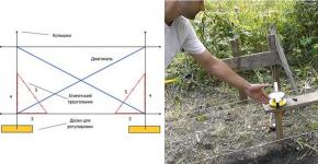
In fact, it is a movable closing element (contact) that moves vertically depending on the water level. Its secret lies in the presence of a magnet on it! You can use the simplest magnet - from a magnetic latch.
The device of the switch itself is clear from the sketch. Two contacts of the switch are half rings made of steel. You can cut into two halves a massive steel washer M16-M20, better reinforced. They are glued with epoxy resin or screwed with countersunk screws to the dielectric substrate. The wires from the network and the electric pump are also brought to them. A hole is drilled in the substrate between these “horseshoes”, through which the float guide rod will go up and down. It should also be made of a non-conductive material, preferably one that does not absorb moisture.
At the end of the rod, a closing contact is strengthened with a self-tapping screw. This is a metal round plate made of tinned tin, copper, duralumin, aluminum, but rather thin. Its size should be such that it would be guaranteed to close both half rings at once, closing the electrical circuit. A magnet is fixed on top of the plate (glue, epoxy, bracket ...)
The rod is passed through a guide pipe fixed on the wall of the storage tank, and a float is fixed on it from below. The float should have a long, elongated shape and be fixed vertically on the rod.

The operation of this circuit breaker is based on the fact that the force of pushing the float out of the water (Archimedes force) has a linear dependence on the depth of the float. Those. it increases or decreases linearly. And the force of magnetic attraction decreases (arrives) according to a quadratic law! Inversely proportional to the square of the distance between a magnet and whatever it is attracted to.
It is almost impossible to balance these forces with each other. It is enough to "shift" everything by one micron, by 1 nanometer - and immediately an avalanche-like development of events occurs and the victory of one of the forces. No intermediate position is possible.
The switch works like this. When the tank is full, the float floats at the very top of the water, submerged enough to compensate for the weight of the rod and magnet. The magnet is located high enough above the platform with contacts. As the water is used up, the float (both the rod and the magnet, of course) sinks lower and lower. In the end, at some distance from the "horseshoes" magnet begins to appear and the force of attraction of the magnet to them. And when it becomes greater than the Archimedes force acting on the float, the magnet accelerates very sharply and instantly and reliably sticks to the forgings of the contacts. Contacts, of course, are closed in this case. The pump turns on when water begins to flow into the tank.
As its level rises, the float is immersed in water more and more. And the buoyant force of Archimedes is also growing. But it is not strong enough to tear the magnet from the horseshoes. But when it exceeds this separation threshold, the magnet will still come off. And it will not just come off - it will bounce off like a bullet! By the way, it will be necessary to put some kind of damper (spring or sponge) at the bottom of the guide tube.
As you understand, the effect of the toggle switch is absolute, and the hysteresis loop depends on the attractive force of the magnet, the shape and size of the float. Therefore, here you have to experiment, choosing a float for the parameters you need.
Of course, since the switch operates with a voltage of 220 volts, all measures must be taken to ensure that the switch does not come into contact with water. It is advisable to close the container. Put on some kind of spring on the float or place some kind of limiter for the "jump" of the rod up when opening above the switch. Close the switch to protect it from atmospheric precipitation.
You can ask questions about this switches and discuss other questions about water automation and automatic irrigation systems.
When it becomes necessary to control the liquid level, many do this work manually, but this is extremely inefficient, takes a lot of time and effort, and the consequences of an oversight can be very expensive: for example, a flooded apartment or a burned-out pump. This can be easily avoided by using float switches. These devices are simple in design and principle of operation, affordable.
At home, sensors of this type allow you to automate processes such as:
- control of the liquid level in the supply tank;
- pumping groundwater from the cellar;
- turning off the pump when the level in the well falls below the permissible level, and some others.
The principle of operation of the float sensor
An object is placed in a liquid that does not sink in it. It can be a piece of wood or styrofoam, hollow plastic sphere or metal and much more. When the liquid level changes, this object will rise or fall with it. If the float is connected to the actuator, it will act as a water level sensor in the tank.
Equipment classification
Float sensors can independently control the liquid level or send a signal to the control circuit. According to this principle, they can be divided into two large groups: mechanical and electrical.
Mechanical devices
 Mechanical valves include a wide variety of float valves for the water level in the tank. The principle of their operation is that the float is connected to the lever, when the liquid level changes, the float moves up or down that lever, and he, in turn, acts on the valve, which shuts off (opens) the water supply. Such valves can be seen in toilet cisterns. They are very convenient to use where you need to constantly add water from the central water supply system.
Mechanical sensors have a number of advantages:
- simplicity of design;
- compactness;
- safety;
- autonomy - do not require any sources of electricity;
- reliability;
- cheapness;
- ease of installation and configuration.
But these sensors have one significant drawback: they can control only one (upper) level, which depends on the installation site, and regulate it, if possible, then within very small limits. On sale such a valve can called "float valve for tanks".
Electrical sensors
 An electric liquid level sensor (float) differs from a mechanical one in that it does not shut off the water itself. The float, moving when the amount of liquid changes, acts on the electrical contacts that are included in the control circuit. Based on these signals, the automatic control system decides on the need for certain actions. In the simplest case, such a sensor has a float. This float acts on the contact through which the pump is turned on.
Reed switches are most often used as contacts. A reed switch is a sealed glass bulb with contacts inside. The switching of these contacts occurs under the action of a magnetic field. Reed switches are miniature in size and can be easily placed inside a thin tube made of non-magnetic material (plastic, aluminum). A float with a magnet moves freely along the tube under the action of the liquid, when it approaches, the contacts are triggered. The whole system is installed vertically in the tank. By changing the position of the reed switch inside the tube, you can adjust the moment of operation of the automation.
If you need to monitor the upper level in the tank, then the sensor is installed at the top. As soon as the level falls below the set level, the contact closes and the pump turns on. Water will start to increase and when the water level reaches the upper limit, the float will return to its original state and the pump will turn off. However, such a scheme cannot be applied in practice. The fact is that the sensor is triggered at the slightest change in level, after which the pump turns on, the level rises, and the pump turns off. If the water flow from the tank is less than supply, a situation arises when the pump constantly turns on and off, while it quickly overheats and fails.
 Therefore, water level sensors to control the pump work differently. The container has at least two contacts. One is responsible for the upper level, it turns off the pump. The second defines the position of the lower level, upon reaching which the pump turns on. Thus, the number of starts is significantly reduced, which ensures reliable operation of the entire system. If the level difference is small, then it is convenient to use a tube with two reed switches inside and one float that switches them. With a difference of more than a meter, two separate sensors are used, installed at the required heights.
Despite the more complex design and the need for a control circuit, electric float sensors allow you to fully automate the process of controlling the liquid level.
If you connect light bulbs through such sensors, then they can be used to visually control the amount of liquid in the tank.
Homemade float switch
If you have the time and desire, then the simplest float water level sensor can be made by hand, and the cost of it will be minimal.
mechanical system
 In order to make it as easy as possible design, we will use a ball valve (faucet) as a locking device. The smallest valves (half-inch and smaller) work well. Such a faucet has a handle with which it closes. To convert it into a sensor, it is necessary to lengthen this handle with a strip of metal. The strip is attached to the handle through holes drilled in it with appropriate screws. The cross section of this lever should be minimal, but at the same time it should not bend under the action of the float. Its length is about 50 cm. The float is attached to the end of this lever.
Can be used as a float use a 2 liter plastic bottle from soda. The bottle is half filled with water.
You can check the operation of the system without installing it in the tank. To do this, install the crane vertically, and put the lever with the float in a horizontal position. If everything is done correctly, then under the influence of the mass of water in the bottles, the lever will begin to move down and take a vertical position, and the valve handle will turn with it. Now submerge your device in water. The bottle should pop up and turn the valve knob.
Since the valves vary in size and the force required to switch them, it may be necessary to adjust the system. If the float cannot turn the valve, you can increase lever length or take a larger bottle.
We mount the sensor in the tank at the required level in a horizontal position, while in the vertical position of the float the valve must be open, and in the horizontal position it must be closed.
Electrical type sensor
For self-manufacturing of the sensor of this type, in addition to the usual tool, you will need:

The manufacturing sequence is as follows:

 When the liquid level changes, the float moves with it, which acts on the electrical contact to control the water level in the tank. The control circuit with such a sensor may look like the one shown in the figure. Points 1, 2, 3 are the connection points for the wire that comes from our sensor. Point 2 is the common point.
Consider the principle of operation of a homemade device. Let's say when the tank is turned on empty, the float is in the low position (LL), this contact closes and energizes the relay (P).
The relay is activated and closes contacts P1 and P2. P1 is a self-locking contact. It is needed so that the relay does not turn off (the pump continues to work) when the water starts to arrive and the NU contact opens. Contact P2 connects the pump (H) to the power supply.
When the level rises to the upper value, the reed switch will work and open its VU contact. The relay will be de-energized, it will open its contacts P1 and P2, and the pump will turn off.
 With a decrease in the amount of water in the tank, the float will begin to descend, but until it takes the lower position and closes the HL contact, the pump will not turn on. When this happens, the cycle of work will repeat again.
This is how the water level control float switch works.
During operation, it is necessary to periodically clean the pipe and the float from contamination. Reed switches withstand a huge number of switchings, so such a sensor will last for many years.