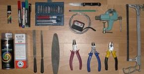
DIY soldering station for a soldering iron. Hot air soldering station "didav"
I’ve been wanting a soldering station for a long time, or rather a soldering iron with thermal stabilization. Our soldering irons cost from 3500 rubles, of course it’s expensive and it’s a pity to spend that kind of money. But the soldering irons themselves are sold from the stations and they cost pennies. I bought myself the simplest soldering iron for 500 rubles LUT0035, there is nothing on the Internet about this model, only the soldering iron label says 24V 48V. I brought him home and began to wise up. First of all, I determined the parameters for my soldering station:
— Temperature adjustment 180-360C
— Limiting current consumption for a soldering iron
— Ability to put the soldering iron into standby mode
I defined the parameters and moved on to the schematic
I decided to assemble everything using a PWM TL494; it has everything you need: two error comporators and duty cycle adjustment via the 4th DT pin. I’ve already drawn up the diagram, calculated almost all the wiring around the TL494 and it turned out that it won’t be enough for me. The soldering iron I purchased uses a thermocouple instead of a thermistor to detect temperature, and I had to add a voltage amplifier using an additional LM358 op-amp. In the end, this is the diagram we got:
There's nothing special about the diagram. A voltage of approximately 0.025V at 350C is taken from the Thermocouple and multiplied by an amplifier on LM358 approximately 140 times and divided in half by a divider R6R16
Using variable resistor R8, the required threshold voltage is set on the 2nd leg of the error comporator, equal to approximately 1.75V. Until the potentials between the first and second legs are leveled, the PWM will simulate pulses on the control transistor T1. The transistor took IRF630
Button S1 is installed on the lever-stand for the soldering iron; when the button is closed, the pulse width is limited and current consumption drops by about half, which saves the life of the soldering iron
R12R13 is a divider that determines current consumption and is set to a voltage of 0.2V, which, with a shunt of 0.1 Ohm, maintains a current of approximately 2A. I wanted to limit the current in order to save the life of the soldering iron and transformer
The transformer was taken with two serial windings of 17V each with a common point and made with a filter capacity of 4700 μF. The microcircuits were powered through Kren 7812
To indicate heating, I placed a red LED parallel to the heater.
Well, a couple of photos of the soldering station


In principle, that's all, everything is elementary. The soldering iron works as expected. Heats up from room temperature to 200C in 85 seconds, to 350C in about 215 seconds
I tried to melt refractory solder, which a 25W mains soldering iron could not handle. The station melted without problems, massive tracks and parts of the KU202 type in an iron case are soldered easily
In general, I was pleased with the homemade soldering station. The only thing I’m not happy with is the soldering iron tip, I need to buy something convenient

Download PCB
Read
With uv. Admin check
Hi all! We are adding a homemade tool to our laboratory - this time it will be a homemade DSS digital soldering station. I had never had anything like this before, so I didn’t understand what its advantages were. Having scoured the Internet, on the Radiokota forum I found a diagram that used a soldering iron from a Solomon or Lukey soldering station.
Before this, I always soldered with a soldering iron like this, with a step-down block, without a regulator and, of course, without a built-in thermal sensor:

For my future soldering station, I bought a modern soldering iron with a built-in thermal sensor (thermocouple) BAKU907 24V 50W. In principle, any soldering iron you like, with a thermal sensor and a supply voltage of 24 volts, will do.

And work began slowly. I printed out the signet for LUT on glossy paper, transferred it to the board, and etched it.

I also made a drawing for the back side of the board, for the location of the parts. It's easier to solder, and it looks nice.


The board was made with dimensions of 145x50 mm, under a purchased plastic case, which had already been purchased earlier. I soldered in the parts that were available at that time.
R1 = 10 kOhm
R2 = 1.0 MOhm
R3 = 10 kOhm
R4 = 1.5 kOhm (selectable)
R5 = 47 kOhm potentiometer
R6 =120 kOhm
R7 = 680 Ohm
R8 = 390 Ohm
R9 = 390 Ohm
R10 = 470 Ohm
R11 = 39 Ohm
R12 =1 kOhm
R13 = 300 Ohm (selectable)
C1 = 100nF polyester
C2 = 4.7 nf ceramics, polyester
C3 = 10 nF polyester
C4 = 22 pf ceramic
C5 = 22 pf ceramic
C6 = 100nF polyester
C7 = 100uF/25V electrolytic
C8 = 100uF/16V electrolytic
C9 = 100nF polyester
C10 = 100nF polyester
C11 = 100nF polyester
C12 = 100nF polyester
T1 = triac VT139-600
IC1 = ATMega8L
IC2 = unlocked MOS3060
IC3 = 5v 7805 stabilizer
IC4 = LM358P op. amplifier
Cr1 = quartz 4 MHz
BUZER = signaling device MSM-1206A
D1 = LED red
D2 = LED green
Br1 = 1 A bridge.

To make the board compact, I made the board so that Mega8 and LM358 would be located behind the display (I use this method in many of my crafts - it’s convenient).


The board, as I already said, has a length of 145mm, suitable for a ready-made plastic case. But this is just in case, because there was no power transformer yet and it mainly depended on what the final version of the case would be. Or it will be a power supply case from a computer, if the transformer does not fit into the plastic case, or if it does, then a ready-made plastic one purchased. For this reason, I ordered a TOP 50W 24V 2A transformer via the Internet (they wind to order).


After the transformer was at home, the final version of the housing for the soldering station immediately became clear. In terms of dimensions, it should have fit into the plastic. I tried it on in a plastic case - it fits in height, there is even a small margin.


As I already said, when I was developing the board, I first of all, of course, took into account the dimensions of the plastic case, so the board fit into it without any problems, I just had to cut the corners a little.


The front panel for the soldering station, as in my other crafts, was made from 2mm acrylic (plexiglass). I made my own using the original plug. I don’t remove the film until the end of the work, so as not to scratch it again.


I flashed the controller and assembled the board. Test connections of the finished board (without a soldering iron so far) were successful.

ATTENTION! Before connecting your LCD, study the datasheet for it!! Especially pins 1 and 2!" The board was designed for LCD Winstar WH1602D. Even this manufacturer's displays have a difference between B and D.
The diagram shows an indicator, pin 1 of which is supplied with +5V, and pin 2 is common!
Your indicator may differ in the pinout of these pins (1 - common; 2 - + power supply).
I assemble all the components of the soldering station into one whole. For the soldering iron I installed a “Solomonovsky” connector (socket).

The time has come to connect the soldering iron itself and here the bummer is the connector. Initially, such a connector was installed in the soldering iron.

I went to the store to get a connector. I couldn’t find the answering part in stores in our city. Therefore, I left the socket in the station as it was, and soldered the connector on the soldering iron to our Soviet one from tape recorders (SG-5, I think, or SR-5). Perfect fit.

Now we pack everything into the case, finally attach the transformer, the front panel, and make all the connections.


Our design takes on a finished look. It turned out not big, it won’t take up much space on the table. Well, the final photos.


How the station works, you can watch this video, which I uploaded to YouTube.
If you have any questions about assembly or setup, ask them, I will try to answer if possible.
P.S.
For setup:
1. Determine where the soldering iron has a heater and where the thermocouple is. Measure the resistance at the terminals with an ohmmeter, where the resistance is lower, there will be a thermocouple (the heater usually has a resistance higher than the thermocouple, a thermocouple has a resistance of one ohm). The thermocouple must be connected in the correct polarity.
2. If the resistance of the measured leads is practically the same (powerful ceramic heater), then you can determine the thermocouple and its polarity in the following way;
- heat the soldering iron, turn it off and use a digital multimeter at the lowest range (200 millivolts) to measure the voltage at the soldering iron terminals. There will be a voltage of several millivolts at the thermocouple terminals, the polarity of the connection will be visible on the multimeter.
3. If on all soldering iron leads the measured resistance (in pairs) is greater than 5-10 Ohms (or more) on two paired leads (heater and the desired thermocouple), then perhaps the soldering iron has a thermistor instead of a thermocouple. You can determine it using an ohmmeter; to do this, measure the resistance at the terminals, remember it, then heat the soldering iron. We measure the resistance again. Where the value of the readings changes (from what was remembered), there will be a thermistor.
The figure below shows the pinout of the Solomon soldering iron connector

4. Select the value of R4.
The attached archive contains all the necessary files.
Archive for the article
Anyone who has tried to repair electronics has come to the realization that a soldering iron alone will not be enough. Some SMD elements simply cannot be desoldered without the help of a hot air dryer. That is why, over time, a soldering station is purchased that includes both. Most cheap options rarely meet individual preferences. Therefore, a do-it-yourself hot-air soldering station is not something unattainable. The article will discuss various options for soldering stations, as well as the self-assembly process.
What is a soldering station
To put it simply, a simple soldering station consists of several main blocks:
- power unit;
- Control block;
- indicators;
- manipulators.

The power supply can be switching or transformer. The first has smaller dimensions and is capable of delivering more power. The transformer power supply has a characteristic sound during operation and requires large dimensions for high power. In some cases, the transformer unit proves to be more reliable, but this directly affects the weight and dimensions of the soldering station. The soldering station control unit consists of a board on which there are microcontrollers, variable resistors and other elements that are responsible for feedback, as well as for generating the output signal for the manipulators.
The following can be used as manipulators at a soldering station:
- soldering iron;
- infrared head.
There are indicators on the front panel of the station. They display readings from temperature sensors located in the manipulators. In most cases, additional calibration is required to achieve correct readings.
Types of stations

All soldering stations can be divided into two large groups:
- hot air;
- infrared.
Each of them is tailored to its own tasks. In most cases, professional repairs require both types of soldering stations. The first is a small block that has one or two manipulators. A hot air soldering station can include only a hair dryer or a hair dryer with a soldering iron. There are soldering stations that only have a soldering iron as a manipulator. Usually these are the varieties that are called induction. In conventional hot-air stations, the soldering iron is heated by a ceramic or similar element to which voltage is applied. This element transmits temperature to the tip. In induction soldering stations, heating occurs due to the action of an electromagnetic field. The energy is immediately transferred to the sting.

Thanks to this approach, it was possible to reduce the inertia of the soldering station, increase the response time, and also increase power with smaller dimensions. In those products that contain heat-intensive elements, it is impossible to do without an induction station, since it is capable of heating large areas of tin in a short time. In some cases, this is difficult to achieve even with a hot-air hair dryer. Induction units are several times more expensive than conventional stations, but their efficiency guarantees pleasure and high precision when working.
Infrared soldering stations are a separate division. In appearance, they are practically different from the two previous types. They consist of two main modules:
- head or top heating;
- bottom heating.

Heating in them occurs due to infrared elements. Thanks to the bottom heating, the board is heated evenly, which avoids deformation when removing or sealing certain elements. Most often, infrared stations are used to replace chips with BGA soldering. They are chip-crystals that are fixed on the board using special solder balls. Some types of such chips can be replaced with a conventional hot air station, but the quality will suffer. The cost of a good infrared station starts from one thousand dollars.
Note! There is a separate subtype of infrared stations, in which the infrared element is placed in a manipulator that resembles a hair dryer. Such products are not widely used and are rarely used.
Self-assembly
Two of the listed types of soldering stations can be assembled yourself. In most cases, ready-made modules that are commercially available are used. If you wish, you can develop your own circuit and assemble it, but often this is not necessary, since it is cheaper to buy ready-made components.
Thermal air

The simplest hot air soldering station can be assembled from a regular soldering iron. Below you will find instructions in photographs on how to do this. The entire assembly process will require the following components:
- soldering iron with wooden handle;
- aquarium compressor;
- screwdriver;
- drill;
- medical IV;
- foil;
- antenna part;
- stranded wire.
The process begins with the need to disassemble the soldering iron. The screw is unscrewed and the tip is released.

The next step is to remove the handle, which will be needed later. The wires that connect the power cable to the heating element are unscrewed.

The wire is pulled out of the handle and a small hole is drilled in the side.

The power wire is inserted through the hole made. To make this easier, you can tie it to a piece of wire and stretch it through it.
Now you will need the previously prepared dropper. The part on which the elastic is located must be cut in half, as shown in the photo.

After this, the remaining part with the tube is inserted into the handle, where the power cord used to go.

The connection turns out to be quite reliable and airtight. Next, the heating element removed earlier is connected to the power wire, which was threaded into the drilled hole.

It is important to insulate the wires well to avoid electric shock. The heating element is installed in its place. After this, a piece of foil is wrapped around the holes in the heating element, which are intended for cooling, as shown in the photo.

To keep the foil in place, it must be secured with copper wire wrapped around the foil.

The nozzle, which will provide a directed air flow, is made from a piece of tube from the antenna. It is simply inserted into place of the sting, as shown in the photo below.

The hole through which the power wire passes must be well sealed. A regular sealant will do for this purpose. Next, the aquarium compressor is connected to the second part of the tube from the dropper.


This result will be quite sufficient for working with small components on boards. The power of such a hair dryer can be increased by winding a nichrome thread on a heating element, and also by installing a compressor with higher performance. In conjunction with a hairdryer, you can use a regular soldering iron. You can always take such products with you.

The process of assembling a product with a more complex structure is described in the video below.
Infrared
It is also quite possible to make an infrared station yourself. For this purpose you will need:
- soldering iron;
- PC power supply;
- car cigarette lighter.
You can use the old power supply. You only need one working line with a voltage of 12 volts. No special power required. The only thing you need for a soldering iron is a wooden handle. It can be used from any other device or made independently. The first step is to disassemble the cigarette lighter to get to the heating element that is located inside. The photo shows what it looks like.

The next task is to attach the cigarette lighter handle to the soldering iron handle. You can use glue for this. Next, you need to drill a hole in the cigarette lighter handle so that the power wires can be fed through the hole. Once the wires are connected, you can assemble the cigarette lighter module with a ceramic spacer, as shown in the photo below.

The entire structure can be secured to the handle using an additional metal plate. When everything is ready, the wires are connected to the power supply to a 12 volt output. The finished version of the mini-station is shown in the photo below.

The station turns out to be compact, so it is easy to transport and can be powered from any source that is capable of delivering 12 volts DC. It could even be a battery, so the station turned out to be completely autonomous. If you assemble a small block of 18650 lithium-ion batteries with a 12-volt converter and install a charging controller, then the price of such a station will not be.

The mini-station heats up almost instantly, and the maximum temperature can exceed 400 degrees. Small elements such as capacitors and transistors can be desoldered, as can be seen in the photo below.

The distance to the board when soldering must be at least 10 mm. In addition to miniature SMD elements, the station can easily cope with microcircuits in SOEC packages. The photo below shows direct evidence of this.

You can also desolder larger components without much difficulty. The station can be slightly modified to make it a convenient option for work. One of the modules that is easy to use additionally is a dimmer, as can be seen in the photo below.

Its purpose is to be able to adjust the power of the soldering station. As a power source, you can use not a power supply from a PC, but a power supply for an LED strip, as can be seen in the photo below. It is easy to purchase at any electrical goods store. The total power of the station is approximately 50 W, the current required for its operation reaches 6 amperes. This should be taken into account when choosing a power supply.

The disadvantage of such a soldering station can be considered the lack of contact with the element that is being soldered. Because of this, there is no way to remove excess solder, and it is also impossible to correct the part if it was positioned offset and the solder has not yet cooled. It is advisable to provide a separate power button on the handle, which will prevent the cigarette lighter from overheating. While operating such a station, it is necessary to hold the manipulator at an angle of 90 degrees to the element that is being soldered. This will make it possible to influence it evenly with the entire area of the heater.

Additionally, for successful soldering of small elements you will need a set of tweezers. Their jaws must be sharp to make it easier to grip miniature components. In addition, you cannot do without a device called a “third hand”. There are many variations of it, but the main purpose is the same everywhere. It consists of holding soldered wires or entire microcircuits. To make it easier to see small components, you need a good magnifying glass or microscope. An integral part of the master's toolkit is good lighting. It would be desirable if it were based on LEDs that do not flicker during operation. When soldering using a station, you cannot do without flux. This is a special solution that improves adhesion and cleans the metal for soldering. A variant of an infrared soldering station with bottom heating can also be assembled independently. There is a video about this below.
Summary
As you can see, building your own soldering station is not as difficult as it might seem. At the same time, the costs for such a soldering station will be minimal, and it can be used anywhere. If we are talking about a professional level of repair work, then it makes sense to think about purchasing a high-quality factory soldering station, which has various operating modes and settings. When learning, there is no point in buying an expensive soldering station; you can start with cheap options for soldering stations. If the training is successful and during this time the desire to work is not lost, then you can think about purchasing a professional soldering station.
Good day to all, dear radio amateurs! I offer everyone a simple diagram of a soldering station with a hair dryer. I've had an idea for a long time to make a soldering station, with my own hands. It was not advisable for me to buy in a store, since I was not satisfied with the price, quality, management, or reliability. After a long search on the Internet, I found, in my opinion, the best and one-of-a-kind circuit using an atmega8 microcontroller and a WH1602 two-line LCD display, with encoder control. The project is new and is not a clone of the same “worn out” schemes; in general, it has no analogues.
Device Features
The station has the following advantages:
- Settings menu.
- Two “memory” buttons, that is, two preset temperature modes for a soldering iron and a hair dryer.
- Sleep timer, you can set the timer in the settings.
- Digital calibration of the soldering iron is also found in the settings.
- Built on budget components.
- I designed the printed circuit board for the PC case from the PSU, so there won’t be any problems with the case either.
- To power the station, you can use the same board from the PC unit, slightly altering it to the required 20-24v (depending on the transformer), fortunately the dimensions of the case allow this. We can shorten the radiators a little, since we only need 24v and 2-3 amperes for power supply and there will be no strong heating of the power transistors and diode assembly.
- The firmware contains a “Pi” algorithm for regulating the heating of the hair dryer, which provides uniform heating of the hair dryer coil and cuts off IR radiation when the hair dryer is turned on. In general, if you use a hairdryer skillfully, not a single part will be “fried” ahead of time.
Schematic diagram
Initially, in the author's version, the circuit was made entirely on SMD components (including atmega8) and on a double-sided board. It is not possible to repeat it for me, and I think for most radio amateurs. Therefore, I translated the circuit and developed a board based on DIP components. The design is made on two printed circuit boards: the high-voltage part is made on a separate board to avoid interference and interference. The soldering iron is used with a thermocouple, 24v 50w from the "Baku" station.
The hair dryer is from the same company, with a thermocouple as a temperature sensor. It has a nichrome heater with a resistance of about 70 ohms and a 24v “turbine”. The screen displays the temperature: set and actual for the hair dryer and soldering iron, the strength of the air flow of the hair dryer (displayed as a horizontal scale in the bottom line of the screen).


To increase or decrease the temperature and air flow of the turbine: move the cursor by briefly pressing the encoder, and turning left or right sets the desired value. By holding the first or second memory button, you can remember the temperature that is convenient for you and the next time you use it, pressing the memory will immediately heat up to the values set in the memory. The hair dryer is started by pressing the "Fen ON" button, which is located on the front panel, but you can display it on the handle of the hair dryer using the wiring going to the reed switch, since it is not used in this station. To switch the hair dryer to sleep mode: you also need to press the “Fen ON” button, this will stop heating the hair dryer, and the hair dryer’s turbine will cool it to the set temperature (from 5 to 200 degrees), which can be set in the settings.
Station assembly
- We make the main board according to the folk recipe ""
- We drill and tin the finished scarf.
- We solder in the 7805 stabilizer, shunt capacitors, a jumper under the socket for the MK and the rest of the jumpers, the socket and shunt capacitors near the socket.
- We connect the 24v power supply, check the voltage after 7805 and on the MK socket. We make sure that there is +5V on pins 7 and 20, and minus 5v on pins 8 and 22, that is, GND.
- We solder the direct connection between the MK and LCD 1602, which is necessary for the first launch of the circuit. And these are: R1, R2, trimmer (to adjust the screen contrast, available on the printed circuit board), encoder with buttons S1 and S2 (these components are soldered on the track side).
- We solder the wires to the screen, 10 wires in total. The contacts on the screen itself: VSS, K, RW - must be connected together using wires.
- Flashing atmega8. Configuration bytes: 0xE4 - LOW, 0xD9 - HIGH
- We connect the power, the circuit is in sleep mode. When you briefly press the encoder, the backlight should light up and a greeting message should appear. If this does not happen: look at the 2nd leg of the MK after switching on there should be a stable +5V. If not, look at the atmega8 harness and fuses. If there is +5v - wiring the indicator. If there is a backlight, but no characters, turn the screen contrast adjuster until they appear.
- After a successful test run: we solder everything except the high-voltage part on a separate board.
- We launch the station with a soldering iron connected and admire the result.
- We make a scarf for the high-voltage part of the circuit. We solder the parts.


Starting the soldering station
First start with high voltage part:
- We connect the thermocouple of the hair dryer and the impeller to the main board.
- We connect a 220v incandescent lamp, instead of a hair dryer heater, to a high-voltage socket.
- Turn on the station, start the hair dryer with the "Fen ON" button - the lamp should light up. Turn it off.
- If it doesn’t “bang” and the triac is not hot (it is advisable to attach it to the radiator) - connect the heater of the hair dryer.
- We are launching a hairdryer station. We admire the work of the hairdryer. If there is an extraneous sound (squeaking, grinding) in the triac area, select capacitor C3 in the triac snubber, from 10 to 100 nanofarads. But I’ll be honest and say right away - bet 100n.
- If there is a difference in the temperature readings of the hair dryer, you can correct it with resistor R14 in the op-amp harness.


Replacing parts
Some substitutions of active and not so active components:
- Op-amp - Lm358, Lm2904, Ha17358.
- Field-effect transistors - Irfz44, Irfz46, Irfz48, Irf3205, Irf3713 and the like, suitable for voltage and current.
- Bipolar transistor T1 - C9014, C5551, BC546 and the like.
- Optocoupler MOC3021 - MOC3023, MOC3052 without zero crossing (without zero cross according to the datasheet).
- Optocoupler PC817 - PC818, PC123
- Zener diode ZD1 - any for stabilization voltage from 4.3 - 5.1V.
- I used an encoder with a button from a car radio.
- The capacitor in the triac snubber is required for 400v and 100n!
- LCD WH1602 - look carefully at the location of the contacts when connecting to the main board; it may differ from different manufacturers.
- For power supply, the best option would be a stabilized 24V 2-4A power supply from one large eastern store or a converted ATX power supply. Although I used 24V 1.2A from the printer, it gets a little warm when using a soldering iron, but it’s enough for me. At worst, a transformer with a diode bridge, but I don’t recommend it.
Station body


I have a PC case from a PSU. The panel is made of plexiglass; when painting, it is necessary to leave a window for the screen by gluing masking tape on both sides. The body is painted with one coat of primer and two coats of matte black spray paint. The soldering iron uses a Soviet five-pin plug from a tape recorder. The hair dryer is not disconnected; it is connected directly to the main board with pins. The soldering iron socket, hair dryer cord and power cord are located on the rear wall of the case. The front panel contains only controls, a screen, a power switch and an indicator for the hair dryer. My first design was with a panel made of textolite, with etched inscriptions, but unfortunately there are no photos left. The archive contains drawings of printed circuit boards, a drawing of a panel, a diagram in Splan and firmware.
Video
P.S. The station is called " Didav" is the pseudonym of the person who created the circuit and firmware for this device. Happy soldering to everyone without "snot". Addition on the circuit and firmware. Especially for the site - Akplex.
Discuss the article HOT-AIR SOLDERING STATION "DIDAV"
Modern, more advanced equipment, alas, fails no less than older models. And if earlier the question of improving what was familiar was not a question for us, today it is almost impossible to unsolder or solder a part the old fashioned way without “hitting” neighboring chips. That is why craftsmen assemble more modern hot-air and infrared soldering stations with their own hands. In this review we will tell you what soldering systems are, how the control unit works and how to connect it, what is included in the design elements. Only in our review you will find recommendations illustrating the features of assembling and adjusting modern soldering stations.
Read in the article
What is a soldering station for?
A soldering station, unlike a simple soldering iron, is a more advanced system. It allows you to solder small parts, such as SMD components, control the heating on the display, and program buttons. In addition, thanks to the non-contact soldering system, overheating of neighboring elements is excluded.

A non-contact type soldering station is one of the modern soldering systems. For example, heating with a hot air gun helps craftsmen repair household electrical appliances and mobile phones. But with the help of IR systems you can perform installation and disassembly (even in BGA format).
General characteristics and operating principle of the soldering station

The anatomy of a soldering station is quite simple and best meets the necessary conditions: accurate, “smart” soldering of elements. The heart of the device is, inside which there is a transformer that produces two voltage options: 12 or 24 Volts. Without this element, all station systems would be useless. The transformer is responsible for regulating the temperature. The power supply is equipped with a thermostat and special buttons to start the device.
For reference! Some devices are equipped with a special stand that heats the printed circuit board during soldering, which helps to avoid its deformation.
Using the control unit, the function of storing temperature and programming buttons can also be implemented. Craftsmen “pump” the device using a processor, which makes it possible to measure temperature during soldering.

Let's look at the operating features of a hot air soldering station: the air flow is heated using special spiral or ceramic elements (they are located right inside the hot air gun tube) and then directed through special nozzles to the soldering point. This system allows you to heat the required surface evenly, eliminating point deformation.

A comment
Ask a Question“The temperature that modern soldering hair dryers, including those assembled by yourself, can provide varies from 100 to 800°C. Moreover, these indicators can be adjusted by the operator.
"Another additional element can be a special infrared heater. Its principle is similar to the operation of a hot air gun; it heats not the joint, but a certain area. However, unlike a hot air gun, there is no flow of warm air. Professional soldering stations can be equipped with special accompanying tools, desoldering pumps and vacuum tweezers.
Types of soldering stations by design
There are both simple soldering stations equipped with the classic soldering iron we are used to, as well as more advanced ones. Moreover, there can be a great variety of variations in the combination of components and systems. You can easily combine a contact soldering iron and a hair dryer, a vacuum or thermal tweezers and a desoldering pump in one station. For convenience, we provide a table of the main types of soldering stations.
| Contact PS is an ordinary soldering iron that has direct contact with the surface when soldering, equipped with an electronic control and temperature control unit. | Contactless PS - at the heart of the work control unit and special system control elements. |
|||
| Lead | Lead free Requires elevated melting temperatures. | Thermal air Provide effective soldering in hard-to-reach areas with simultaneous heating of several surfaces at once. Allows you to carry out soldering of any type, both with and without lead. | Infrared There is a heating element in the form of an infrared emitter made of ceramic or quartz. | Combined They combine several types of equipment in their design: a hair dryer or a classic soldering iron, or, as we have already said, an IR heater and a desoldering pump, for example, a soldering iron and a hair dryer. |
Based on the temperature stabilization mechanism and the operating principle of the control units, soldering stations can also be divided into analog and digital. In the first case, the heating element is turned on until the soldering iron warms up to the desired temperature; the closest analogy is heating a regular iron. But the second type of soldering iron is distinguished by a complex system of temperature control and regulation. A PID controller is located here, which obeys the microcontroller program. This method of temperature stabilization is much more effective than the analog one. Another classification allows us to divide all substations into installation and dismantling. The first ones carry out soldering of devices, however, they do not have a desalinizer and other elements that allow cleaning and replacing parts.

Such soldering systems are equipped with a special container for removing solder, which, in turn, is sucked out by a special nozzle equipped with a compressor.
For your information! There are combined stations that allow both installation and dismantling work. They are equipped with two types of soldering irons, differing in power.
How to make your own hot air soldering station
Not everyone can afford to buy a soldering station with a hair dryer, although IR stations cost even more money, so the easiest way is to assemble it yourself. However, it should be remembered that such air soldering stations have certain disadvantages:
- The air flow may accidentally blow away small parts.
- The surface is heated unevenly.
- Additional attachments are required for different cases.
DIY soldering gun: universal circuit
A hot air gun is a special device that heats the soldering area with a stream of hot air.
The easiest way is to assemble the device with a hairdryer on a fan, and use a coil as a heater.

If you buy a mechanical heater, it is quite expensive. And with sudden temperature changes, it can simply crack. Not everyone can design a compressor on their own. An ordinary small-sized fan can be used as a blower. A cooler from a home PC will do. To get acquainted with the structure of such a device, let’s study the diagram of a soldering station with our own hands.

We will place the fan near the hot air gun. We carefully attach a tube to it to supply warm air. At the end of the cooler we make a hole for the nozzle. On the opposite side, the cooler must be closed to provide the necessary draft.

Now it’s time to assemble the heating element. To do this, you need to wind the nichrome wire in a spiral onto the base of the heater. Moreover, the turns must not touch each other. The turns are wound taking into account that the resistance should be 70-90 Ohms. The base is chosen with poor thermal conductivity and good resistance to high temperatures.
A comment
Electrician 5th category LLC "Petrocom"
Ask a Question“Some of the parts can be borrowed from a regular hair dryer. In particular, a mica plate is suitable as a base for a spiral with low thermal conductivity.
"Let's start looking for parts for the nozzle. A ceramic or porcelain pipe is best suited for this. Leave a small gap between the walls of the nozzle and the spiral. We wrap the top surface with insulating materials. You can use asbestos layer, fiberglass, etc. This will increase the high efficiency of the hair dryer, and will also allow you to take it with your hands without getting burned. We fasten the heating element so that air is supplied to the tube, and the heater is located exactly in the middle inside the nozzle.
Soldering station control system
To assemble a control system for a homemade soldering station such as a hair dryer with your own hands, you need to place two rheostats in it: one regulates the incoming flow, the other regulates the power of the heating element. But usually one is made for both the heater and the blower.

Here it is very important to connect the wires correctly so that they correspond to the rheostats.
Then we attach a hot air gun so that the wires match the required rheostats and switch.
Assembling and setting up the soldering station
The power of a soldering station, as we have already noted above, is usually in the range from 24 to 40 Watts. However, if you plan to solder the power buses and, then the power of the device should be increased from 40 to 80 watts.

For more information on how to solder with a hairdryer from a soldering station, watch this video.
DIY infrared soldering station
An infrared soldering station is the easiest tool to make with your own hands. The price for soldering stations of this type is simply exorbitant. Buying something simpler is not an option, since it will still have limited functionality.

That is why we will tell you step by step how to assemble an infrared soldering iron with your own hands. Let's look at the stages of assembling a PS for soldering boards measuring 250x250 mm. Our soldering station is suitable for working with television boards, video adapters for PCs, and tablets.
Manufacturing of housing and heating elements
For the basis of a homemade IR soldering station, assembled with your own hands, you can take a door from the mezzanine or 10-12 mm, screw the legs to it. At this stage, it is important to roughly estimate the layout based on the size of the heaters and PID controllers. The height of the “sidewalls” and bevels of the front panel will depend on this.
Aluminum corners are used to form the “skeleton” of the structure. Take care of the “stuffing” in advance; old VCRs, DVD players and the like will also come in handy. You can bypass specialized street hawkers.


Now we are looking for a non-stick pan. Yes, exactly the one you can buy at a regular hardware store. Here you can also look for a high-quality soldering iron for a soldering station.
Important! Take a tape measure with you. Your task is to find a baking tray of optimal width and depth. The dimensions depend on the height of the IR emitters and their number.
Soldering machine control system
Let's get to the fun part. On the trading platform, we pre-order PIDs (or proportional-integral-derivative controllers), as well as IR - 3 lower IR emitters 60x240 mm, and one upper one - 80x80 mm, do not forget to stock up on two solid-state 40A. At this stage, it is already possible to move on to tin work, namely, to adjust the entire structure to the dimensions of our main elements. After adjusting the sidewalls and the cover, we cut out technological holes for the PIDs on the front wall, and for the cooler on the back wall.
Assembly and adjustment of the soldering station
So, after installing the emitters, cooler and connecting all the wiring, the appearance of our soldering station is almost finished. At this stage, it is necessary to test the equipment for heating, temperature retention and hysteresis. Let's move on to installing the main IR emitter. This is not difficult to do.