Equipment for digital television is what you can buy in our store. Examples of making a television splitter with your own hands Antenna splitter
For many families, it has become common to have several televisions in the apartment. A device called a television cable splitter allows you to distribute the signal received from a television antenna to several televisions.
With its help, you can watch several programs simultaneously, while the signal quality remains at the proper level. Before purchasing such a device, we recommend that you read the information in this article.
There are several types of devices, each of which is responsible for specific capabilities of the splitters.
Depending on the assigned tasks, the following are used:
- splitter;
- diplexer;
- coupler
You should familiarize yourself with each of them in more detail.
Splitter, also known as a TV signal divider between several devices. By the way, people call it TV crab
. Depending on the number of connectors, the splitter divides into 2, 3 and 4 TVs.
In the latter case, an amplifier is required, otherwise the signal will be weak.
The diplexer has another more understandable name - adder. In other words, a splitter combines several signals from different antennas and produces one more powerful one.
It can be used in a home where there is satellite TV and a regular TV antenna. Also used to combine frequencies from different ranges.
Modern splitters are in most cases universal and can work as both an adder and a divider.
The TV tap is used in apartment buildings. Part of the signal from the common antenna goes to one of the apartments, and the other goes through a coupler further.
One of its varieties is a blocker. It is used to limit paid channels.
How long do we connect TV?
In any specialized store, a sales consultant will select a good antenna splitter for 2 devices.
A good signal level for 3 TVs will be provided by a divider or adder from well-known brands, so you should not skimp on it.
In order to achieve good image quality for a splitter for 4 TVs or more, you need an amplifier (active splitter).
Depending on the number of connected monitors, the minimum required power changes.
How to choose a TV signal divider for 2 TVs

When choosing equipment, first of all you need to find out at what frequencies television channels are broadcast. You can obtain this information using a TV with a frequency detection function or a device that picks up signals of different ranges.
Also, it is necessary to take into account the number of connected TVs and the cross-sectional diameter of the antenna cable.
One important parameter is attenuation, which is expressed in decibels. You can find its value on the case. The lower its value, the better it will affect the quality when watching television programs.
Preference should be given to devices that have mounting holes in their design. A device hanging on the cable alone produces a worse TV signal than one mounted on the wall.
If there is cable distribution and ducting in the apartment, use a compact size splitter.
Depending on the type of cable, you should buy a splitter with a threaded connection or screw terminals. There are devices in stores designed to connect them to a cable using soldering.
They transmit the television signal better, but require special skills.
How to connect a TV divider to a TV
You need to calculate how long the cable will be needed. It is recommended to take the distance with reserve. The measurement should be taken from the place where the central wire ends.
If you need to combine signals from several antennas, you need to connect the antenna cables to TV signal combiners. Then, through the adapter, you need to install a divider.
If there is only one antenna, then only the last device is used.
TV crab installation
At the junction of the cables and the branching device, fixation is carried out with special nuts that come complete with the divider or adder.
The other ends of the cables must be fitted with plugs. To do this, each wire must be stripped of insulation so that the central wire of the cable protrudes from it.
It can then be connected to your TV. After turning it on, you should search for channels and check the quality of the resulting sound and image for noise.
If the condition is satisfactory or poor, then you need to install an amplifier. In the age of digital technology, the question of how to connect TVs to a computer or other device is becoming increasingly common.
This will allow you to view photos, videos, website pages on a large television screen. Walking past shelves of monitors in a computer store, you may notice that they all play the same video or image.
An HDMI splitter is used for this purpose.
Let's look at how to connect an active hdmi signal splitter to 2 TVs.
To do this, you will need a device with two outputs (OUT). If you need to connect more monitors, you should purchase an HDMI splitter with 4, 8 or 16 outputs (OUT).
Connection is quite simple. The HDMI cable from a computer or laptop must be connected to the input (IN), and the cables from monitors must be connected to the outputs (OUT).
DIY antenna splitter

Anyone can make a splitter on their own. But before you begin development, it is important to know that such a device is applicable to an analog television antenna.
It is impossible to make such a divider or adder for digital TV.
Cheap Chinese devices have large losses in transmission quality, so it would be reasonable to improve them. To do this you will need a cable and a ferrite ring.
You can assemble the antenna splitter in a small metal box, and you should pay attention to the location of each connector.
In addition, the quality of the transmitted signal from a homemade splitter can be affected by a poor connection between the plug and the socket. Also, it is worth paying attention to the cable resistance.
It would not be superfluous to ground the homemade device and insulate the cable.
How to boost the signal
For a TV with poor picture and sound, an excellent solution would be to use an amplifier. Thanks to it, you can significantly improve the quality of the transmitted image and sound.
It must be installed in close proximity to a splitter or antenna. When purchasing an amplifier, you should pay attention to the gain values in dB, acceptable noise level, signal attenuation, and the presence of a power supply.
Depending on the required ranges, different types of amplifiers are used. Not every frequency can be captured qualitatively using one or another amplifier.
The wiring diagram of devices also affects the signal.
The following schemes are used:
- with an amplifier in front of the splitter input;
- with several at each entrance;
- combination.
Antenna amplifiers come in meter and decimeter sizes. A certain model will be suitable for a specific situation. Therefore, before purchasing, it is recommended to consult with the seller or a television repairman.
The latter has the necessary equipment with which you can accurately determine what the power of the antenna, divider or adder should be.
In modern society, when most apartments have several televisions, you cannot do without a splitter. Anyone can connect the devices themselves, but before doing so, it is recommended to consult with a specialist.
When purchasing a splitter, you need to be careful and study its characteristics.
Very often, a second TV appears in one family. In this case, there is only one antenna. The question arises: how to connect two TVs to one antenna? There are ways to use one antenna on two or more TVs.
What you need
To connect, you will need several parts:
- two-output splitter (splitter). This is a device that allows you to divide the signal from the antenna into two or more streams. It has an input on one side and two or more outputs on the other - for connecting television receivers.

- 5 connectors corresponding to the splitter;
- 2 adapter plugs;

- antenna cable.
Important: When purchasing a splitter, do not confuse the number of outputs! A three-way (three-output) splitter is used to connect three receivers, but not two! If you still have a three-output one at hand, you can solve the problem by connecting a ballast resistor (resistance 75 Ohms) to the free output. And if there is a plan in the future to install and connect several TVs to this antenna, then it is better to immediately buy a splitter with several outputs and temporarily drown out the empty outputs with the same resistance.
Work progress
We will try to talk about the connection in such a way that even someone who does not understand radio engineering at all can cope with the task. This is done step by step like this:
- Selecting details. The first thing you need to do is buy a splitter. They come in a variety of varieties, including those that require soldering and those that do not. If you know how to solder, then it is better to take those that involve soldering. This connection is always more reliable than any other, it produces less signal loss and preserves its quality.
If you do not have soldering skills, then you need to choose an appropriate splitter, as well as one suitable for a specific type of cable. A win-win option would be a splitter with built-in sockets for coaxial cables.
Having chosen a splitter, select the appropriate connectors. F-connectors are now very popular due to the fact that they are reliable and easy to install.
- Choosing a location for the splitter. It is optimal to position the device so that the antenna cable can easily reach it and, if possible, have the shortest distance to both TVs.
- Cutting the existing antenna cable. It is necessary to cut so that the cable can freely reach the splitter. The old plug is cut off along with a piece of cable.
- Cable stripping and installationF– connector.

For those who know how to solder, there is no point in telling them how to cut a cable and solder it to a splitter - they know it themselves. What follows is written for the average user who is not familiar with the radio business.
So, we cut the cut end of the wire as shown in the figure: we strip the edge and wrap the braid. The middle core insulator should protrude slightly, and the middle core itself should protrude by at least 5 mm. The tool for removing insulation from a coaxial cable at home is an ordinary kitchen knife.
Important: The cable must be standard; DG 113 or SAT 703B are more often used. Under no circumstances should the cable braid be connected to the central core, otherwise the signal will not pass through at all.
Install the F-connector. It is also called wrap-on because the connector is wound onto a soft wire. The connector for connecting the cable and splitter is ready.
- Cut two pieces of wire with the expectation that the length would be enough for each TV.
- We mountF- connectors similarly for connecting TV cables and splitter outputs. We do the same at the other ends of the cables.
As a result, we use all five connectors, including:
- one from the antenna, to enter the splitter;
- two televisions, for exiting from it;
- two televisions free.
- We connect the connectors to the splitter.


- We connect two free connectors with adapters. An adapter is a device with an F-connector attached at one end and a coaxial plug at the other for connecting to television receivers. Typically this device is generally referred to as a plug.
- We turn on the television receivers. Let's check how both receivers work. If everything is done correctly, the image should be normal. Now you can easily enjoy an excellent picture on two receivers at once, without interfering with each other.

Using the diagram below you can see the path along which you need to connect 2 TVs to one antenna:

How to install an antenna with an amplifier
But what if after connecting the splitter the image quality deteriorates? This may mean that the antenna on two TVs does not provide the required signal, while the separating device also takes over some of its share. The solution can be an antenna with an amplifier, it is also called a Polish one. Such an antenna for two TV receivers connected to the device will improve the signal quality in both TVs. To do this you need:
- In an existing circuit with a splitter put awayF- connector from the entrance to it.
- In his place connect the plug to the power supply from the antenna kit with amplifier.
- At the entrance install an adapter with an antenna socket(the so-called “mother”) and insert the plug from the antenna with an amplifier there.

This should improve the signal quality.
Splitter with amplifier
There is a second option - look for a splitter with a built-in signal amplifier. This method is good when the TV initially showed well and a new antenna is not required. However, before purchasing a new device, discuss your specific case with a specialist.
Amplifiers, including those on the antenna, have different gains, and too much signal is just as bad as a weak one, and can also cause distortion. The telemaster will measure the signal level and give advice on purchasing an amplifier.
By the way, the problem with signal attenuation can even arise if you connect several TVs to one antenna. The more receivers, the more the signal attenuates. Therefore, when planning to connect several television receivers, weigh all the pros and cons.

Below are video instructions for connecting an antenna to two television receivers:
In contact with
The general concept of antenna splitter (crab) means three types of devices:
- splitters (dividers);
- diplexers (adders);
- couplers (tap).
Each of them serves to solve specific problems.
Purpose and main differences
Splitters allow you to evenly divide a television signal between several outputs. For example, if the input signal level was 12 dB, then at the outputs of a double divider it will be 6 dB, a triple divider - 4 dB, and a quad divider - 3 dB.
The figure shows a schematic representation of a double splitter, where:
A – signal input;
B and C are the exit.
Antenna splitters of this type are used in cases where it is necessary to send a signal to 2 or 3 TVs, or more if the device has an amplifier (active splitter). An example is the model of the Polish manufacturer ARA-01A.
Diplexers allow you to combine two signals into one. Most adder models are universal; they can work in two directions, that is, act as an adder or a divider.

The figure shows a schematic representation of a double diplexer, where:
A and B – input signals;
C – output signal.
A diplexer is used in cases where it is necessary to run a signal from a satellite and a conventional antenna over one cable or combine signals from different ranges. The figure shows an example of using an adder and a divider together, where:
- A – television antenna;
- B – satellite dish;
- C – adder;
- D – socket with a built-in divider for connecting two television cables.

Tappers are used to organize a backbone television network, for example, to divert a signal to apartments in a multi-storey building.

The figure shows an example of organizing a highway using several taps, where:
- A – incoming signal;
- B, C, D, E, F, G, H, I, J – signal output (tap), for example, to each floor of a nine-story building.
As can be seen from the connection diagram, such devices have one pass-through output, from which the signal is supplied to the input connector of the next coupler.
Video: TV antenna splitter.
Antenna splitters can also include a range blocker (stub), which is widely used by cable television operators to separate social and paid connection packages.
In everyday life, splitters are most often used; they are used to connect several televisions to the antenna cable entering the apartment; the quality of the television signal directly depends on these devices.
How to choose
First of all, it should be taken into account that the operating frequency of antenna splitters for digital television and satellite dishes is different. For the former it is limited to 1 GHz, for the latter it is 2.5 GHz. In addition, the satellite splitter may have a “Powerpass” function (allows you to supply power to the satellite dish head).
Note that a satellite splitter can also be used to split a digital or analog signal.
The second parameter that you should pay attention to is signal attenuation; as a rule, its value is indicated on the device body; the lower it is, the lower the losses.
It is also important who the manufacturer of the device is. Products from such well-known manufacturers as: Lans, Rexant, Premier, TAH, Luxmann, Alda, Hama, Sat, etc. will give an output signal an order of magnitude better than Chinese or homemade splitters.
How to connect
The instructions for connecting the splitter are quite simple:
- select a location and attach the divider to it;
- Next, you need to remove the plug from the antenna splitter (do this operation for each connector);
- use a coaxial cable (adapter) to connect the input to the TV and the jack;
- connect the television cable entering the apartment.
Do it yourself
It’s not difficult to make a splitter for analog television with your own hands; here are some simple diagrams of such a device.
Passive splitter with resistors.

The figure shows two diagrams:
- a – for connecting two TVs (R1, R2, R3 = 25 Ohm);
- b – for connecting three TVs (R1, R2, R3, R4 = 36 Ohm).
Below is an example of a printed circuit board layout for circuit “b”.

The assembled device must be placed in a special case (any metal box will do for this), which should preferably be grounded. If the grounding is incorrect, interference in the form of snow may occur. Actually, it is better not to ground at all than to do it incorrectly.
If the image on the TV screen is double, you should put a ferrite ring on the coaxial cable between the splitter and the TV.
Active splitter circuit.
In cases where you have a low level of the incoming television signal, you can correct the situation using a divider that has a broadband frequency amplifier. The diagram of such a device is shown in the figure below.

Parameters of the elements indicated in the diagram:
- R1-10 Ohm;
- R2, R4, R5 – 430 Ohm;
- R3 – 30 kOhm;
- R6 – 150 Ohm;
- R7 – 470 Ohm;
- R8-R10 – 43 Ohm;
- C1, C2, C4 – 150 pF;
- C3 – 0.01 µF;
- VT1 – VT2 – KT399A;
Choke L1 is a frameless coil wound with PEV-2 wire with a cross-section of 0.4 mm, the diameter of the coil is five millimeters, there are 4 or 5 turns.
You can use batteries to power the circuit, but it is better to take a power supply for this. In the latter case, the transformer may create interference, so it is advisable to place the power supply in a separate housing. That is why it is advisable to install the splitter in a wireless zone, that is, where there is no electrical wiring.
Note that the above antenna splitter circuits have proven themselves to be effective in dividing analog signals; as for satellite and digital television, it is better for them to buy a ready-made device than to make it yourself.
Price overview
As an example, we chose the Luxmann SP-202 splitter, which allows you to connect two TVs to one antenna cable.
| City | Cost (USD) | City | Cost (USD) |
| Ekaterinburg | 4 | Penza | 4,2 |
| Krasnoyarsk | 4,1 | Minsk | 4,1 |
| Moscow | 3,8 | SPb (Petersburg) | 3,85 |
As can be seen from the table, the price of an antenna splitter in Moscow, Krasnoyarsk, Minsk and other cities does not vary much. How economically profitable it is to make it yourself or buy it is up to you to decide.
TV crab(splitter, combiner, splitter) is a radio device designed to connect several receiving devices (TVs, video recorders) to one or more television signal sources (cable network, ordinary or satellite antenna).
I came across a homemade splitter that I made when the first VCRs appeared, and it became necessary to watch one program on TV and simultaneously record another. Back then the word crab was not used, and such devices were called “TV signal splitters.”
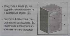
The design of the splitter is a flat box with four threaded axle boxes riveted at the corners. The top of the box is closed with a lid made of a sheet of foil fiberglass with four screws. The cover can be made of any metal, iron, brass, thus ensuring shielding of the splitter parts.
Three standard old-type television connectors are secured to the cover using M2.5 screws and nuts. The radial leads of the connectors are soldered directly to the cover. Thus, they are connected to each other and electrical contact with the screen is ensured.

The splitter parts are mounted directly on the central terminals of the television connectors.

Although more than a dozen years have passed since then, the electrical circuit diagram of the splitter has not changed and all modern television crabs and splitters are made according to the same electrical circuit. The photo shows a schematic diagram of a splitter for connecting two TVs.

To match the central outputs of connectors XW2 and XW3, a 150 Ohm resistor is installed. Transformer T1 can be made independently by winding a wire with a diameter of 0.2-0.3 mm evenly in a circle in two wires on a ferrite ring with a permeability of 600-2000 with an outer diameter of 7-10 mm. When wiring the transformer terminals, the phasing must be observed; the beginning of the windings is indicated by a dot.

I still sometimes use this splitter when I need to connect two TVs standing next to each other to compare picture quality or settings.
Although the crab has Soviet-made sockets installed, you can connect both Soviet-made plugs and modern F-connectors to it. When making a television splitter yourself, you can install modern television F-connectors instead of obsolete connectors.
How to make a TV crab from scrap material
You may have wondered and wondered what a metal box of candy is doing on a page about making your own TV crab.

Yes, this is indeed a box of lollipops, but they are no longer there, since a homemade television crab is made from it, its technical parameters are not inferior to any other industrially produced ones.

If you open the lid and look into the box, everything will immediately become clear. This is a homemade television crab, made according to the above electrical circuit diagram, but instead of connectors, the wire connections are made by soldering.
This design of the crab is completely justified; the television crab is a stationary device, it is installed once and in the future there is no need to change its installation location. And most importantly, such a TV crab can be made from any metal shoebox, sweets, or coffee. The size does not matter, the main thing is that the antenna cable mounting brackets and several radio elements fit.
To make a television crab, you need to make holes in the box at the bottom level for the television cable and in the bottom of the box for mounting brackets. If the walls of the box are thin, then it is better not to drill holes, but to push them through. First pierce it with an awl, then insert the tip of a small screwdriver into the resulting hole and press down while rotating. The hole will get larger. By changing the size of the tool, bring the diameter of the hole to the outer diameter of the television cable. The clamping strips can be made from any metal. The good thing about a pressed hole is that there are no sharp edges that can cut through the cable.

After preparing the box and clamping strips, you need to cut the television cable. It is very important not to cut the central core when removing the insulation. There is no need to remove the cable shielding, but wrap it in place with a strap.

Now you need to insert the prepared ends of the television cable into the holes of the box and secure them with clamping strips. Bend the stripped ends of the central core of the cable slightly upward.

All that remains is to mount the transformer and resistor, close the lid and the TV crab will be ready for use. If the box is of small depth, then you need to make sure that the exposed parts of the parts and the central core of the cable do not come into contact with the cover.
If it is not possible to get a ferrite ring to make a transformer for a television crab, then instead of it a splitter can be made using resistors according to the electrical circuit diagram below.

All resistors of the splitter have the same resistance, which, depending on the number of televisions connected to the antenna wire, is calculated using the given formula.
For example, to connect three TVs to a TV crab, the resistance value R will be equal to 75 Ohms × (3−1)/(3+1)=37.5 Ohms. From the standard series, the resistor with the closest nominal value is 36 Ohm, and that’s what you should take.
Below is an online calculator with which you can calculate the value of resistors for a crab, depending on the number of planned televisions or other television signal receivers for connection.
The resistor value for making crab is taken from the standard range closest to the calculated one.

The most reliable type of connection of radio components is, of course, soldering. But if it is not possible to perform the connection work in a television crab by soldering, then you can get by by twisting the leads.

For reliable contact, it is enough to tightly wrap the resistor terminal with three to five turns around the central core of the television cable. The contact will not be as reliable as with soldering, but it will be quite sufficient for stable operation of the TV crab.
You can also use a plastic box as a body for a homemade crab if you cover its body and lid from the inside with staniol (aluminum) foil. A prerequisite for this is to ensure electrical contact between the foil of the housing and the cover and with the shielding braids of the television cables.

For reliable contact of the braids, before clamping them with clamping strips, you need to wind several turns of a piece of any copper wire onto each one.
How to make a TV splitter from three resistors
For the case when there are no materials at hand, and only a knife is the only tool, I present the simplest version of a television signal splitter, with only three resistors. To your surprise, in terms of technical characteristics, if carefully executed, despite its simplicity, a homemade television signal splitter of this design will not be inferior to branded samples.

Using the technology previously described, the insulation is removed from the ends of each television cable that will be involved in the manufacture of the splitter. The cable must be cut as in the photo. I had to cut off the outer insulation completely, since I came across a Soviet RK-75 cable with very hard insulation. If the insulation is elastic, then it is better to cut it lengthwise and bend it back in order to return it to its place after soldering the resistors, as in the cutting examples when extending a television cable. The central core of each cable is tinned with solder and a resistor lead, bent into a loop, is put on it.

Now just a drop of solder from the soldering iron is enough and you get reliable contact and a strong connection. For ease of operation, the cables that will go to the TVs are laid parallel to each other and wrapped with several turns of insulating tape.

Then the shielding windings of all cables are soldered together. After this, the lead of one of the resistors is formed into a loop, the leads of the other two are threaded into it and soldered together with a drop of solder with a soldering iron.

If the outer sheath of the cable has been bent, it is returned to its place, thus isolating the resistors. In my case, I had to take a piece of insulating tube, cut it lengthwise and close the junction of the resistors. Thick insulation in this case is needed in order to ensure the minimum permissible distance between the central core of the cable, resistors and the screen. The cambric is fixed with a turn of electrical tape so that the cable braid remains open on both sides.

Next, the installation location of the TV splitter resistors is shielded. To do this, you need to wrap it around stranded copper wires turn to turn. You can simply wrap it in aluminum foil and then wrap it around a few turns of wire, as in the photo. The main thing here is that the screen has electrical contact with the shielding braid of the television cable.

Finally, the splitter is covered with several layers of electrical tape to give it an aesthetic appearance. To impart rigidity and strength, it is advisable to place a metal strip along the television cable before insulation, but it can be made of any material.

The end result was a splitter as good as any crab. The disadvantage of this design is the inability to quickly switch the antenna cable.
Resistor values, depending on the number of connected TVs, are calculated using the formula given on the page above. Instead of resistors, it is better to use a transformer, then there will be less loss of the television signal.
This is wrong, but in a hopeless situation it is permissible to connect the central core of the antenna cable with cables going to the TVs directly to each other, without resistors or a transformer. Since the cables will not be matched in terms of characteristic impedance, you will have to pay for such a splitter by losing the quality of watching TV shows. There may be interference from the local oscillator of a TV connected in parallel (only when both TVs are working simultaneously) and a small fringing in the image. This connection is safe for both televisions and cable equipment or a television antenna.
Having two or more TVs in a house or apartment has long ceased to be considered a luxury. Therefore, if there is not one TV in the room, but several, you should think about purchasing an antenna splitter.
After all, for a full and uninterrupted broadcast transmission on all TVs located in the same home, you need to correctly select and connect a splitter - an antenna splitter (divider), which allows you to connect one cable simultaneously to several TVs without losing signal quality.
Buying a divider is easy Moreover, modern manufacturers offer a huge selection of splitters depending on the presence of an amplifier, the frequency of received channels, the number of TVs in the house and the thickness of the existing cable. However, when choosing this device, you need to be guided not only by these parameters, but also by the types of antenna splitters, as well as the splitter’s ability to pass the signal in the opposite direction.
Well, in order not to get completely confused in the choice, first you should decide on the main types of these devices.
Types of splitters and their main characteristics
All splitters are very similar to each other– they have a body made of metal and several connectors for connecting a cable. But, despite the similarity, each splitter model differs depending on its functional purpose:
- for 2 outputs;
- for 3 outputs;
- for 4 outputs;
- for 6 outputs;
- and a splitter for 8 outputs.
Each television splitter, regardless of the number of outputs it is intended for, has a high bandwidth F connector, both for general and satellite TV. Moreover, depending on the device model, the surface of the outputs may have a silver or gold coating, due to which the level of signal strength loss is significantly reduced and the broadcast quality is improved.
The best device options are splitters that have an amplifier, high resistance and high frequency. Regardless of the antenna splitter model, all devices operate at a standard frequency - 5-1000 MHz for terrestrial TV, and 5-2500 MHz for satellite TV.
In addition, on the body of each device model The connectors are always marked:
- IN – input for an antenna entering the room;
- OUT – output for the cable that connects the splitter to each TV in the room.
If you plan to purchase a splitter to connect a large number of TVs, you need to purchase an amplifier in advance to maintain image quality.
What parameters should you be guided by when choosing a splitter?
Before you buy the device, You must first understand the basic parameters of the splitter.

Thus, in order for every TV in the house to broadcast all channels in a high-quality manner, it is necessary, first of all, to decide on the parameters of the splitter.
Splitter connection options
Currently There are several main options for connecting the device:

Device connection diagram
In order for every TV in the house to transmit high-quality broadcasts, you need to correctly connect the antenna cable to the splitter. Regarding the installation diagram of the device, then it is very simple and does not require any special knowledge of electronics.

If there are unused outputs left in the device, it is better to immediately plug them with a resistor. This approach helps absorb excess stress.
The best characteristics of splitters depending on the number of connected TVs
The most popular today are the following dividers:
- for 2 outputs with an isolation of 29 dB with a through loss of 3.6 dB;
- for 3 outputs with isolation 28 dB with pass loss of 5.8 dB;
- for 4 outputs with 32 dB isolation with a pass loss of 7.2 dB.
In this case, the separation coefficient regarding power is usually the same, and in rare cases it is unequal.
Moscow: where to buy and price of dividers
The price of this device will directly depend on its parameters and the manufacturer. You can order the device online through any online store specializing in the sale of the relevant type of goods. Approximate cost of splitters in Moscow is given below.

- Device for 4 outputs with an F connector with a frequency from 5 to 2500 MHz, manufacturer Rexant - price from 300 rubles.
- Device for 6 outputs with an F connector with a frequency from 5 to 1000 MHz, manufacturer Rexant - price from 330 rubles.
- Device for 8 outputs with an F connector with a frequency from 5 to 2500 MHz, manufacturer Rexant - price from 520 rubles.