Self-made woodworking machine. DIY wood lathe: tips for making and using How to choose an electric motor for wood processing
We will tell you how to make relatively simple woodworking machines and accessories for them with our own hands, using the available tools and materials, as well as about the basic operations for the technical processing of wood.
As parting words, I would like to give you some advice and wishes: if you embark on the path of technical creativity, arm yourself with patience and perseverance; measure your desires against the available possibilities; use simple techniques, tools and materials available; do not give up at the first setbacks. Success will definitely come to you!
Latest publications on the site
ELECTRIC MOTORS
The heart of the machine's electric drive is deservedly the electric motor (ED). The number of their series, types, specific performances is difficult to account for, and even more so to describe. But, I think, this information is useless for a home craftsman: after all, he has access to a very limited range of ED, usually installed in household appliances and machines. They also arouse his keen interest. He most often uses them in his designs. We will talk about them.
Since DC motors are of limited use in everyday life, with the exception of toy drive mechanisms, portable tape recorders and other small-sized devices, we will not dwell on them. We only note that DC motors of appropriate power are used in vehicles, for example, on airplanes, ships, etc., where they can be powered from the on-board network, as well as in various industrial equipment due to their high efficiency, stepless speed control and others. positive qualities. Such EDs are connected to the AC mains through special rectifiers.
But collector AC motors, despite a rather complex device, are very widely used in everyday life, since they have many positive qualities.
The excitation winding of such an EM is switched on in series with the armature winding, due to which, when the direction of the current in the network changes, it simultaneously changes
The direction of the current in the armature and the polarity of the poles. In this case, the direction of the torque is retained.
The electric motor rotation frequency does not depend on the frequency of the current in the network and can be very significant. This circumstance allows the use of collector motors in vacuum cleaners, fans and other devices, where a high rotation frequency of the working body is dictated by necessity. These motors retain the main characteristics inherent in collector DC electric motors, and are used where a large starting torque is needed (floor polishers, meat grinders, food processors, etc.) Due to the high rotational speed, such an engine is characterized by a high power density per unit mass and is lightweight. which is very important for handheld electrified tools and other portable devices. The advantage of these motors is their ability to withstand short-term overloads. Their work is not disturbed even with significant voltage fluctuations in the supply network. The current strength at the start of such EMs, as a rule, does not exceed four times the nominal value, so they operate stably in the mode of frequent starts and stops.
The collector EM can be made for low supply voltage and for the voltage of the lighting network. It can operate on direct and alternating current, changing only the nominal data depending on the type of current. In order for these data to be approximately the same, the EM excitation winding is performed with an additional terminal. When operating on direct current, all turns of these coils are turned on, and with alternating current, only a part of them. Such an engine is called universal.
The advantage of the collector EM is that it easily lends itself to smooth regulation of the rotational speed in the widest range, as well as reversal (change in the direction of rotation). To do this, it is enough only to change the direction of the current in the armature winding or the excitation winding, changing their ends in places.
Unfortunately, single-phase collector motors are not without their weak points. They are complex and expensive to manufacture, require qualified maintenance,
constant care of brushes and collectors, they need special filters to suppress interference with radio reception. To give a more specific idea of collector ED, let us turn to the motors of the LPC type, which are installed in many hand-held electric machines (saws, planers, drills, jigsaws, etc.) and are structurally connected with them, i.e., they are built-in.
They are double insulated, which greatly increases the safety of working with them. Their power is 120–1150 W, the rotation frequency of the armature is 12000–18000 min1. They are directly powered from AC and DC mains without the need for bulky transformers or frequency converters.
The stator of the LPC motor, mounted in a plastic case, consists of a package of steel plates, in the cutouts of which two coils of electromagnets are installed, passing through which an electric current creates a constant magnetic flux.
The rotor consists of a steel package, in the grooves of which the winding is laid. Its conclusions are connected to the collector. The shaft, with a rotor, a collector and a fan mounted on it, rotates on two ball bearings. One of them is mounted in the socket of the rear wall of the case, and the other in the socket of the intermediate shield.
The fan serves to cool the engine during operation. Air is sucked in through the inlet windows in the casing, cools the stator winding and is pushed out through the windows of the intermediate shield into the atmosphere.
The brushes are placed in a special holder and pressed against the collector by springs. Electricity is supplied to the brushes through two wires connected to a two-pole switch.
The radio interference suppression filter is mounted on the rear wall of the engine housing and is covered with a casing. As already mentioned, collector motors can be used in the drive of light milling, drilling, sharpening, turning machines and in other home-made structures. They work especially successfully with power devices that allow you to regulate their rotational speed, as well as reduce the temperature of the case.
This is most easily achieved using an adjustable laboratory autotransformer (LATRa). The motor can also be connected to the network through an autotransformer, which makes it possible to obtain several fixed output voltages. Unfortunately, such devices are not available for sale. But if you wish, you can make the autotransformer yourself. To do this, select a magnetic core with a cross section of 16–20 cm2 (for example, ШЛ 32 x 50), wind a winding of 400 turns of wire PEV2 1.5mm. Make bends from 230, 270 and 320 turns. Connect the output from the beginning of the winding to one terminal, and all the others to the other terminals located around the first. By closing the beginning of the winding alternately with its other terminals, it is possible to obtain a number of AC voltages required to power the motor.
Thyristor voltage regulators are even more convenient, allowing smooth regulation of the electric motor rotation frequency. Similar devices are available commercially. If necessary, you can make such a regulator yourself. A lot of their schemes were published in the magazine "Radio", on the pages of the article "Mass Radio Library" and other similar publications. For the most part, such devices allow you to regulate the voltage on an active load in the range from 0 to 220 V. The load power also varies in a wide range from several watts to 1.5 kW or more. With their help, it is possible to obtain direct current and supply them with universal collector motors, as well as DC motors. To do this, it is required to include an electrolytic capacitor of the appropriate capacity and the required operating voltage into the rectifier circuit of the thyristor voltage regulator and connect the leads to it to the load.
In recent years, they began to produce hand-held drilling machines (drills) with small-sized electronic control units. They can also be used to power stand-alone collector motors of the corresponding power. Collector EDs built into self-made machines (especially closed type), it is desirable to intensively cool. Very convenient for this, for example, small-sized fans from personal computers.
Inexperienced readers should be cautioned against using in most homemade woodworking machines, with the exception of milling, high-speed motors without appropriate gearboxes and other speed controllers.
Another tip: in cases where you need to free both hands for work and, at the same time, often turn on and off a machine that uses a commutator motor, there is no better assistant than a foot switch. It consists of a wooden block of the base, inside which a push-button switch of any type is reinforced. The pedal is folded out of sheet metal. They fasten it to the base with two screws, which simultaneously serve as the axis of rotation. So that the pedal can independently occupy the upper position, it is spring-loaded (a piece of foam rubber, a rubber tube, an elastic metal plate or a cylindrical spring is placed under it). From the switch, wires with a socket and a plug are brought out to the outside for connection to the electrical network and the engine. The robust design is also obtained from the mains one-gang switch. It must be screwed to a wooden base, and an elastic material should be placed under the key.
Single-phase induction motors are widely used in various household appliances. They are structurally different from collector ones and have tangible advantages over them: they do not interfere with radio reception, are much simpler in design, which means they are cheap and reliable, and do not require large operating costs. The principle of operation of such an EM is that the EMF in the rotor winding is induced by an alternating magnetic field. Therefore, there is no need to supply current from an energy source to it, and therefore there is no need for sliding contacts in the form of brushes and a collector. Moreover, since the rotor winding is not connected to the power source, it does not need to be isolated from the rotor core itself. If you hammer copper or aluminum rods into its grooves, then the current will go through them, and not along the steel sheets from which the core is assembled, since they have a much lower electrical resistance.
However, when connected directly to the network, such a motor will not rotate due to the absence of a rotating magnetic field in it. Therefore, numerous types of self-descending EDs have been developed.
The most widespread are single-phase asynchronous motors with starting windings. These windings are not concentrated in the form of coils, as in DC motors, but are evenly distributed in the stator slots. The working winding remains connected to the network for the entire duration of the operation of the electric motor, and the starting winding is turned on only for the time the rotor starts to move from its place and turns off when the engine picks up the required number of revolutions. In the starting winding circuit there is a starting element, most often in the form of an active resistance or capacitor. The motor can be easily reversed by swapping the output ends of the working or starting winding.
There are motors in which the starting resistance is enclosed in the starting winding itself. These include single-phase ED of the AOLB series, which have satisfactory starting and operating characteristics.
ED with starting capacitors have higher starting properties. These include, in particular, engines of the DOLG series. In an EM with a starting winding, after it is turned off, 1/3 of the stator slots remain unused, therefore it has a reduced useful power. To increase it, they began to use motors in which the starting winding always remains connected to the network through a capacitor. Such an ED is called capacitor, and its starting winding is called auxiliary. This motor has many positive operating properties: high shaft power, high efficiency and increased power factor. But, unfortunately, it has rather low starting characteristics. To improve them, at the time of starting the electric motor, they began to include an additional so-called starting capacitor in parallel with the working capacitor. This engine was designated AOLD.
Later, they began to produce capacitor EDs of the ABE series, which have better performance characteristics than their predecessors.
Currently, single-phase capacitor motors are produced with increased power, up to 1.3 kW. They, in particular, are widely used in household woodworking machines manufactured by industry.
Many motors used in household electrical appliances can be successfully used to drive various home-made machine tools. As a rule, they should be connected to a network with the same starting and protective equipment with which they were installed in household machines.
To give readers an idea of the electrical equipment of a modern desktop woodworking machine, in which a capacitor motor is used, we will give its electrical schematic diagram (Fig. 62).
The motor is protected from overloads by the KK1 thermal relay, which breaks the starting network of the KM1 starter. Restarting is possible only after 15–20 s, that is, after the return of the thermal protection elements of the KK1 relay to its original position. An increase in the starting torque when starting the EM occurs due to the connection of C, parallel to C2. Frequent starts it is unacceptable, since it will be disconnected by a thermal relay. The electrical circuit provides zero protection, which is carried out by opening the block contacts of the KM1 starter when the voltage disappears in the self-supply circuit of the magnetic starter and in the circuit of the starting winding of the motor.
Until now, we have been talking about single-phase electric motors. This is natural, since single-phase current has become widespread in our country among individual consumers. However, with the emergence of small private enterprises in the city and in the countryside, a huge number of horticultural associations, the situation has changed dramatically in recent years. For the intensification of labor in such farms, the need arose for more powerful electrified machines and tools with three-phase motors, in a more ramified network for their power supply.
Home craftsmen, of course, do not stand aside from these changes, many of them are already widely using them. This is due to the fact that three-phase asynchronous squirrel-cage motors have many indisputable advantages: simplicity, reliability, compactness, low cost, economical maintenance, the ability to maintain an almost constant speed when the load changes. Their power is essentially limited only by the parameters of the wiring. They do not require bulky and expensive capacitors. True, such engines have their weaknesses: low overload capacity, reduced reliability when 
work with frequent starts and stops, etc. And nevertheless, these disadvantages do not detract from the advantages of three-phase motors.
How does such an engine work? Its stator consists of a package of electrical steel sheets, in the grooves of which a three-phase winding is laid. The rotor is also assembled from a package of steel sheets. It is wound with aluminum rods that run in its grooves and are short-circuited at the ends in rings. Hence, the engine was named short-circuited. The rotor is mounted on the shaft together with the fan. The shaft rotates on two ball bearings. The stator windings have six ends and can be interconnected according to the established scheme by a star or a delta (Fig. 63). In the first case, the beginnings or ends of all three phases converge at one point, and the remaining three outputs are connected to a three-phase network. In the second option, the end of the first phase is connected with the beginning of the second, the end of the second - with the beginning of the third, and the end of the third -
with the beginning of the first. A three-phase network is connected to the points of their connection.
Typically, the winding terminal clamps are positioned on the motor block in a specific order. In this case, a star connection is achieved with a horizontal, and a triangle - with a vertical arrangement of jumpers (Fig. 63). The option for connecting the ends of the stator windings is chosen depending on the voltage in the network (most often it is 220 or 380 V). If the engine must operate from a 220 V mains, then the output ends of the windings are connected with a triangle, and from a 380 V mains - with a star. Reversal of the three-phase EM occurs if you swap any two phase wires. Electric current to a three-phase motor is usually supplied with a four-core cable, one of the cores of which is used to connect to the EM body.
Asynchronous three-phase motors are included in a three-phase network most often according to the generally accepted scheme 
(fig. 64). In this case, magnetic starters, circuit breakers and fuses are used as protective and starting equipment.
However, some home craftsmen, due to the lack of such equipment, connect the engine directly to the network. At the risk of incapacitating him, they still get out of the situation. It is possible to do this in the presence of a fuse and under the condition of constant monitoring of the operating EM in order to immediately turn it off in case of a smell of overheated insulation of the windings or the appearance of unusual sounds emitted by the motor.
In practice, there are often cases when it is required to use a three-phase motor in a single-phase network. And so they do, despite the fact that in this case he does not have a starting moment and he cannot start on his own. Therefore, they go to various "tricks". For example, it is known that if the rotor of an engine is moved from its place, then it begins to rotate. This is how the ED is sometimes launched, that is, by hand or with the help of a rope wound on a shaft. Unfortunately, this method is far from the best: it is very dangerous, and the ED power in this case is not high, amounting to only 50% or less than the nominal one. In addition, this option for starting ED is generally unacceptable for powerful drives.
A three-phase motor in single-phase connection is incomparably better to use with capacitors, since this increases its power factor, which can acquire values almost equal to unity. However, it should be borne in mind that the capacitances of the starting and working capacitors at a certain mains voltage and the adopted EM switching scheme depend on its power. With an increase, its capacitances also increase, reaching a reasonable limit when the use of capacitors, due to the increase in their cost and weight, becomes economically unprofitable. The maximum power of a capacitor motor is considered to be a nominal power of 1.5 kW, indicated on its plate. The basic electrical circuits of a capacitor motor with three windings on the stator are shown in Fig. 65. 
As in the case of a three-phase connection, the stator windings can be connected in a star (Fig. 65 a) or a triangle (Fig. 65 b). The mains voltage is supplied to two motor terminals corresponding to the beginning of two phases. Capacitors 1 and 2 are switched on between one of them and the output corresponding to the beginning of the third phase. The latter, as soon as the EM picks up speed, turns off, and only capacitor 1 remains in the circuit. In these circuits, three combinations of the formation of input (network) outputs are possible: C1 - C2; C1 - SZ; SZ - C2.
Switching one of them to another leads to a change in the rotation of the rotor (reversal).
In two other variants of switching circuits (Fig. 65 c, d), two windings are formed from three phases of the original motor. One of them is made up of two phases connected in series. In the circuit of the other winding there are working and starting capacitors.
The correct choice of working capacity is very important. It is considered optimal if the phase currents and voltages under load become practically nominal. This capacity is proportional to the motor power (rated current) and inversely proportional to the voltage. With regard to the considered schemes for switching on a capacitor EM for a network frequency of 50 Hz, the capacity of a working capacitor can be approximately determined by the following relations:
for the circuit in Fig. 65 a - Sr nom ~ 2800 (J HOM / U); for the circuit in Fig. 65 b - Sr nom ~ 4800 (Jhom / U); for the circuit in Fig. 65 V - Wed nom ~ 1600 (JH0M / U); for the circuit in Fig. 65 g - C number ~ 2740 (JHOM / U);
where J ty - rated current, A; U - mains voltage, V;
With a known engine power, the current consumed by it can be determined by the expression:
J = P / (1.73 Uncos (p);
where Р - engine power (W); U - network voltage (B); cos f - power factor; c - efficiency, indicated on its dashboard.
With the most common connection of motor windings with a triangle in a 220 V network, the working capacity (in microns) can be found by the formula:
Ср = 66 Рн, where Р - EM rated power, kW.
Sometimes for people not experienced in electrical engineering, it is recommended to carry out a simplified calculation when choosing the capacity of a working capacitor: for every 100 W of engine power, set about 7 microns of capacitor capacitance. With a certain assumption, one can agree with such a mnemonic rule.
When determining the starting capacity, one proceeds primarily from the requirement to create the required starting torque. If, according to the operating conditions of the electric drive, the engine is started without load, then this capacity is often taken equal to the working one. When starting under load, it is usually calculated by the expressions: Cn «(2 ... 3) Cp; Cn = 132 Rn or determined empirically.
Equally important is the choice of capacitors according to their operating voltage, and the latter can be determined by using the following ratios:
for the circuit in Fig. 65 a and b - UK ~ 1.15 U;
for the circuit in Fig. 65 in - U „„ ~ 2,2 U;
K. p
for the circuit in Fig. 65 g - UK ~ 1.3 U; where UK is the rated voltage of the capacitor.
It is considered to be selected correctly if its rated AC voltage is equal to the calculated one or slightly more than it. From the above ratios it follows that when the engine is turned on according to the circuit (Fig. 65 c), the operating voltage of the capacitors should be almost twice as high as in the other circuits. This feature must be taken into account in practice.
What types of capacitors are recommended for use as operating and starting capacitors?
For such purposes, paper and metal-paper capacitors are most often used: KBG - MN; BGT, MBGO, MBGP, MBGCH. You need to know that on all these capacitors, except for MBGCH, the rated voltage for direct current is indicated, and their reliable operation with alternating current is achieved by choosing a two-fold or more voltage margin. Capacitors only
MBGCH are designed to work in alternating current circuits. Therefore, they are selected according to the voltage closest to or greater than the phase voltage.
Capacitors built into network luminaires with fluorescent lamps can also be used along with MBGCH capacitors.
All of these types of capacitors are used as starting capacitors. Often, in order to reduce the cost, volume and mass of the container, electrolytic capacitors of the K5019 type are used, or, what is better, EP, specially designed for operation in alternating current circuits, and in extreme cases - KE2N; K503, etc. with a margin of rated voltage. All electrolytic capacitors can be connected to the network for a maximum of 3 s. It is unacceptable to use them as workers, since in AC circuits they quickly heat up, fail, even exploding. It must be remembered that after disconnecting from the network, starting capacitors retain voltage at their terminals for a long time, creating a danger of electric shock if touched. This danger is the higher, the higher the capacity and voltage in the network. When repairing and debugging the engine, the capacitor should be discharged after each shutdown, or better - soldered in parallel with it a resistor with a resistance of 68–75 kOhm and a power of 2 W.
A few words about the installation of capacitors. It is desirable to place them in a durable, dust-proof enclosure made of dielectric material and fasten them to the base with metal strips placed in PVC tubes. Capacitors are usually connected to each other with tin-plated wire, passed through the holes of the output tabs. In this case, the places of the rations are not destroyed due to vibration of the machine. The conclusions are made with multi-colored wires.
Some readers, of course, are interested in the question: which of the considered schemes for connecting a three-phase motor to a single-phase network is preferable? Before answering it, let’s first note the characteristic features of each of them.
So, the circuit shown in Fig. 65 a, differs in a relatively small value of the starting torque and voltage across the capacitor. A small starting torque is also inherent in the circuit in Fig. 65 b. The advantages of the circuits in Fig. 65 c and d - the ability to achieve a significant starting torque and better use of engine power.
It seems that everything is simple, stop your choice on the scheme that you like. But it turns out that you cannot do that arbitrarily. The connection diagram is determined taking into account the mains voltage and the voltage data of the motor. It will be selected correctly if any of the stator windings at rated load is energized equal to or close to rated voltage. In other words, the phase voltage of a three-phase motor should be preserved when it is connected to a single-phase network.
It is known that many three-phase electric motors are designed for two line voltages, for example 127/220 V or 220/380 V. At a lower voltage of the electrical network, their winding is connected into a triangle, and with a higher voltage, into a star. It follows from this that if the supply network has a voltage of 220 V, then the ED, made for a voltage of 220/380 V, is switched on according to the diagram in Fig. 65 in; the motor for voltage 127/220 V in this case can be switched on according to the diagram in fig. 65 a. Only in the 127 V network is it included according to the diagram in Fig. 65 b.
Many older motors have six leads on the clamps. Nowadays, there are more and more EDs, in which the stator windings are connected by a star or a triangle tightly and only three terminals are brought out to the terminal block (the beginning of the phases). In the latter case, you can disassemble the ED, disconnect the phase-to-phase connections and draw three additional conclusions. Sometimes they act differently: a motor designed for a voltage of 220 V with three leads and a stator winding connected to a star is connected to a single-phase network with a voltage of 220 V according to the diagram in Fig. 65 a, and the same ED with a winding connected in a triangle, according to the diagram in Fig. 65 b. Considering that when starting a three-phase motor, the starting current exceeds the rated one by 4-8 times, in some cases they produce
reducing it by switching the stator windings from delta to star. This is done using a special switch.
One of the features of the operation of a motor in a single-phase network is overheating of its windings both during prolonged overload and during prolonged underloading. This is explained by the fact that in the first case, the originally calculated working capacity turns out to be too small, and in the second - too large. Therefore, they try to avoid such cases, achieving optimal engine operation.
One of the ways to improve the performance properties of a capacitor motor is to use an automatic variable capacitance. Unfortunately, such devices are rather complicated, expensive, and therefore difficult to use in everyday life. The use of a working capacity for these purposes, consisting of several sections of capacitors connected to the motor using conventional toggle switches, does not justify itself either: it is enough to forget to switch them in time, taking into account the expected load on the motor, as it will be disabled as a result of overheating of the windings. In the circuits for switching on a capacitor motor, conventional control and protection equipment is used: switches, buttons, relays, fuses, etc. 220 V, 50 Hz (Fig. 66).
The engine is started and stopped using the KV relay, which controls the SB2 (Start) and SB1 (Stop) buttons. At start-up, the KV relay turns on and becomes self-powered, connecting the EM with its contacts to the network and providing zero protection, that is, turning it off in the absence of voltage in the network. Motor overload protection is provided by relay A, which breaks the starting circuit, disconnecting the KV relay. Restarting is possible only after the thermal protection elements of relay A return to their original position.
An increase in the starting torque of the EM occurs due to the connection of the capacitor C1 by the contacts of the relay A 
parallel to the working C2. After the EM acceleration, the capacitor C1 is turned off. The fuse FU serves as short-circuit protection. Reversing of the engine is carried out using the SA switch, which, in the middle position, ensures that the EM is disconnected from the network. As is clear from what has been said, a wide variety of electric motors are used in domestic conditions. In order not to "get lost" in them, to be able to choose the right one, taking into account a specific electric drive, special knowledge is required.
More successfully navigate in all the variety of electrical machines help, in particular, information on the marking of the terminals of their windings. For example, in DC motors, the ends of the windings brought out to the outside are marked with letters: I - armature winding, K - compensation, D - additional poles, C - series excitation, W - parallel excitation, H - independent excitation, P - starting, U - equalizing winding ... Numbers are added to the letter designations: 1 - the beginning of the winding, 2 - its end. In most cases, the windings of alternating current machines are located on the stator, therefore their terminals are designated with the letter C. The beginnings of the 1st, 2nd and 3rd phases of a three-phase winding are labeled C1, C2, SZ, respectively, and the ends of these phases with an open circuit are C4, C5, Sat. The outputs of the phases of the windings of multi-speed asynchronous EMs are additionally designated in front with numbers indicating the number of winding poles, for example 4С1, 4С2, 4СЗ.
The conclusions of the stator windings of single-phase asynchronous machines are marked with the letter C, and the excitation windings with the letter I.
For asynchronous single-phase motors, this marking looks like this: C1 is the beginning of the main and B1 is the beginning of the auxiliary windings, and C2 and B2 are their ends, respectively. Lead markings are applied to the terminal block next to them or directly to the lead wires.
In small cars, where, due to lack of space, letters and numbers are difficult to mark, the lead ends are made multi-colored. So, in three-phase asynchronous ED, the beginning of the 1st, 2nd, and 3rd phases are shown in yellow, green and red, respectively. The ends of the phases with six leads have the same colors, but with the addition of black. The zero point when the phases are connected to a star is black. The terminals of the delta-connected winding are of the same color as the beginning of the phases in the open circuit.
In single-phase asynchronous machines, the beginnings of the windings are denoted: the main - in red, the auxiliary - in blue, and their ends - in the same color as the beginnings, but with the addition of black. With three pins, the common point is indicated in black.
In small DC and AC collector machines, the beginning of the windings are marked with the following colors: armatures - white, parallel excitation - green. At their ends, black is added to the specified colors.
As for the choice of a motor for a specific drive of the machine tool, this is not as simple as it might seem at first glance. Ideally, the engine should meet the requirements for it in literally all parameters. Of course, it is almost impossible to achieve such an ideal, but you need to strive for it. Before we talk about this, we will give a few more background information.
It is known that ED, like any other product, is produced in accordance with the established requirements. For example, their nominal powers, ranging from several watts to hundreds of kilowatts, have a strict gradation, the so-called series. This series for low-power electric machines looks like this: 0.06; 0.09; 0.12; 0.18; 0.25; 0.37; 0.55; 0.75; 1.1; 1.5; 2.2; 3.0 kW. And a number of synchronous rotation frequencies of motors at a mains frequency of 50 Hz has the following values: 500; 750; 1000; 1500 and 3000 mins1. Three-phase asynchronous motors are currently produced at rated voltages and stator winding connection diagrams according to the data contained in table. 9.
When choosing a motor, first of all, take into account that it must ensure the performance of the necessary operations on the machine at the lowest cost of electrical energy.
Table 9 Therefore, despite the known direct dependence of the efficiency of the engine on its power, the use of an oversized electric motor is considered unjustified. In the process of operation, being underloaded, it will be used with low efficiency. On the other hand, ED of insufficient power will not provide the required productivity of the machine; in addition, it will overload and overheat quickly. Thus, when choosing the DE in terms of power, one should adhere to the golden mean and determine its value with the greatest possible accuracy.
As for the voltage for which the engine should be designed, then I think everything is clear: the local power grid dictates its own conditions. A single-phase network, as a rule, has a voltage of 220 V, and a three-phase network - 220/380 V. This means that the motors must correspond to it. In this case, the still encountered single-phase EMs for a voltage of 127 V can be powered through transformers and autotransformers, and three-phase ones for 127/220 V can be connected to the network according to the diagrams given earlier.
It is also important that the speed of the engine rotor is as close as possible to the speed of the working element with which it is connected. In this case, preference should be given to high-speed electric motors, since they usually have better characteristics, smaller dimensions and weight, and lower cost.
Considering that many woodworking operations are performed with cutting tool speeds of the order of 3000 min1, the rotor of the engine must rotate at the same frequency. At the same time, slow-moving EDs do not justify themselves. The fact is that at low speeds circular saws, milling cutters, planing knives cut wood poorly and with low productivity. An increase in their revolutions is associated with such a reduction in drive mechanisms (pulleys, belts), in which a gain in speed inevitably leads to a loss in oil. As a result, the engine starts poorly and stalls under light load. With regard to the main operations performed on machine tools, it is possible to recommend such speeds of rotation of the working bodies, which are indicated in table. 10.
240
Table 10 Rotational speed of the working bodies for various operations An important characteristic of the engine is its starting torque. It should always be greater than the starting point of the machine spindle, and the acceleration time of the machine did not exceed 15–17 s.
Naturally, when they are looking for the right engine, they pay attention to its design, mounting method, dimensions, possibility of placement in the machine drive, etc. Motors are available on feet, with feet and a flange shield, or only with a flange. In each case, they specify how best to secure it. The fastening must be reliable, sufficiently rigid and, at the same time, allow adjustment of the EM position, free access to it during maintenance and repair. The selected motor is checked by the heating of its housing so that the maximum temperature rise of the stator winding over the ambient temperature does not exceed the established limits. Otherwise, they try to improve its cooling; if necessary, use an additional fan. The outer surface temperature of most engines should not exceed 65 ° C. In practice, it is determined by the palm attached to its body: when overheated, the hand cannot withstand such a touch.
Based on the foregoing, we can recommend for the Universal1 machine a single-phase asynchronous motor with a capacitor start with a power of 1.1 kW and a frequency
rotor rotation 3000 min1, and for a three-phase network - a three-phase SP with the same data. In desktop small-sized designs, it is permissible to use low-power motors of various types and characteristics.
The site for the woodworking machine submitted to the readers of the site I independently designed, made it with my own hands and now I successfully use it when building a house on my site. I am convinced how successful the design has turned out: compact, technological, quite, I think, suitable for its "replication". The machine is so simple that super-detailed detailing is hardly required for its manufacture. All attachment points are freely accessible here. So, if desired, the structure can be easily disassembled and, having transported in the trunk of a car, assembled in a new place in thirty minutes.
Woodworking machine drawings


The proposed version of the universal woodworking machine - with supporting elements made of steel angle and sheet steel. Although I know: it will not be difficult for an experienced home-builder to find a suitable replacement for these materials from what is at hand. Of course, with the maximum use of technical solutions that ensure compactness, manufacturability of assembly and disassembly.
Take at least welded assemblies and parts. There are not many of them. First of all, it is a support-base made of steel angle 50x50 mm. Then comes the frame for the installation of the L-shaped racks of the table and bearing assemblies of the driven shaft with the working bodies of the machine. It is made of steel angle 60x60 mm. Welding work will also be required when rigidly fixing the bushings of the L-shaped struts to the table top, making a limit ruler and a special rotary platform for the electric motor.
Special mention should be made of the latter. It is welded from pieces of steel angle 40x40 mm and a bar, at the ends of which an internal thread M12 is cut. The bar serves as the pivot axis of the platform, is inserted between the posts and fixed on both sides with M12 bolts. The AIR100B4UZ three-phase asynchronous motor with a 100-mm double-strand pulley is installed on the platform using four bolts with Grover nuts and washers.
The tension in the V-belt transmission is carried out by twisting the lamb on the bar passing through the hole in the platform, followed by locking.
Support base, frame and four uprights made of 40x40mm steel angle, fastened together with M20 bolts, form the frame. To it are screwed chutes made of sheet aluminum for sawdust and shavings, other units and parts, including the equipment for starting and controlling the electric motor.
The table top consists of two identical 6 mm steel plates, held together by side members using M12 countersunk screws and locknuts. As already noted, four bushings are welded to the bottom surface of the cover, in which the L-shaped struts can rotate. As for the limit ruler, it is attached to the rails using compound clamps and M8 screws.
A few words about the engine. Since a three-phase AIR100B4UZ (3 kW, 1410 rpm) was used in the machine, it was necessary to introduce starting and operating phase-shifting capacitors to connect it to a single-phase network. And for the most effective use - provide for the connection of the windings either "star" or "triangle". The first of the named modes (with the symbol "Y") is recommended for use when sawing and planing with a reduced load (when the boards are not too thick). The "Start" button is pressed here if BA1 is disabled, BA2 is on, and the BAZ is in the "U" position. In this case, the magnetic starter will work and, blocking the BV1, will provide a reliable voltage supply to the motor windings.
Mode with the symbol "D" is work with increased power. They switch to it after the electric motor, having thoroughly accelerated, picks up the required speed in the "U" mode. Then boldly increase the capacity of the phase-shifting capacitor, additionally connecting another 100 μF with the help of BA1. And only then, avoiding strong starting currents, they switch the windings to the "triangle", moving the BAZ to the "D" position.
It is easy to stop the engine in any of the modes. To do this, just click on the "Stop" button. Then the supply voltage to the coil winding of the magnetic starter will immediately stop, and it will de-energize the electric motor.
As for the BA4 "Reverse" switch, as practice has shown, it is not necessary to install it. And the required direction of rotation is achieved in this case during commissioning by "flipping the ends" of one of the windings.
And one more remark regarding the peculiarities of the functioning of the considered scheme. After stopping the motor, both capacitors must be discharged. To do this, you just need to ... turn on BA1 and BA2.
It's time to consider the features of the operation of the machine itself as a whole. It is better to do this by referring to the illustrations.
First of all, adjustment of the cutting height, as well as the thickness of the chip removal. The required results are achieved here ... by turning the nuts. Special, adjusting, with subsequent fixation with the lower nut.
Changing the tilt of the table (when sawing at an angle other than straight) is carried out by simply raising (or lowering) the stands (on the opposite side of the saw blade) to the required height. Optimum shaft speeds (1500 rpm for sawing and about 3500 rpm for planing the starting material) are achieved by appropriately selecting the diameters of the drive and driven pulleys.
Other possibilities of the machine? They are in direct proportion to which tool is on the working shaft. For example, using various cutters, you can successfully select grooves, quarters. Replacing the saw blade with a cut-off wheel, we get a reliable mechanical metal cutter. And with the installation of emery, a tool sharpening machine.
But all this requires accuracy. And, of course, the strictest, strict observance of safety rules. In particular, when installing the shaft on the frame of the bed, it must be fixed rigidly, without skewing. After tightening the bolts on one support first, make sure that the other is not lifted over the frame and is not overly pressed against it. Then you need to use the same precaution to tighten the bolts on the second support. Eliminate the misalignment immediately by placing metal spacers under the supports. The bearings must be filled with refractory grease. Make sure that sawdust and shavings never get into them.
The plane should be treated with equal care. The blades of this implement must be bolted securely. It is worth recalling that when the plane is not used, it must be closed with a special metal cover (not shown in the figure).
In order to avoid any surprises, the nuts for fastening the "circular" must certainly be with Grover washers, and the rest of the threaded connections will not interfere with proper tightening. Before working on the machine, check how well everything is fixed. Ensure the reliability of the V-belt transmission by turning the shaft itself several times behind the drive belt. The latter should rotate easily, without jamming. And only then can you start working.
All DIYers who make machines and devices at home with their own hands, sooner or later face the question of which power unit to install to drive their machine. It would seem that he picked up the right power, pulleys or a gearbox went to the required speed and that's it, there is no problem... But in reality, not everything is so simple. The correct choice of the engine will determine how the machine will work, whether it will delight you with its work or will start to cause problems.
In this article I will try to touch on some of the nuances and parameters of electric motors that are most often asked about, as well as tell about little-known facts.
First of all - asynchronous motors. These are the most common and most used DIY drives. Due to its advantages, including long-term operation, ease of maintenance, low noise, a large selection of configurations, mounting methods, parameters and much more. Their shortcomings fade into the background and are forgotten. And this is not correct. The main disadvantage of such motors is that they are designed for a three-phase network. The fact that there are single-phase capacitor ones is rather a trick that allows you to at least somehow use asynchronous devices in everyday life. The only exceptions are short-circuited loop motor ... But they have very low shaft torque and are used in low-power applications such as fans and small pumps.
Other asynchronous motors connected to a single-phase network will have a weak torque on the shaft, hence a difficult start under load and less power compared to a motor with the same parameters but connected to a three-phase network. Also, many believe that if the tag (nameplate, passport) of the engine says 220/380 Volts, then when switching from a star to a triangle, the motor "turns" from a three-phase 380 Volt into a single-phase 220 Volt. This is not true. There are simply different three-phase voltage standards. And when switching to a triangle, the motor remains three-phase, but designed for an interphase voltage of 220 volts.
Another disadvantage of induction motors is that their speed directly depends on the frequency of the alternating current. And we cannot regulate them by simple means. Likewise, the maximum speed of such engines designed for 50 Hertz cannot exceed 3 thousand rpm.
Of course, they can object to me and say that frequency converters began to appear on the market, which successfully cope with these problems. On the one hand, they convert a single-phase current into a three-phase one, and on the other hand, they can change the frequency of an alternating current and thereby regulate the speed both down and up. It's right. But the price of such a device often exceeds the price of the entire machine, including the engine. And this reduces the whole point of the homemade product to zero.
If you decide to use an asynchronous motor, then you need to determine which motor is in front of you, three-phase or single-phase. The way to connect it will depend on this.
In contrast to an induction motor, a "DC motor" can be provided. A distinctive feature of these motors is the brush-collector assembly. Such engines also have a lot of modifications and parameters. Among the advantages of such motors are a good torque on the shaft, as well as the ability to regulate the speed with the supply voltage. But not all of these electric motors are designed for direct current. Some are designed and work well on AC power. Which makes it easier to use them in everyday life. Considering the increased torque, ease of connection to a single-phase network, ease of speed control, these motors are widely used in power tools, household machines, household appliances. However, the low prevalence does not contribute to the widespread use of such engines among homemade people. And the use of a power tool as a drive on machine tools is hampered by the noise of gearboxes and high speed. And also the fact that simple speed controllers reduce not only the speed, but also the engine power.
But here, too, there is a way out. There are speed controllers with feedback. That is, the circuit monitors the speed of the shaft and, if necessary, increases the power supply to the engine to maintain the set speed. Such regulators are sometimes put into a proprietary, expensive instrument and are called "constant electronics". To see the difference between a simple knob and a closed loop one you can watch this video from the 20th minute.
Previously, such schemes were used in washing machines with collector motors and, with a little luck, they can be found in household appliance repair shops. If you can't find it, then you can do it yourself.
The use of such a regulator in tandem with a collector motor makes it possible, within certain limits, to do without a gearbox. And smoothly regulate the speed over a wide range.
Here are some examples of DIY use of this regulator.
Jigsaw:
Wood lathe:
Potter's wheel:
Plywood grinder:
But, when using a speed controller with feedback, it must be borne in mind that the cooling of the motor at low speeds deteriorates and it may be necessary to do forced cooling.
Now, knowing the advantages and disadvantages of motors, you can decide which drive to put on your machine. If it is asynchronous then this video will be helpful for you.
Correct selection of working capacitors for an induction motor:
Selection of starting capacitors for an asynchronous electric motor:
If your choice fell on a collector motor, then here is a video on how to make a regulator and a tachometer for the motor.
I would be glad if I helped you decide. Good luck in your endeavors!
The machine uses a commercially available gasoline engine UD2-M-1, a three-phase electric motor (2.2 kW at 1500 rpm) and a commercially available jointer shaft.
Since a wide variety of planer roll designs (with different sizes) are available on the market, the dimensions of the roll used are not shown. The same remark should be made regarding the units used when creating the machine. The author, an electrician by profession, works in an organization serving the agricultural complex. For this reason, for example, handles from electric circuit breakers are used in the machine.
A noticeable structural difference of this woodworking machine from industrial designs is that the main working plane (table) is not made as usual - from a massive steel plate (10 mm thick or more), but is a prefabricated structure welded from corners and sheet (relatively thin ) coverage.
The main idea of the layout was to place the main components so that the work on the machine was safe and comfortable. For example, “safety bars” protect rotating machine parts from workpieces that have fallen off the tables. And the belt drive is hidden inside the case.
The overall dimensions of the machine depend on: - the purchased shaft and the dimensions of the motors. The basis of the machine structure (Fig. 1) is a frame welded from 50x50 mm corners. For the convenience of dismantling the gas engine, the left part of the frame is made removable and fixed with M10 bolts.
Rice. 1 Universal woodworking machine with electric and gas engines
Belt transmission (fig. 2) provides work with an electric drive and with a petrol engine. The tensioning device allows the use of belts of different lengths: from 1000 to 1400 mm.

Rice. 2. Belt transmission of the electric and gasoline engine transmission switching circuit.
The main working process when working on the machine is planing (planing). The design of the corresponding part of the machine is shown in Fig. 3. Here I have to thank P. Kostitsyn (“Sam” magazine No. 2, 1995) for his idea, which was implemented during the modernization of the UBDN-1 machine.

Rice. 3 The design of the planer (planer) machine
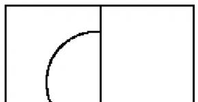
When working on a circular, the author noticed a great danger of the saw blade jumping off, especially when the blade hits metal parts. Therefore, in the design of the machine, special attention is paid to facing the window (groove for the circular disc) with plywood overlays (Fig. 4).

Rice. 4. The design of the saw (circular) table.
Installing a table with four upright legs includes telescopic leg joints. But it must be borne in mind that vibrations in the operation of the machine make the screw clamps not reliable enough. Therefore, it was necessary to supplement this device with locking pins.
The possibility of adjustment displacement of the ruler is provided by the guides welded to it, made of rods of 016 mm.
To facilitate milling, a pressure roller is provided, without which it is difficult to manually feed the workpiece to the milling cutter.
The drilling and milling device (Fig. 5) secures the workpieces to be processed and their movement relative to the tool. However, during the operation of the entire unit, the clamping force of the parts with a common clamp makes it difficult to move them along the cross slide. Apparently, it is better to mount the workpieces directly on the table. Naturally, when the details are not being processed on the table, the clamp must be removed from before. The same should be borne in mind in terms of equipping the table: the stop used when processing small parts is removed when processing a large part
A gas tank from a moped "Riga" was used in the machine. However, the stock of gasoline in it (8 liters) is not enough. It is better to use a larger tank by placing it next to the machine. I draw your attention to the alteration of the exhaust pipes from the gas engine to the muffler. To move the hot muffler away from the machine parts, it was necessary to make an extension from pieces of 01 "pipe using bent adapters.
When preparing pieces of metal profiles, I used a hacksaw for metal: this ensures a clean cut.
After manufacturing, the nodes should be painted. This should not be neglected: the paint not only protects against corrosion and gives the machine an elegant look, it also significantly reduces the noise from the machine.
Now about the order of work on the machine. First of all, they fill the belt drive for the selected type of drive: from an electric motor or from a gasoline engine. The electric motor is switched on according to the "delta" scheme for operation in a single-phase network. Therefore, it is run through capacitors. The load must be removed at startup. To do this, the tensioner is loosened (the belt tension is reduced) so that the drive pulley in the belt slips. After some unwinding, the belt tension is applied with a ratchet. The working shaft is gradually unwound. The start of the gasoline engine is also carried out with gradual loading.
For the selection of a quarter (for example, in the manufacture of a decorative strip-"silk" for finishing work), cutters are used with a small height of cutting teeth - up to 5 mm. The rotational speed of the cutter is about 3000 rpm. To perform this work, an additional ruler is first installed on the saw table. Stoppers are removed from the guide racks to protect the table from arbitrary lowering. Then, the tightening nuts are loosened for fixing the position of the metal tables relative to the saw table frame. Now these tables can be moved apart by the approximate radius of the cutter (while the cutter with the shaft is in the extreme upper position). Further, the clamping device of the lift rod is loosened until the rod can be turned (retractedly). This makes it possible to unscrew the tabs fixing the table posts (while the lifting pins of the lift must be brought under the posts). The working surfaces of both metal tables are brought out in one plane, and the table is gradually lowered until the cutter is set to the required height. In this form, the lift bar is fixed and the lambs are clamped. This completes the installation of the table. It remains to fix the sliding tables in the desired position (the optimal position is found by turning the shaft with the cutters).
For cutting a quarter, you can also install a circular of a small diameter and, without removing the stoppers and without touching the fastening of the metal tables, adjust the table height with a lift so that the saw blade provides the required cutting depth. In this position, the table is fixed with lambs. In this case, a small ruler is not needed and it is removed.
The need for a unit for drilling and milling face work arose as the need for mechanization of processing wood construction parts. At the end of the shaft, we had to make a socket for a Morse taper (for installing drills).
There are two ways to implement the fastening device of the workpiece. The first is generally accepted. This is the creation of a simple table on which the workpiece is fed onto the tool manually. In this case, only the installation (adjustment) of the table in height is needed. The second direction is a mechanical feed coordinate device. It was done by me in the described machine.
Wood is an inimitable, unique, environmentally friendly material, which makes it highly demanded and popular. Making products from this material is accepted in the world as the highest skill. Homemade woodworking machines are in demand among small entrepreneurs who fulfill individual orders.
Having at hand woodworking tools or a special machine, it is easy to show imagination and skill in all directions - to build a house, equip a summer cottage, make furniture and interior items.
In specialized stores, multifunctional machines are not cheap, so, as an alternative, you should consider making your own.
Features of the units
What kind of woodworking machines are there? What types of work are easy to perform on them?
Basically, on machines, they do trimming and cutting of wood, its grinding, and additionally - turning work. Based on this, the machines are divided into the following types:
- universal;
- specialized;
- narrow profile.
With the right approach and manufacture, homemade units are versatile and able to cope with all these tasks.
The basics of the initial stage, which must be taken into account in order to make a woodworking machine with your own hands.
Please note that the required amount of space is required to install the machine. It is advisable to have a separate room for this, so that all materials and devices are at hand.
Before proceeding with the preparation of parts for assembly, it is necessary to draw up accurate drawings. If you do not have experience in this area, you should resort to the help of a wizard or find information on the Internet.
Components of the device
Parts that most often consist of woodworking machines.
Bed (body, work table)
The future structure will be attached to it. They are often made of steel, cast iron, that is, the structure must be quite heavy and stable so that the machine is held securely on it. All parts are held together by welding, which is more durable.
Sometimes assembly is carried out using bolts, but such fasteners have the ability to loosen, therefore, in such cases, you will have to regularly check and tighten the structure. Often, the bed is additionally reinforced with cement - in this case, the workplace will be stationary. But there are designs with a movable table.
Shaft mechanism
Has three types:
- saw;
- knife;
- spindle.
A cutting mechanism is installed on the shaft from the end, and on the other side is a belt drive from the control unit. The shaft is located at the top of the work bed and is often 30 cm thick in circumference.
Cutting unit
The part that will be directly responsible for wood processing. Changes depending on what operation needs to be done. This is sometimes a circular knife, cutter, grinding or emery wheel, jigsaw knife.
Control block
The mechanism of the machine, that is, the engine. He is responsible for the work, adjusting the frequency of rotation of the working parts. Special requirements are imposed on it: the power must be 1.5–3 kW, and the speed must be 1.5–2.5 thousand revolutions. The engine is mounted at the bottom under the work table.
Guide part
This is a moving bar, with the help of which the width and thickness of the cut parts are adjusted, the manipulation helps to avoid wasting time on additional marking, creates a certain safety when holding wooden blanks. Installed on the top of the bed with the ability to move and securely fasten.
Optional equipment
A homemade woodworking machine requires the introduction of several parts with which the mechanism can repeat the maneuvers of an industrial unit. There are additional parts included in the body.
Wiring - the power of electricity must pull 380 V. The wiring must be done correctly, in compliance with all safety standards. The wires are secured so that there is no chance of getting into the engine or cutting mechanisms.
Protective covers - are installed on all dangerous parts of the machine and are designed to protect parts of the body from damage in case of accidental slipping of parts during processing. Most often they are made of sheet metal or PCB.
Assembling the device
The main problem that often arises during manufacturing is component parts. A multifunctional machine requires attention and scrupulousness from the master. Experts in this field advise purchasing factory mechanisms and parts. They are made of tool steel and are quite durable and reliable in operation.

If there is no possibility of ordering factory products, you should use available tools, for example, a mechanism from a chainsaw or a circular one. In this case, it is worth considering that the parts will not be so durable, and homemade units will not have a high degree of safety.
After all the details and necessary materials are prepared and the assembly diagram of the machine is clear, you need to proceed directly to the process itself. According to the drawings, the bed is first assembled and reinforced. Then the motor and rotor are attached.
Any wood machine will be able to help the owner in everyday life. Pre-assembled and turned correctly parts will make the assembly very fast. After installing all the necessary structures, it is necessary to check the starting mechanism and the operation of the engine. And only after that it is necessary to install the necessary cutting part and try the machine in operation.
If all the points were observed with accuracy and all the constituent parts are made and fixed correctly, then homemade woodworking machines will not be inferior in their functionality to the factory ones. All that remains is to observe safety precautions and work on the machine for your own pleasure.