Stabilizing the speed of a drilling machine for drilling circuit boards. General information about drilling machines
A drilling machine for printed circuit boards belongs to the category of mini-equipment for special purposes. If desired, you can make such a machine yourself using available components. Any specialist will confirm that it is difficult to do without the use of such a device in the production of electrical products, the circuit elements of which are mounted on special printed circuit boards.
General information about drilling machines
Any drilling machine is necessary in order to ensure the ability to efficiently and accurately process parts made from various materials. Where high precision processing is required (and this also applies to the process of drilling holes), manual labor must be eliminated as much as possible from the technological process. Anyone can solve similar problems, including homemade ones. It is practically impossible to do without machine equipment when processing hard materials, for drilling holes in which the efforts of the operator himself may not be enough.
Design of a benchtop belt driven drill press (click to enlarge)
Any drilling machine is a structure assembled from many components that are securely and accurately fixed relative to each other on a supporting element. Some of these nodes are rigidly fixed to the supporting structure, and some can move and be fixed in one or more spatial positions.

The basic functions of any drilling machine, through which the processing process is ensured, is the rotation and movement in the vertical direction of the cutting tool - the drill. On many modern models of such machines, the working head with the cutting tool can also move in a horizontal plane, which allows this equipment to be used for drilling several holes without moving the part. In addition, automation systems are being actively introduced into modern drilling machines, which significantly increases their productivity and improves processing accuracy.
Below, as an example, several design options for boards are presented. Any of these diagrams can serve as a model for your machine.
Drawings of machine parts (click to enlarge)

Let's figure out what all these components are for and how to assemble a homemade mini-machine from them.
Structural elements of a mini drilling machine
Do-it-yourself mini-drilling machines can differ significantly from each other: it all depends on what components and materials were used for their manufacture. However, both factory-made and home-made models of such equipment work on the same principle and are designed to perform similar functions.

The load-bearing element of the structure is the base frame, which also ensures the stability of the equipment during the drilling process. Based on the purpose of this structural element, it is advisable to make the frame from a metal frame, the weight of which should significantly exceed the total mass of all other equipment components. If you neglect this requirement, you will not be able to ensure the stability of your homemade machine, which means you will not achieve the required drilling accuracy.
The role of the element on which the drilling head is mounted is performed by a transitional stabilizing frame. It is best made from a metal strip or corners.

The bar and shock-absorbing device are designed to ensure vertical movement of the drilling head and its spring-loading. Any structure can be used as such a bar (it is better to fix it with a shock absorber) (the only important thing is that it performs the functions assigned to it). In this case, a powerful hydraulic shock absorber can come in handy. If you don’t have such a shock absorber, you can make the bar yourself or use spring structures removed from old office furniture.
The vertical movement of the drilling head is controlled using a special handle, one end of which is connected to the body of the mini-drilling machine, its shock absorber or stabilizing frame.

The engine mount is mounted on a stabilizing frame. The design of such a device, which can be a wooden block, a clamp, etc., will depend on the configuration and design features of the remaining components of the drilling machine for printed circuit boards. The use of such a mount is determined not only by the need for its reliable fixation, but also by the fact that you must bring the electric motor shaft to the required distance from the movement bar.
Choosing an electric motor that can be equipped with a mini-drilling machine that you assemble yourself should not cause any problems. As such a drive unit, you can use electric motors from a compact drill, cassette recorder, computer disk drive, printer and other devices that you no longer use.

Depending on what kind of electric motor you found, clamping mechanisms for fixing drills are selected. The most convenient and versatile of these mechanisms are the chucks from a compact drill. If a suitable cartridge cannot be found, you can also use a collet mechanism. Select the parameters of the clamping device so that it can hold very small drills (or even micro-sized drills). To connect the clamping device to the motor shaft, it is necessary to use adapters, the dimensions and design of which will be determined by the type of electric motor selected.

Depending on which electric motor you installed on your mini-drilling machine, you need to select a power supply. When making this choice, you should pay attention to the fact that the characteristics of the power supply fully correspond to the voltage and current parameters for which the electric motor is designed.
Diagram of automatic speed control depending on the load for a 12 V engine (click to enlarge)
The procedure for assembling a homemade device
As practice shows, it is most convenient to assemble a homemade machine for drilling holes in printed circuit boards in a certain sequence. You must act in accordance with the following algorithm.
- The frame is installed, and legs are attached to its underside, if they are provided for in the design.
- A movement bar and a holder frame on which the drilling head will be mounted are attached to the assembled frame.
- The holder frame is connected to a shock absorber, which is also fixed to the equipment frame.
- A handle for controlling the movement of the drilling head is installed, connected to a shock absorber or holder frame.
- An electric motor is mounted, the position of which is carefully adjusted.
- A collet or a universal drill chuck is attached to the shaft of the drive motor using adapters.
- A power supply connected to the electric motor via electrical wires is being installed.
- A drill is installed in the chuck and securely fixed in it.
- The assembled homemade machine is tested by trying to drill a hole in a dielectric sheet with its help.
To ensure that your homemade mini-drilling machine can always be disassembled and modified, it is best to use bolts and nuts to connect its structural elements.
Answer
Lorem Ipsum is simply dummy text of the printing and typesetting industry. Lorem Ipsum has been the industry"s standard dummy text ever since the 1500s, when an unknown printer took a galley of type and scrambled it to make a type specimen book. It has survived not only five http://jquery2dotnet.com/ centuries , but also the leap into electronic typesetting, remaining essentially unchanged. It was popularized in the 1960s with the release of Letraset sheets containing Lorem Ipsum passages, and more recently with desktop publishing software like Aldus PageMaker including versions of Lorem Ipsum.
The automatic speed controller works as follows - at idle speed the drill rotates at a speed of 15-20 rpm, as soon as the drill touches the workpiece for drilling, the engine speed increases to maximum. When the hole is drilled and the load on the engine is relieved, the speed drops again to 15-20 rpm.
Diagram of automatic engine speed control and LED backlight:
The KT805 transistor can be replaced with KT815, KT817, KT819.
KT837 can be replaced with KT814, KT816, KT818.
By selecting resistor R3, the minimum engine speed at idle is set.
By selecting capacitor C1, the delay in turning on the maximum engine speed when a load appears in the engine is adjusted.
Transistor T1 must be placed on a radiator; it gets quite hot.
Resistor R4 is selected depending on the voltage used to power the machine according to the maximum illumination of the LEDs.
I assembled a circuit with the indicated ratings and I was quite satisfied with the operation of the automation; I replaced the only capacitor C1 with two 470 µF capacitors connected in parallel (they were smaller in size).
By the way, the circuit is not critical to the type of engine, I tested it on 4 different types, it works fine on all of them.
LEDs are attached to the motor to illuminate the drilling site.
The printed circuit board of my regulator design looks like this.
With the invention of machine tools, humanity has made significant progress in the production of various types of parts and mechanisms. Machine tools have become a real help for anyone who intends to process metals, wood and any other materials.
After all, these devices are initially intended to perform quite specific work that you will not be able to perform efficiently in any other way.
Homemade machine for printed circuit boards from a guide rail
Such equipment also includes a drilling machine for printed circuit boards, which is used in electromechanics and related manufacturing fields.
1 General information
Any machine is a special device that is assembled from several components. The purpose of this device is to give a person the ability to process a particular tool with great precision. That is, practically eliminate manual labor from the process.
This is absolutely necessary in work where precision is needed. If you use a part made of metal or any precision material, then you simply cannot do without using a machine.
Read also: about the purpose and types of collets.
The machine consists of a frame, adapters, installation for the engine and several other mechanisms. All of them are assembled into a single structure, which is rigidly fixed in one or more positions.
Standard and cheapest machines or mini machines, if we are talking about equipment that intended for processing miniature parts, can only move along one axis. That is, the movement of the working drill is performed from top to bottom. This is the basic function of the machine, without which it cannot be called a machine.

Pneumatic mining drill for machine
More advanced models can be precisely adjusted to a specific coordinate, which is set on the table. These could even be semi-automatic or automatic models.
As you yourself understand, it is the clear fixation on a durable frame and the ability to practically eliminate the human factor directly in the execution of drilling work that is the main advantage of the machines.
1.1 Features of PCB cutting machines
Printed circuit board machines are one of the types of such equipment. But such units, as a rule, are mini-samples. And this is quite obvious, because they need to work with printed circuit boards.
For those who are not familiar with electrical engineering, let us clarify that printed circuit boards are essentially the bases for any microcircuit or electronic mini-chain. Almost every device has at least one printed circuit board in its design. This is especially true for devices that run on electricity.
To create uniform standards in electrical engineering and create a stable foundation, printed circuit boards were introduced. They are made from dielectric material onto which various parts and connections are screwed or soldered.
The board can contain either a small transistor and a lead to it from a battery, or a huge number of parts so miniature that an unprepared person will not even consider them(we are talking about computer equipment).
Of course, in this situation it is worth noting the huge number of printed circuit boards that differ in their design, material used, etc. But we note that they are all a variety of one element, which serves as the basis for microcircuits.
The simplest boards are equipped with additional elements by screwing them in and then soldering them. As you understand, to screw the parts you need to make holes in the board.
Read also: about TV machines and their purpose.
Moreover, they must be done with filigree precision. A discrepancy of even half a millimeter can be, if not fatal, then very noticeable. Especially if you are going to fill the board completely.
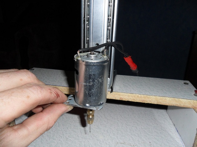
Installing the drill on the machine
Just look at the fact that drills for a mini-machine for printed circuit boards can start from samples of 0.2-0.4 mm in diameter. And this is if we talk about cheap machines. More advanced equipment for creating complex chips will use even smaller tools.
As you yourself understand, processing such parts manually is not an easy task. Even if you manage to make a couple of holes in the right place and the right thickness, the process will take too much time, and the result can be ruined by a single mistake.
Using a machine for printed circuit boards, the work is greatly simplified and becomes almost mechanical. As well as its productivity increases. And the design of such equipment is not complicated, so you can create it yourself.
to menu
2 Machine design
The design of a mini-machine for processing printed circuit boards has a fairly simple circuit. In fact, this machine is not much different from standard drilling models, only it is much smaller and has several nuances. We almost always consider a mini-table drilling unit, since it will have dimensions that rarely exceed 30 cm.
If we consider a homemade sample, it may be a little larger, but only due to the fact that the person who assembled it with his own hands simply could not optimize the design properly. This happens if there are simply no suitable parts at hand.
In any case, the machine, even if it is assembled with your own hands, will have small dimensions and weigh up to 5 kilograms.
Let us now describe the design of the machine itself, as well as the parts from which it must be made. The main components for assembling mini-devices for drilling boards are:
- bed;
- transition stabilizing frame;
- moving bar;
- shock absorber;
- handle for manipulating height;
- engine mount;
- engine;
- power unit;
- collets and adapters.

This is what a finished homemade drilling machine for printed circuit boards looks like
So, the list of equipment used is quite lengthy, but in fact there is nothing complicated here.
2.1 Analysis of specific parts
Let us now turn to the specific details that have already been mentioned above, and also give recommendations for their selection.
To begin with, we note that we are now describing a homemade machine, which, in fact, can be assembled from improvised means. The design of factory samples differs from the one described by us only in the use of specialized materials and parts that are almost impossible to create at home. I'll have to buy it.
A homemade mini-machine, like any other machine, begins with a bed. The bed serves as a base, the entire structure is supported on it, and the supporting part on which the board being processed is mounted is mounted on it.
It is advisable to make the bed from a heavy metal frame. Its weight should be greater than the weight of the rest of the structure. Moreover, the discrepancy can be quite impressive. The only way you will achieve stability of the unit during operation. This is especially true for models that are assembled with your own hands.
And don’t be fooled when you see a mini console. A mini-machine is the same machine, and it still requires high-quality stabilization. Legs or something similar are often screwed under the bed to further secure its position.

Homemade drilling machine with stabilizing frame
The stabilizing frame is the mount for the entire mechanism. It is made from slats, corners or something similar. Preferably use part. The movement bar can be of a wide variety of designs and is often combined with a shock absorber. Sometimes, the shock absorber itself is a bar for movement.
These two parts perform the functions of vertical displacement of the machine during operation. Thanks to them, the machine can be operated quickly and without unnecessary effort.
There are a lot of solutions for making such parts. Starting from homemade sliding slats on a spring or removed from office furniture, to professional oil-type shock absorbers.
The manipulation handle is attached directly to the machine body, shock absorber or stabilizing rail. With its help, you can apply pressure to the structure, lowering and raising it at will.
A bar for the engine is already attached to the stabilizing frame. It could even be an ordinary wooden block. Its task is to output the engine at the required distance and securely fixing it.
The engine is mounted on a mount. You can also use a huge number of parts as an engine. Starting from drills, and ending with engines that are removed from printers, disk drives and other office equipment.

Drill bits for drilling holes in printed circuit boards
Collets and adapters are attached to the engine, which will be the base for attaching the drill. Here we can only give general recommendations, since adapters are always selected individually. Their choice will be influenced by the motor shaft, its power, the type of drill used, etc.
The power supply for the mini-machine is selected so that it can supply the engine with the required voltage in sufficient quantities.
2.2 Machine assembly technology
Now let's turn to the general algorithm by which the unit for drilling printed circuit boards is assembled with your own hands.
- We mount the frame and attach the legs to it.
- We install the holder frame of the main structure on the frame.
- We attach the movement mechanism and shock absorber to the frame.
- We mount the mount for the engine; as a rule, it is fixed to the movement frame.
- We install the handle on the engine mount.
- We install the engine and adjust its position.
- We screw the collet and adapters to it.
- We mount the power supply, connect it to the engine and the network.
- We select and fix the drill.
- We test the operation of the mechanism.
All connections and their type you can choose at your discretion. However, it is recommended to use bolts and nuts in order to be able to disassemble the structure at the right time, replace its components, or improve the entire operation of the machine.
to menu
2.3 Homemade machine for drilling printed circuit boards (video)
Do-it-yourself drilling machine for printed circuit boards.

Almost a year ago, I finally assembled a machine for drilling printed circuit boards. Until then, I, like many others, used a small engine with a cartridge mounted on the shaft.
One day I got tired of all this, and I decided to design something of my own. At first I thought about constructing something of my own design, fortunately I had already selected something for the feed mechanism and scoured the Internet in search of suitable designs to repeat.
I must say that there are still designs that deserve attention, and are made beautifully and competently. But there are some that look like they were made with an axe.
But then one day at a flea market I came across a skeleton from a microscope in a very poor condition. I can’t imagine how people from science were able to bring him to such a state.
Bargained for ten euros. Already at work, I went through all this stuff, washed it, restored the mechanics and removed all the play. Next, I removed the inclined console and instead made a horizontal one from D16T. The electric motor mount was made from the same material. Now the design was more compact in height, and externally acquired the outline of a machine. The parts were fastened to the frame using pins and bolts.
I’ll go off topic a little and tell you about myself. I work in a car repair shop, so in my design I used everything that was lying under my feet and could be used. As for the equipment, I mainly used a table-top drilling machine made by a semi-artillery manufacturer. I did all operations such as drilling and milling, grinding and some turning on it. The tools I used were files, needle files, drills, reamers, taps, a hacksaw and much more, too many to list. In general, it took me a couple of months to do all this (everything was done in my free time from work). Everything turned out great, but disappointment set in after the first turn on. The reason was the vibration created by the cartridge.
It so happened that a long time ago I came across a jammed Opel fuel pump. And after thinking a little, I converted it into a drill. The characteristics of this engine are quite solid. Once I tried to drill steel with it using a ∅6mm drill.
I should note that not every electric fuel pump can be suitable for these purposes. I have a lot of this stuff lying around, and I once “anatomized” a dozen different models. There are quite a lot of different unpleasant moments associated with the design of the electric motor itself. Although, with great desire and skill, I think you can do anything.

When you hold the engine in your hand and drill, small flaws such as vibration and eccentricity are almost not noticeable. In the machine everything is different. And then I began to look for another cartridge for my engine. This cartridge had a threaded fit on the shaft, and making a new adapter for it would be a waste of time. I didn’t even want to consider the collet option. In my opinion, the chuck is a universal tool, and the collet provides drills of certain sizes. The diameter is slightly wrong and the drill either does not insert or goes in circles.
And I found what I was looking for at one tool seller. The cartridge turned out to be made in the Middle Kingdom, but it looks surprisingly quite cultured, the workmanship is simply excellent. And in terms of money, it’s not that expensive, only 8 European rubles, translated into our Moldovan lei.

Here is the cartridge data
Dimensions:
- outer diameter - 21.5mm
- larger cone diameter - 6.350 mm
- smaller cone diameter - 5.802 mm
- cone length 14.5 mm
- ellipse 0.02 mm
Cone: JT0 (2 degrees 49 minutes 24.7 seconds)
Drill diameter: 0.3mm - 4mm
Weight: 73.3g
And even the cartridge seller promised to help with an adapter for the cartridge. But time passed, and there was still no adapter. About six months later, without waiting for the coveted adapter, I decided to turn to my familiar turners. But even there I was disappointed. In principle, I didn’t have much hope in this regard, because I knew that you couldn’t get great accuracy on machines made in the 70s and 80s. Then I decided to try to make a cone on my own. It would seem that the task is impossible, but as they say, everything ingenious is simple. I noticed one car detail. It is a nozzle from mechanical fuel injection of gasoline cars of the 80s and 90s produced by BOSCH.


In the first photo: nozzles (injectors) made of 1 – steel, 2 – brass, 3 – cut and drilled blank, 4 – finished blank, 5 – blank mounted on the axle.
What attracted me to this detail? And first of all, because it has a ready-made through hole. Secondly, it is made with very high precision. This is the so-called precision mechanics. Thirdly, I already have quite a bit of this stuff that has fallen into disrepair. Therefore, there was something to experiment with. In the end, after some experiments, we managed to get what we wanted.
As I already said, I only have a tabletop drilling machine at my disposal. This is where I made my preparations. I drilled the holes in a somewhat unusual way, that is, I clamped the workpiece itself in the machine chuck, and the drill in a special device made of two metal bars with holes of different diameters drilled in the center (see figure).

You can also use a tap holder. When drilling, it is advisable to use new drills and the overhang of the drill should be as short as possible. Then the probability of deviation from the center will be minimal. Any object with parallel planes and through holes can be placed under the protruding lower part of the drill. Any bushings, bearings, chipboard or MDF boards will do.
Initially, a hole is drilled to match the diameter of the motor shaft. In this case, the diameter of the motor shaft of my machine is 6 mm. The diameter of the drill is taken 0.1 mm less, that is, 5.9 mm. Next, a through hole is drilled for the M 4 thread. The thread is needed so that the workpiece can be pressed out from the shaft if necessary. It is advisable to make several pieces of blanks, since it is possible that the workpiece may run out on the shaft, or the hole may deviate from the center.
When making a workpiece from a calibrated rod, first, after preliminary marking, you must first make an entry with a centering drill. If it is possible to make a workpiece on a lathe, then the task is much simpler. But this is only the first stage. Next, you need to slightly heat the workpiece and place it effortlessly on the motor shaft. After cooling, the workpiece is held on the shaft very firmly without any additional screws. This is the so-called hot landing. After this, I checked the workpiece for runout and center deviation. I was satisfied with the second one made. The surfaces of the mating parts should not have traces of lubricant, since when heated, the lubricant burns out and the mating parts seem to stick together. In the future, if necessary, it will be very difficult to separate them.
Somehow, after talking with a friend from my student days, the idea of further continuation of the idea appeared. After sitting at the computer for a couple of hours, I modeled a device for grinding a cone. Making this equipment took another couple of hours. And manufacturing, that is, grinding the cone, takes about forty minutes. And then with breaks for measurements. You will laugh, but I did all this in my kitchen, securing this entire structure with two clamps on a stool.
In general, the result exceeded all my expectations; when the machine was running, the drill seemed to stand still. If previously, each time you drilled holes, you had to stop the engine to get to the future center of the hole, but now you can drill without stopping and without the risk of breaking the carbide drill.
Whether anyone has done something similar before me or not, I don’t know. At least I haven't found anything like it anywhere. The fact is that it is still possible to achieve fairly high accuracy in artisanal conditions without resorting to the help of a machine operator. True, if the arms and head grow from the shoulders.
The model of this device looks like this.


Front and back appearance of the device.

Processed cone (enlarged).

For grinding, it is advisable to use a new stone, and the rotation of the part and the stone should be mutually opposite.
By rotating screws A, A1 and B, B1 we feed the part. By loosening screw B1 and screwing in screw A1, we give the part a taper. The guides (item 1) were made from scraps of a square pipe with a cross-section of 15×15, the thrust plates (items 2 and 3) were steel, 5mm thick. Bolts (pos. 6) secure the thrust plate to the fixed plate (pos. 5). The plate (pos. 2) is attached to the movable plate (pos. 4). Guide grooves in the movable plate (item 7). It is very convenient to use hex head bolts as fasteners, especially feed bolts pos. A, A1 and B, B1. By rotating them with a hexagon, the feed is very easily controlled. It is advisable to leave a gap of about 1mm per side between the guides and the movable plate. The plate itself should move in the longitudinal direction quite tightly, with a slight creak. Bolts (pos. 7) achieve the necessary adjustment. The material used to make the sanding fixture can be chipboard, MDF, thick plywood, or sanded hardwood. I used 22mm thick MDF.
Different materials have their own specific disadvantages that need to be taken into account. Thus, MDF boards tend to delaminate in the longitudinal direction when screwing in the bolts. Wood is prone to splitting.
Now a few words about the design of the machine.
The engine was mounted in the frame according to the classical scheme. Similar from the site ydoma.info/samodelki-mini-sverlilnyj-stanok.html?cat=5.
This option provides a very reliable and rigid connection between the engine and the structure.

I combined the backlight with a magnifying glass, it turned out very convenient in my opinion. The light is always directed from the eyes towards the instrument.


Again, I made a flexible sleeve from what I had, took aluminum balls ∅ 9 mm from deployed seat belts and connected them in pairs with a copper tube. I connected them together with short pieces of plastic gas pipeline tube with an internal diameter of 8 mm. Having preheated the ball mounted on a steel rod, the tube is placed on the ball until a hemisphere is formed on the tube. It's that simple. What this joint looks like is shown in the figure.


The lifting and lowering wheel was machined from ebonite ∅ 50 mm and tightly fitted onto the standard one. Management has become much more convenient than before.
I didn’t think it was necessary to add an additional lever.
The feeding of the tool during drilling is already very easy and smooth.

I didn’t bother too much with the power supply (I think the simpler the more reliable), I made it based on a 100-watt torus with a simple rectifier. Although there was an idea to make an impulse generator, fortunately there is a good proven circuit. 10-position speed selector switch. Supply voltage is from 4 to 14 V. The case was taken from a 3.5″ floppy disk drive (no one probably uses this stuff anymore). True, I changed it slightly.
Controlling the motor activation via a pedal does not require hands when drilling boards.
Well, after finishing the car, the painter painted all the parts separately.
Running around, I spent about 40 euros on all this, and in general I think that it’s not very expensive for such pleasure.
Somehow like this.
Once upon a time, in the early 80s, I had a drill for PCBs based on the GDR - an electric motor and a small drill chuck on the 1st Morse cone.
The type of motor was not preserved, but the diagram was copied in a notebook.
In those years there were no home computers, and all interesting schemes and brain research were recorded in general notebooks in a box, 96 sheets each, costing 44 kopecks.


The circuit worked according to the algorithm: small load - the cartridge rotates slowly, increasing load - the cartridge rotates faster. It was very convenient to use for drilling holes in PCBs; I got into the core and the speed increased.
Many years have passed, the drill has long since sunk into eternity. Recently I was puzzled by the problem of drilling holes in PCBs. Due to the lack of such transistors (especially P-701), it was necessary to convert the circuit to modern parts:


The board is universal: if there is a KT972, we install it and a jumper from the base to the emitter of a small transistor; if there is no KT972, we install the KT315 and an analogue of the KT805, as in the photo.
Another scheme developed in the head of another author: Edward Nedeliaev (http://www.cqham.ru/smartdrill.htm). I came across this link after a week of unsuccessful attempts to get the circuit to work with a DPM type motor. Although, as we know from the classics, what one homosapien has assembled, another homosapien can always take apart. As it turned out, the circuit does not work with DPM motors, you see, only give it engines of the DPR series.

But there is no DPR motor and there is no desire to buy one, but there is such a box and a picker from it.

From this point begins the laboratory work on the topic “Choose the control of the PICKER for P/BOARDS.” The Internet is full of different schemes, simple and not so simple, for controlling drill motors for PCBs. Let's look at some of the most common ones:
1. transistor-based regulator without the use of microcircuits (the K142EN series is ignored)
2. regulator on transistors and microcircuits.
3. regulator on transistors and a microcontroller.
4. voltage regulator (let's skip it, it is of little interest for use in the purposes and tasks under consideration)
First we will try the scheme of A. Moskvin, Yekaterinburg:


The scheme perfectly fulfills its functions and responsibilities:
1. touch controlled (start/adjust/stop)
2. changes speed
3. engine slows down
4. Requires virtually no setup
If you use a pad the size of 1 kopeck coin divided in half as a sensor, then by applying your finger it is very convenient to turn on and regulate the engine speed.
In the magazine “Radio” for 2009 there was a different scheme for DPM motors. It was invented by S. Saglaev, Moscow. I had to change some ratings to suit my motor.


The scheme works quite well, but is somehow thoughtful. This may have something to do with the engine I have.
The second experiment we will take are the so-called PWM regulators.
There are a great many variants of schemes and the authors are simply legion. For this reason, the names and surnames of the heroes are not given here.


The circuits work, but are more suitable for controlling the speed of a fan with a commutator motor. More acceptable parameters for a drill are circuits based on the NE-555 timer:


One of the circuit solutions is the use of feedback. Two such schemes were borrowed from the Arsenal forum (http://www.foar.ru):


These variants of schemes are worthy of attention and repetition. It should be noted that the version with the KD213 diode had the honor of being installed in the case, and took up empty space in the gray box along with a picker and drills. Probably simple so-called PWM regulators are most likely suitable for a stationary drill like this:

Next in line is a microprocessor type of drill. The West, as usual, helped us with the circuit design: http://mondo-technology.com/dremel.html I made this circuit three years ago, the killed Dremel acted as a guinea pig. An imported 24 volt motor was installed inside and powered by this circuit:


The design turned out to work remarkably well, is still used at work and deserves only praise. By the way, the holes in the PCBs in the photographs were made by her.
As an option for a drill, I tested the ATtiny13 circuit (by hardlock, http://www.hardlock.org.ua/mc/tiny/dc_motor_pwm/index.html):


It’s a nice design that works well, but I would like to emphasize again that it is more suitable for a stationary drill.
And finally, a design that captivated us with its repeatability and ease of use. The scheme was invented and implemented back in 1989 by Bulgarian Alexander Savov:


The scheme works perfectly according to the algorithm outlined at the beginning:
1. small load - the chuck does not rotate quickly.
2. the load increases - the chuck rotates faster.
The circuit is completely indifferent to which motors it works with:


All engines that were available at home were tested under the control of this design and performed the test perfectly. The results exceeded all expectations. A slight adjustment with resistor RP1 to the minimum rotor speed you need and resistor RP2 - stable, jerk-free rotation, and that’s it, the engine works.
P.S. Do not forget about the power supply, which should not keep your picker on a current starvation.
All questions, as always, in the Forum.
Ghostgkd777 › Blog › Drilling machine for printed circuit boards
Hi all!
I've been working towards this for a long time, finally I got around to it and in 12 hours I made a little stamp picker.
I took the kinematics with a moving engine. It was a pun)) In general, the engine with the cartridge is lowered.
This unit is based on the slide and carriage of a CD-ROM or any other drive. I mounted the engine on it, spring-loaded it to the frame, attached a lever for lowering, secured this entire structure to an aluminum corner, which in turn was attached through a spacer to the base of a fiberglass slab.
Photos of the entire structure are below.
carriage with angle for engine
the spring is in place, the end of the upper position of the carriage is installed
The motor is from a hair dryer, quite high-torque
a separate conversation about the collet chuck
It's still crap, I'll tell you... not all drills hold well. Working with him brings a lot of negative emotions. And changing it to a normal jaw chuck is too big for this motor. Therefore, this version of the drill is recognized as a temporary solution until the purchase of a 24V motor and a normal chuck. There we will build a more impressive picker))
But it would be too easy to stop there! I attached a circuit to the engine with automatic control of engine speed depending on the load, which I saw from the cats and posted Sansey. By the way, there is a very good overview of engine control circuits there. I recommend!
Dear admins and moderators, please do not consider this as an advertisement for another resource. The material is interesting, people will find it useful, but copying it into your blog is somehow not good.
I went through and adjusted it to fit the parts I had.
The tip was installed to shunt the BE VT2 because in the upper position of the carriage it is closed. It has only one contact (from the same hair dryer as the motor), I was too lazy to look for normal ends))
- City: Rubtsovsk
Homemade drilling machine for printed circuit boards
Well, if it’s about an exhibition of drills, then I’ll also take part
So here it is:
A little description: the engine runs from a 220V/6V transformer through a rectifier, although according to its performance characteristics it should be powered by 12 volts (we are looking for such a power source); You can use any drill bits up to 3mm. Now a homemade adapter from 4mm (shaft) to 3mm (maximum drill diameter) is mounted on the motor shaft, but this is temporary because changing drills takes an extremely long time (find a suitable bushing, center it.). Ideally, it needs a collet chuck for a 4mm shaft. Right now I'm using a 1mm drill bit.
The next two photos show my joints. Unfortunately, I could not achieve parallelism between the axis of the rack and the axis of the shaft. But surprisingly, this does not interfere with drilling in any way (checked several times):
But this detail is special, because I poured it myself from duralumin
I did not make any levers for raising and lowering the drill. I control the machines like this:
I like it, it's convenient.
And here is the textolite that was tested on the first day of operation of the machine:
- Moscow city
- Name: Maxim Bratersky
Homemade drilling machine for printed circuit boards
about ten years ago I bought a coordinate table in Mitino with 100 by 100 mm DSHI200-1 engines.
“CNC9 assembled from a 386sx computer. The program output on LPT 8 bits, 4 per engine.
each bit controlled one transistor. the file for drilling was prepared by PCAD7 ORCAD9.
- Tomsk city
- Name: Dmitry
Homemade drilling machine for printed circuit boards
Very interesting designs, I also recently made myself a machine from wood and a piece of a guide from a printer with a carriage. It seems possible to live, but... The feed is organized anyhow, i.e. the engine is spring-loaded and lowers only when you press it. Again, there is no rigidity, although I attached it with corners. Photo in the evening. I’m thinking of making the machine more decent, everything would be fine, but I can’t find the rack and pinion feed mechanism, there are no microscopes or unnecessary parts from old equipment. I read somewhere here that a door closer would work very well, but it costs a kilo ruble or more, so it’s not an option. But my machine needs a good reach, because... the boards are also 30x30 cm, it comes out to 150 mm from the drill to the base of the stand. The base and the stand are not a question, but the feed mechanism, and I don’t know if it doesn’t jam.
- Tomsk city
- Name: Dmitry
Homemade drilling machine for printed circuit boards
Here is the photo.
A very modest craft, compared to others.
There is only one consolation - as soon as I finish a large series of boards, I’ll start building something more decent. A hand drill is no match even for my monster!
— in this review we will talk about making a miniature drilling machine at home from improvised materials. The article is intended mainly for radio amateurs who often have to make their own printed circuit boards. But such compact equipment as the machine presented below will be useful not only in the field of electronics, but also in other business matters.
The design was based on parts from a failed CD ROM from a computer. Or rather, you will only need a metal frame with a pair of guides and a carriage installed on its plane; this fragment is shown in the photo below. My goal, of course, was to assemble a drill from scrap materials. That is, from what was on the farm and could be useful in building such equipment.
The engine will later be mounted on the sliding carriage, and then it will be assembled itself DIY drilling machine. To secure it, a special holder in the form of a bracket was previously made from a piece of 2mm sheet steel.
Electric motor
I drilled holes in the holder to match the size of the electric motor shaft and, accordingly, for the screws that will hold the bracket with the motor. Initially, an electric motor DP25-1.6-3-27 was used for the drilling device, operating from a constant voltage of 27v and developing a power of 1.6 W. See photo:
During testing of this motor, it was found that it did not have enough power for drilling in fiberglass. 1.6W is clearly not enough for this, you increase the load a little and the engine becomes weaker.
This photo shows DIY drilling machine with an electric motor DP25-1.6-3-27, a version of which was initially intended to be used:
Due to the fact that the power unit is not very productive, we had to abandon it and look for a motor of appropriate power. Of course, it took some time to find the right engine, so the manufacturing process was paused a little. But as they say, “the world is not without good people,” and a friend gave me an electric motor from an old non-working printer.
New electric motor
The newly purchased engine did not have a nameplate with markings, therefore, I do not know its power for certain. But its power was quite enough to collect DIY drilling machine. A metal gear is pressed onto the armature shaft. The diameter of the shaft on the engine is 2.3 mm. Next, I removed the gear from the shaft, and replaced it with a collet clamp and tried to drill several holes with a 1.2 mm drill. The result, of course, pleasantly surprised me; this motor did an excellent job of drilling 3 mm PCB with a supply voltage of 12v.
Here is how I attached the motor using a holder to the sliding carriage:
The support for the drilling device is made of a ten-millimeter piece of fiberglass.
These are the prepared parts for the base of the device:
To ensure stability, the drilling machine is assembled with your own hands; rubber support legs are mounted in the lower part of the base:
Device design
The metal structure of the device has the image of a console, in other words, a supporting chassis with an electric motor installed on it using two special holders. The frame with the motor is installed at a short distance from the bottom of the machine. This version of the system made it possible to drill large-sized PCB. A sketch of the device is shown below:
Below is a picture of a finished drilling machine
In the working part of the device in the photo you can see the LED installed for illumination:
The image shown shows that the backlight is too bright. In reality, everything is illuminated very correctly:
The design, made in the form of a console, makes it possible to make holes in workpieces that are large in width, more than 140 mm, and, of course, long.
Measuring the usable drilling area:
As the image shows, the length of the plane from the front of the movable carriage of the machine to the center of the drill is 69 mm. That is, the width of textolite blanks for printed circuit boards can be approximately 135 mm.
Movable mechanism
To lower and raise the drilling mechanism, a special push-action lever is provided:
To fix the drilling unit over the workpiece before starting drilling, and then return it back, that is, reverse is provided by a return spring. It is placed on the guide axis:
This image shows a diagram for setting the speed of the electric motor in automatic mode, which depends on the degree of load.
Drilling printed circuit boards is a real headache for an electronics engineer, but our new device will help alleviate some of it. This simple and compact addition to your mini drill will extend the life of the motor and drill bits. Schematic, board, setup instructions, video - everything is in the article!
Why do you need a speed controller?
Typically, mini drills are built on the basis of conventional DC motors. And the speed of such engines depends on the load and applied voltage. As a result, at idle speed the engine spins very strongly, and during drilling moments the engine speed fluctuates in a wide range.If you reduce the voltage on the motor when there is no load on it, you can achieve an increase in the service life of both the drills and the motors themselves. In addition, even drilling accuracy is improved. The easiest way to achieve this is to measure the current drawn by the motor.
There are many circuits of similar regulators on the Internet, but most of them use linear voltage regulators. They are massive and require cooling. In collaboration with us, we wanted to make a compact board based on a pulse stabilizer so that it could simply be “put on” the engine.
Scheme
The PWM regulator with a built-in switch MC34063 regulates the voltage on the motor. The voltage on the shunt R7, R9, R11 is amplified by the operational amplifier and, through a comparator, supplied to the feedback input of the PWM controller.If the current is less than a certain value, then a voltage is applied to the motor, depending on the resistance setting RV1. That is, at idle speed only part of the power will be supplied to the engine, and the trimming resistor RV1 will allow you to adjust the speed at the same time.
If the signal at the output of the op-amp exceeds the voltage on the comparator, then the full supply voltage will be supplied to the motor. That is, when drilling, the engine will turn on at maximum power. The switching threshold is set by resistor RV2.
A linear stabilizer is used to power the op-amp.

All components of the circuit will dissipate very little heat and it can be assembled entirely using SMD components. It can operate over a wide range of supply voltages (depending on resistance R6), and does not require controllers or speed sensors.
Printed circuit board
The entire circuit fits on a double-sided printed circuit board with a diameter of 30mm. It only has a few vias and can be easily made at home. Below in the article there will be files for downloading the PCB file for SprintLaout.
List of components
Here is a complete list of everything needed for assembly:- Printed circuit board (link to manufacturing files at the end of the article)
- U1 - MC34063AD, switching regulator, SOIC-8
- U2 - LM358, operational amplifier, SOIC-8
- U3 - L78L09, stabilizer, SOT-89
- D1,D3 - SS14, Schottky diode, SMA - 2 pcs
- D2 - LL4148, rectifier diode, MiniMELF
- C1 - capacitor, 10uF, 50V, 1210
- C2 - capacitor, 3.3nF, 1206
- C3,C4 - capacitor, 4.7uF, 1206 - 2pcs
- C5 - capacitor, 22uF, 1206
- R1-R3,R7,R9,R11 - 1 Ohm resistor, 1206 - 6 pcs
- R4, R10 - resistor 22 kOhm, 1206 - 2 pcs
- R5 - 1kOhm resistor, 1206
- R6 - resistor 10-27 kOhm, 1206. The resistance depends on the rated voltage of the motor used. 12V - 10kOhm, 24V - 18kOhm, 27V - 22kOhm, 36V - 27kOhm
- R8 - resistor 390 Ohm, 1206
- RV1, RV2 - subscript resistor, 15 kOhm, type 3224W-1-153 - 2 pcs.
- XS1 - terminal, 2 pins, pitch 3.81mm

Assembly and configuration
Everything is assembled quite simply. The contact pads are designed for hand soldering.It is worth starting assembling the board itself by installing all the components on the side of the board without trimmers, and then on the reverse side. It is easier to install the terminal last. The R6 rating is selected according to the rated voltage of your motor. In this device, it is important to control the position of the key on the microcircuits and the polarity of the diodes. All other components are non-polar.
Place a spacer between the board and the motor above so that the board does not touch the motor. The board itself is placed directly on the engine lamellas. Check the polarity of the motor connection several times so that it turns to the right, and then solder the contacts.
Contacts for supplying voltage, the board input is labeled “GND” and “+36V”. The negative of the input voltage source is connected to the “GND” contact, and the positive to “+36V”. The power supply voltage must match the rated voltage of the motor.
Setting up the controller is very simple:
- Set the regulator response threshold to the maximum using resistor RV2
- Set resistor RV1 to the optimal engine speed in idle mode
- Set the response threshold with resistor RV2 so that when the slightest load appears, the voltage on the motor increases