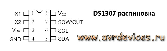
Russian description DS1307.
Hello. To work with the clock, the TWI interface was considered, which we will refer to today. Well, let's start. This watch is TWI compatible, ie the principle of data exchange on the bus will be the same as we considered.
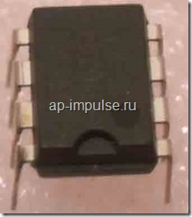
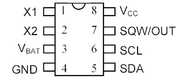
The figure below shows the location of the findings, the description, and the very look of our watches or as we will call them later. RTC (Real-time clock) - real-time clock or time pulse generator. This “device” counts seconds, minutes, hours, day of the month, month, day of the week and year with leap year. The calendar is valid until 2100. I think that's enough for our age :). 
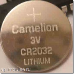
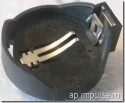
As can be seen from the description, there is an input for emergency power supply from the battery when the external power supply is disconnected. In this mode, the RTC supports only its main purpose — counting time, without external requests. The battery supply voltage should be 2 - 3.5V. The technical description says that with a charge of more than 48 mA / h, at a temperature of 25 degrees Celsius, our scheme will hold for about 10 years. More than necessary. The figure below shows the “tablet” CR2032 and the mount that we will use.
Now go through the external power. The operating voltage of the clock is 5V with a small range of 4.5-5.5V. Voltage from a 3V battery (minimum 2, maximum 3.5V) RTC operation is divided into three voltage modes:
1. Vcc \u003d 5V - read, write, count;
2. Vcc \u003d lower than 1.25 * Vbat, but higher than Vbat + 0.2V - only the battery readout from external power supply.
3. Vcc below Vbat: RTC and RAM switches to battery power. The consumption in the active state of 1.5 mA, from the battery 500-800nA.
Voltage for transmitting / receiving information:
Boolean 0: -0.5V - + 0.8V
Logical 1: 2.2 V - Vcc + 0.3V
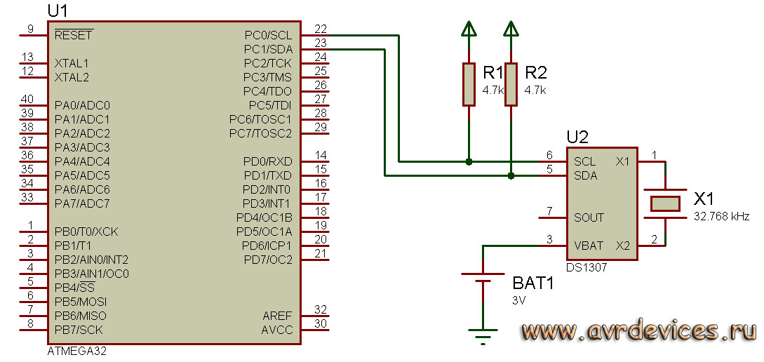
As in previous posts, we try to run it in Proteus. Let's debug the code. And transfer everything to iron. Below is the wiring diagram.

Where SQW / OUT is a clock output that can be programmed to output at 1Hz, 4.096Hz, 8.192Hz and 32.768Hz. Those. can be used for external controller interrupts at intervals of 1 s. Very useful feature. But we do not need. By the way, he is also with an open collector, so a pull-up resistor is needed. 4.7 kΩ nominal.
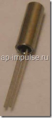
Conclusions X1 and X2 - we connect to them a quartz resonator with a frequency of 32.768 kHz. Or you can use an external clock generator with the same frequency. But at the same time, the output of X1 is connected to the signal, and X2 remains unconnected (hang in the air.).
Well, the findings of SDA and SCL, with whom we met in the last article.
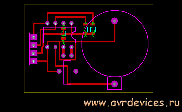
A little dwell on the resonator (figure below). Which can be called the heart of the watch, and on which the accuracy of the course depends. The quality of the resonator itself lies on the manufacturer’s conscience, but for our part, we can reduce the error that external factors introduce if we adhere to the following recommendations for placing a resonator:
2. The width of the route is also possible to do less, to reduce the likelihood of interference from other sources.
3. The contour in the form of a protective ring must be placed around the crystal, which helps to isolate the crystal from noise.
4. Place the conductors in the ring and connect to ground.
5. Solder the resonator to the ground. If the land is bred correctly and there is confidence.
The figure below shows the contour and place of fast ice to the ground.

How to connect figured out. Go ahead - let's figure out how to work with him. The RTC is programmable and has 8 bytes of special registers for its configuration and a non-volatile static memory of 56 bytes. To exchange information, you need a 2-wire data bus, i.e. serial data bus, which we discussed in the last article. So for work we will run through the datasheet. What we need:
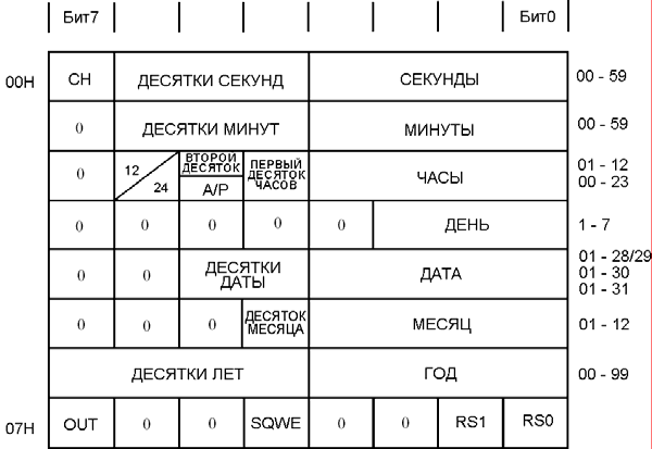
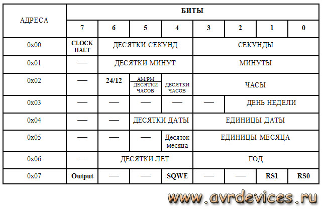
Register table Figure below. The first eight registers are for outputting and programming our watches. When addressing 00H to the 7th bit (CH) and setting it to 0, we start the clock. It should be noted that the configuration of registers can be any, so when you first start it is necessary to configure it to fit your requirements. The remaining seven bits of the unit and tens of seconds.

01H - Minutes.
02H - Clock that is configured:
- Bit 6 - with 1 pin 12 hour format, 0 - 24.
- Bit 5 - at 1 (at 12 hour format) PM, 0-AM
- Bit 5 - (at 24 hours format) is the output of the second ten hours (20-23 hours.)
- Bit4 - the first ten hours, the remaining bits are units of hours.
03H is the day of the week;
04H is the date;
05H - month of the year
06H is a year.
Well, the last register is 07H. This register is control. Where OUT is responsible for controlling the output of SQW / OUT. The following table includes the output.
Out |
SQWE |
SQW / OUT |
1 |
0 |
1 |
0 |
0 |
0 |
SQWE — when this bit is set to 1, pulses are output to the outputs with the specified frequency, which is set with bits RS1 and RS0.
This conclusion is not useful to us in the project. Although for him I made a track on the board. As experiments, it can be somewhere in the future and is applicable, because here you can make an interrupt in 1 second.
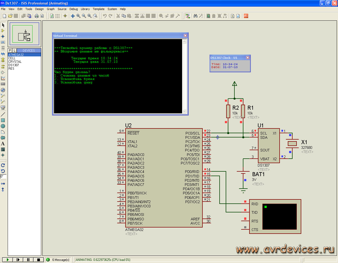
Now having all the necessary information, we will write functions for working with the clock. And also run the project in Proteus . Which will have the following form:

Please note that the resonator in Proteus, you can not connect to the clock (circled in red).
The figure shows the clock terminal, which displays the time, which in turn is tied to the system time. I2C protocol debugger terminal or Twi , which displays the time of sending and receiving a signal, where D0 is the transmitted command, D1 is the receiving. Below I will display screenshots of the terminal with the result of the program.
Program . Having considered the basic clock settings, we will write the initialization function.
/ * The initialization function includes setting the data exchange rate by the formula (in the previous article), setting the divider and turning on the TWI module * /
void init_DS1307 (void)
{
TWBR \u003d 2; / * With a frequency of 1 MHz * /
TWSR \u003d (0<< TWPS1)|(0 << TWPS0); / * Pre divider by 64 * /
TWCR | \u003d (1<< TWEN); / * Enable TWI module * /
}
void write_DS1307 (uint8_t reg, uint8_t time)/ * pass two parameters: the address of the register to which we will apply and the information being transferred * /
{
/ * We form the state of START, setting the bits of the control register * /
TWCR \u003d (1<
/ * Allow the TWEN module to work; Generate a TWSTA start state; Clear TWINT flag * /
/ * We are waiting for the end of the formation of the start condition, i.e. until the flag is set, status code \u003d 08 * /
while (! (TWCR & (1<
/ * Next we fire the address packet (device address). Package contents are loaded into TWDR * /
TWDR \u003d 0xd0; / * 0b1101000 + 0 - address + write bit * /
/ * Reset the flag to transmit information * /
TWCR \u003d (1<
/ * We are waiting for the installation of the flag * /
while (! (TWCR & (1<
/ * pass the register to which we will address * /
TWDR \u003d reg;
TWCR \u003d (1<
while (! (TWCR & (1<
/ * Pass the information to write to the register byte * /
TWDR \u003d time;
TWCR \u003d (1<
while (! (TWCR & (1<
/ * form the STOP state * /
TWCR \u003d (1<
}
In this function, we passed three bytes, a device address, a register address, and a byte of information to write to this register and formed a STOP state.
Remains the last reading function. Below is the reading format.
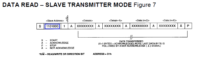
This function transmits the device address byte + write bit, register register byte for setting the pointer to it, meeting the POSTAR condition, transferring the device address byte + read bit, reading the register, the address of which we transmitted earlier.
If we access the clock in the read format, then when the clock is re-accessed, the pointer shifts down one byte including 56 bytes of RAM, from 00H to 3FH. When the last address is reached, the pointer goes to address 00.
/ * Function of reading data from DS1307 * /
uint8_t read_DS1307 (uint8_t reg)/ * Pass the address of the register * /
{
uint8_t time;
/ * form the state START * /
TWCR \u003d (1<
while (! (TWCR & (1<
TWDR \u003d 0xd0; / * Pass address + write bit * /
TWCR \u003d (1<
while (! (TWCR & (1<
TWDR \u003d reg; / * Address of the register * /
TWCR \u003d (1<
while (! (TWCR & (1<
/ * form the state of PER-STAR * /
TWCR \u003d (1<
while (! (TWCR & (1<
TWDR \u003d 0xd1; / * Pass the address + read bit * /
TWCR \u003d (1<
while (! (TWCR & (1<
/ * read data * /
TWCR \u003d (1<
while (! (TWCR & (1<
/ * form the STOP state * /
TWCR \u003d (1<
return time;
}
So above, we wrote three functions that we need to work with the clock. Using these functions, run the program in Proteus. We derive, for example, the date.
#include
#include
uint8_t time;
void init_DS1307 (void);
uint8_t read_DS1307 (uint8_t reg);
void write_DS1307 (uint8_t reg, uint8_t time);
int main (void)
{
DDRC \u003d 0 × 00; / * Set the port as input * /
PORTC \u003d 0xFF; / * We tighten the resistance * /
init_DS1307;
while (1)
{
_delay_ms (50);
read_DS1307 (0 × 04); / * Reading the date register * /
}
}
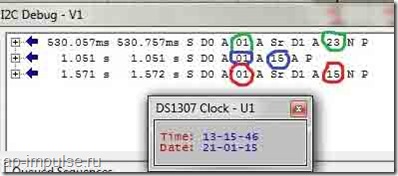
Below is the result of the program reading the date.

In the debugger window I2C
it is clear that the address of the register is first sent to the RTC (green circle), in this case 04, which is responsible for the date of the month, and then the clock sends the answer 21 (red circle).
When we start the clock in the hardware, we will need to record the present time. Below is an example of a minute change program.
while (1)
{
_delay_ms (500);
read_DS1307 (0 × 01); / * Read minute * /
_delay_ms (500);
write_DS1307 (0 × 01, 15); / * We write down the necessary minute * /
_delay_ms (500);
read_DS1307 (0 × 01); / * Read minute * /
}
The figure shows that first the register is addressed to 01, the minute 23 is read. Then we use the write function, and enter the value 15. With the next read function, we have the value 15 on the scoreboard.
Well, the last example of the program is the output of the values \u200b\u200bof all registers.
while (1)
{
delay_ms (500);
read_DS1307 (0 × 00);
_delay_ms (500);
read_DS1307 (0 × 01);
_delay_ms (500);
read_DS1307 (0 × 02);
_delay_ms (500);
read_DS1307 (0 × 03);
_delay_ms (500);
read_DS1307 (0 × 04);
_delay_ms (500);
read_DS1307 (0 × 05);
_delay_ms (500);
read_DS1307 (0 × 06);
_delay_ms (500);
}
In the figure below you can see that the data of 7 registers was derived.
The source code with the project is attached:
(Downloaded: 341 people.)
That's all. We will connect the clock in hardware, we will display the time on the indicator and get acquainted with the binary-decimal format for working with the clock. Bye everyone
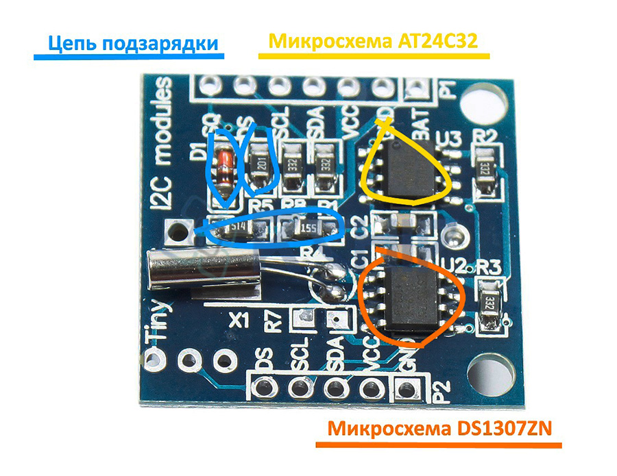
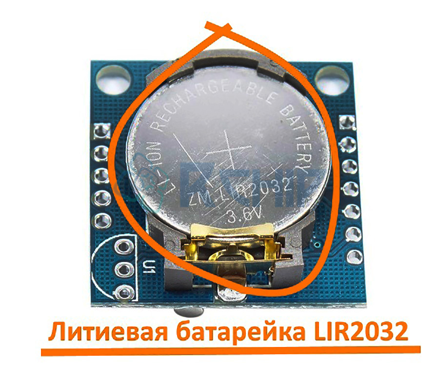
DS1307 is a small module designed to count time. Assembled on the basis of the DS1307ZN chip with the implementation of power from a lithium battery (LIR2032), which allows you to work independently for a long time. Also on the module, a non-volatile EEPROM of 32 KB (AT24C32) is installed. The AT24C32 and DS1307ZN microcircuits are connected by an I2C interface.
Technical specifications
Power supply: 5V
Operating temperature: - 40 ℃ ... + 85 ℃
Memory: 56 bytes (non-volatile)
Battery :
LIR2032 (auto power source detection)
Dimensions: 28mm x 25mm x 8mm
Interface: I2C
General information
Using the DS1307 module is often very justified, for example, when data is rarely read, at intervals of more than a week, using your own controller resources is unreasonable or impossible. Providing uninterrupted power, such as an Arduino board, for a long time is expensive, even when using a battery.
Thanks to its own memory and autonomy, you can record events (for autonomous power supply), for example, temperature changes and so on, the data is stored in memory, they can be read from the module memory. So the DS1307 module is often used when Arduino controllers need to know the exact time, to launch some kind of event, and so on.
On the lower side of the module, the battery holder is almost completely occupied.
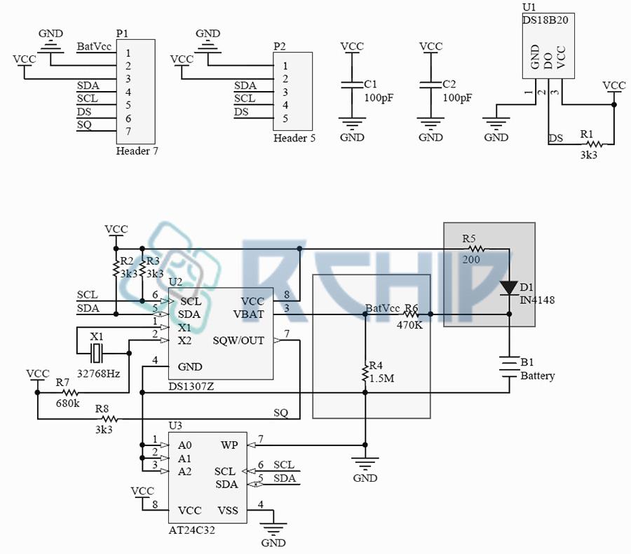
Data is exchanged with other devices via the I2C interface from the SCL and SDA pins. Capacitors C1 and C2 are needed to reduce noise on the power line. To ensure the proper level of the SCL and SDA signals, resistors R2 and R3 are installed (pulled up to the power supply). To test the functionality of the module, the output 7 of the DS1307Z microcircuit is fed with an SQ signal, of rectangular shape with a frequency of 1 Hz. The elements R4, R5, R6, VD1 are needed to charge the lithium battery. Also, there is a seat (U1) on the board, to install the DS18B20 temperature sensor (if necessary, you can solder it), read the readings, you can from the DS pin, which is pulled to the weights, through the resistor R1 with a resistance of 3.3 kΩ. The schematic diagram and the appointment of contacts can be viewed in the figures below.
There are two groups of contacts on the board, 2.54 mm pitch, for convenient connection to the breadboard, I will use the pin connectors, they need to be soldered.
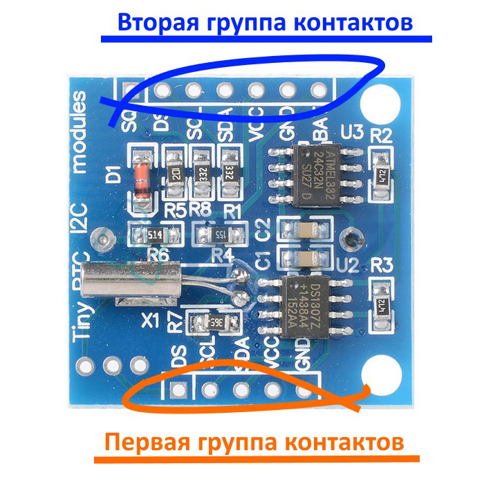
The first group of contacts:
DS: DS18B20 pin (1-wire)
VCC: "+" module power
GND: “-” module power
The second group of contacts:
SQ: 1 MHz input
DS: DS18B20 pin (1-wire)
SCL: clocking line (Serial CLock)
SDA: data line (Serial Dфta)
VCC: "+" module power
GND: “-” module power
BAT:
Battery charging
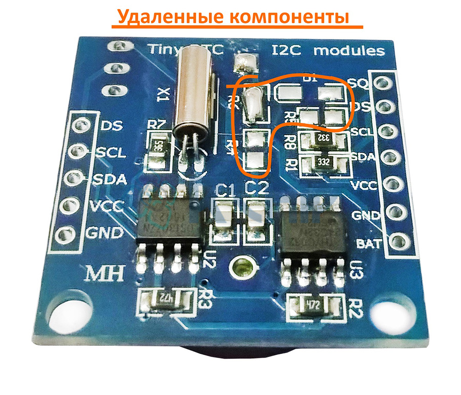
As described your module can charge the battery, it is implemented using components R4, R5, R6 and diode D1. But, this circuit has a drawback, the discharge of the battery occurs through resistors R4 and R6 (as the user ALEXEY noted, not a big one at all). Since the module consumes a small current, you can remove the power circuit, for this we remove R4, R5, R6 and VD1, instead of R6 we put a jumper (after removing the components, you can use a regular CR2032 battery).
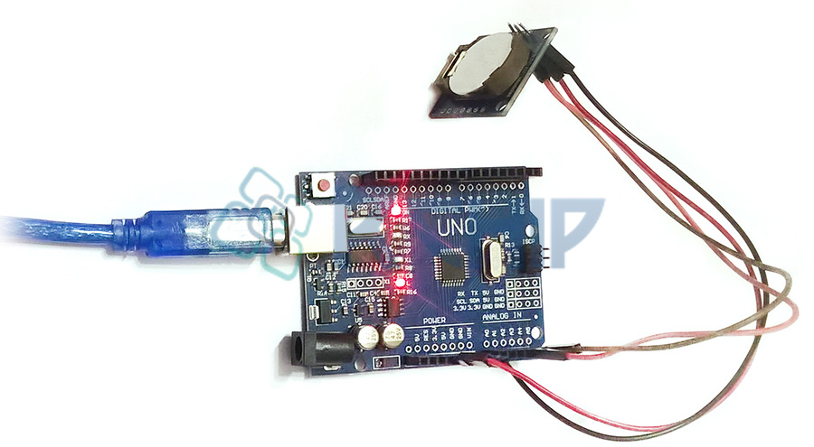
Connection DS1307 to Arduino
Required details:
Arduino UNO R3 x 1 pc.
DuPont wire, 2.54 mm, 20 cm x 1 pc.
USB 2.0 A-B cable x 1 pcs.
Real time clock RTC DS1307 x 1 pcs.
Connection:
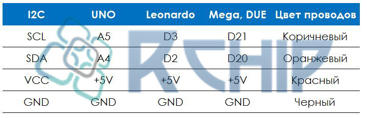
To connect the real-time clock DS1307, it is necessary to solder the pin connectors to the first group of contacts. Next, we connect the SCL wires (DS1307) to pin 4 (Arduino UNO) and SDA (DS1307) to pin 5 (Arduino UNO), it remains to connect the VCC power supply to + 5V and GND to GND. By the way, in various Arduino boards, the I2C interface outputs differ, the purpose of each can be viewed below.
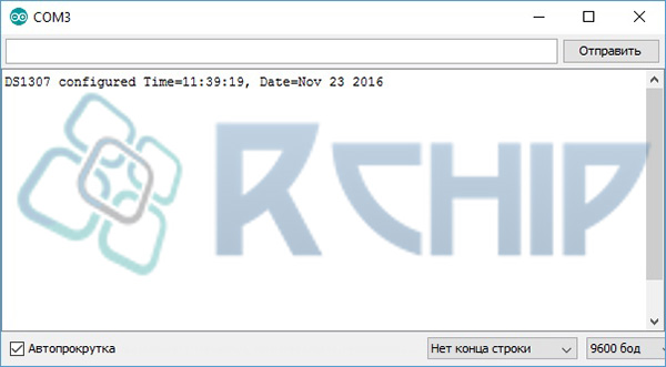
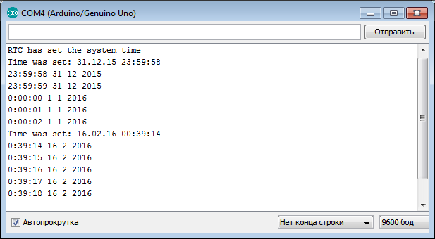
Download and install the DS1307RTC and TimeLib libraries in the Arduino IDE development environment (look at the end of the article). When you first turn on it is necessary to program the time, open an example from the library DS1307RTC “File” -\u003e “Examples” -\u003e “DS1307RTC” -\u003e “SetTime”, or copy the code from below.
// We connect the library DS1307RTC const char * monthName \u003d ("Jan", "Feb", "Mar", "Apr", "May", "Jun", "Jul", "Aug", "Sep", "Oct" , "Nov", "Dec"); tmElements_t tm; void setup () (bool parse \u003d false; bool config \u003d false; // get it; getTate (__ DATE__) && getTime (__ TIME__)) (parse \u003d true; // and configure the RTC with this info if (RTC.write (tm)) (config \u003d true;)) Serial.begin (9600); while (! Serial); // wait for the Arduino Serial Monitor delay (200); if (parse && config) ( Serial.print ("DS1307 configured Time \u003d"); Serial.print (__ TIME__); Serial.print (", Date \u003d"); Serial.println (__ DATE__);) else if (parse) (Serial.println ("DS1307 Communication Error :-( "); Serial.println (" Please check your circuitry ");) else (Serial.print (" Could not parse info from the compiler, Time \u003d \\ ""); Serial.print (__ TIME__); Serial.print ("\\", Date \u003d \\ ""); Serial.print (__ DATE__); Serial.println ("\\" ");)) void loop () () bool getTime (const char * str) (int Hour, Min, Sec; if (sscanf (str, "% d:% d:% d", & Hour, & Min, & Sec)! \u003d 3) return false; tm.Hour \u003d Hour; tm.Minute \u003d Min; tm. Second \u003d Sec; return true;) bool getDat e (const char * str) (char Month; int Day, Year; uint8_t monthIndex; if (sscanf (str, "% s% d% d", Month, & Day, & Year)! \u003d 3) return false; for (monthIndex \u003d 0; monthIndex< 12; monthIndex++) {
if (strcmp(Month, monthName) == 0) break;
}
if (monthIndex >\u003d 12) return false; tm.Day \u003d Day; tm.Month \u003d monthIndex + 1; tm.Year \u003d CalendarYrToTm (Year); return true; )
We load this code into the Arduino controller (the time is taken from the OS), open the “Port Monitoring”
Program
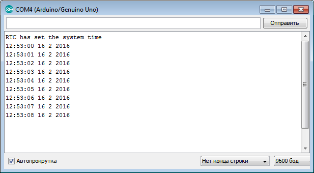
There is another example in the library; you can open it DS1307RTC “File” -\u003e “Examples” -\u003e “DS1307RTC” -\u003e “ReadTest”
/ * Testing was done on Arduino IDE 1.6.12. Testing date 23.11.2016. * / #include // We connect the library Wire #include // We connect the library TimeLib #include // Connect the DS1307RTC library void setup () (Serial.begin (9600); // Set the data transfer rate while (! Serial); // We are waiting for the serial port connection. We need only for Leonardo delay (200); // We are waiting for 200 μs Serial.println ("DS1307RTC Read Test"); // Display the data on the serial port Serial.println ("-------------------"); // Display the data on serial port) void loop () (tmElements_t tm; if (RTC.read (tm)) (Serial.print ("Ok, Time \u003d"); print2digits (tm.Hour); Serial.write (":"); print2digits (tm.Minute); Serial.write (":"); print2digits (tm.Second); Serial.print (", Date (D / M / Y) \u003d"); Serial.print (tm.Day); Serial .write ("/"); Serial.print (tm.Month); Serial.write ("/"); Serial.print (tmYearToCalendar (tm.Year)); Serial.println ();) else (if (RTC .chipPres ent ()) (Serial.println ("The DS1307 is stopped. Please run the SetTime"); Serial.println ("example to initialize the time and begin running."); Serial.println ();) else (Serial. println ("DS1307 read error! Please check the circuitry. "); Serial.println ();) delay (9000);) delay (1000);) void print2digits (int number) (if (number\u003e \u003d 0 && number< 10) {
Serial.write("0");
}
Serial.print(number);
}
DuPont wires, 2.54 mm, 20 cm
Real time clock RTC DS1307
Buy in Samara and the region
Buy controller Arduino UNO R3 in Samara
Buy DuPont wires, 2.54 mm, 20 cm in Samara
Buy real-time clock RTC DS1307 in Samara
The module considered in the article contains at once two microcircuits: DS1307 (real time clock with I2C-interface) and AT24C32 (32K bit EEPROM memory chip).
In this article, we consider the operation of the DS1307 real-time clock chip only.
Main technical characteristics:
Counting the real time in seconds, minutes, hours, dates of the month, months, days of the week and years, taking into account the high year of the current year up to 2100
56 bytes of nonvolatile RAM for data storage
2 wire serial interface
Programmable square pulse generator. It can produce 1 Hz, 4.096 kHz, 8.192 kHz and 32.768 kHz.
Automatic detection of the main power supply disconnection and backup connection
24-hour and 12-hour mode
Consumption is not more than 500 nA when powered from a backup battery at 25 ° C
The microcircuit is available in eight-pin DIP and SOIC packages. Pinout for all the same. The following is a line from the datasheet to complete the picture.
Chip Documentation (datasheet)
Purpose of conclusions:
. X1, X2 - They are used to connect 32.768 kHz quartz resonator
. Vbat - Input for any standard three-volt lithium battery or other power source. For normal operation of the DS1307, it is necessary that the battery voltage be in the range of 2.0 ... 3.5 V. A lithium battery with a capacity of 48 mA / h or more in the absence of power will support the DS1307 in
for more than 10 years at 25 ° C.
. GND - common minus
. Vcc - This is an input of +5 V. When the supply voltage is above 1.25 * VBAT, the device is fully accessible, and data can be read and written. When a 3 V battery is connected to the device, and the Vcc is lower than 1.25 * VBAT, reading and writing are prohibited, but the time count function continues to work. As soon as Vcc drops below VBAT, RAM and RTC switch to VBAT battery power.
. SQW / OUT - Output signal with rectangular pulses.
. SCL - (Serial Clock Input) is used to synchronize data over a serial interface.
. SDA - (Serial Data Input / Output - input / output of serial data) - input / output terminal for a two-wire serial interface.
Work with SQW / OUT pin.
First, consider the structure of the DS1307 registers.
Register Structure of DS1307 Chip
We are interested in the "Managing Register" located at 0x7, because it determines the operation of the SQW / OUT pin.
If the bit SQWE \u003d 1. then the formation of rectangular pulses begins, if SQWE \u003d 0, then the output of the output will be the value of the OUT bit.
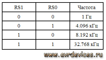
For the pulse frequency correspond bits RS0 and RS1, namely:
RS0
RS1
Frequency
0
0
1 Hz
0
1
4.096 kHz
1
0
8.192 kHz
1
1
32.768 kHz
Let's give an example:
If we need to start the formation of rectangular pulses with a frequency of 1 Hz, then it is necessary in the 0x7 register of the chip, which has the address 0x68 to send byte 00010000 or 0x10 in hexadecimal notation.
With the library Wire.hThis can be done as follows:
Wire .beginTransmission (0x68); Wire .write (0x7); Wire .write (0x10); Wire .endTransmission ();
Connection to Arduino:
The conclusions responsible for the I2C interface on the Arduino boards based on different controllers differ.
Required libraries:
for working with DS1307: http://www.pjrc.com/teensy/td_libs_DS1307RTC.html
for working with time: http://www.pjrc.com/teensy/td_libs_Time.html
Time setting
. Manually in code
The time is set manually in the program code and poured into the Arduino board. This method is not the most accurate. the time to compile and load may take a different time period.
Sample code
#include #include void setup
() {
Serial .begin (9600); while (! Serial
) ; // Only for Leonardo board
// get time from RTC
Serial
// synchronization not deleted else Serial .println ("RTC has set the system time"); // install manually 02/16/2016 12:53 TimeElements te; te.Second \u003d 0; // seconds te.Minute \u003d 53; // minutes te.Hour \u003d 12; // clock te.Day \u003d 16; // day te.Month \u003d 2; // month te.Year \u003d 2016 - 1970; // year in the library is counted from 1970 time_t timeVal \u003d makeTime (te); RTC .set (timeVal); setTime (timeVal); ) void loop () (digitalClockDisplay (); // output time delay (1000);) void digitalClockDisplay () ( Serial
Serial .print (""); Serial .print (day ()); Serial .print (""); Serial .print (month ()); Serial .print (""); Serial .print (year ()); Serial
// display time in ":"
Serial .print (":"); if (digits< 10)
Serial .print ("0"); Serial .print (digits); )
. Setting of "Port Monitor"
A more accurate time setting option. The time is set via the "port monitor" during the operation of the controller.
We open the monitor, enter the data in the right format, look at the reference clock, catch the moment and click "send".
Sample code
// format of indication of the current time "DD.MM.YY hh: mm: ss"
// where DD is the day, MM is the month, YY is the year, hh is the hours, mm is the minutes, ss is the seconds
// YY - from 00 to 99 for 2000–2099 #include #include bool isTimeSet \u003d false; // flag indicating whether the date has already been set void setup
() {
Serial .begin (9600); while (! Serial
) ; // Only for Leonardo board setSyncProvider (RTC .get); // get time from RTC if (timeStatus ()! \u003d timeSet) Serial .println ("Unable to sync with the RTC"); // synchronization not deleted else Serial .println ("RTC has set the system time"); ) void loop () (if ( Serial .available ()) ( // arrived team with time setTimeFromFormatString ( Serial .readStringUntil ("\\ n")); isTimeSet \u003d true; // date was set ) if (isTimeSet) // if the date was set (digitalClockDisplay (); // time output) delay (1000); ) void digitalClockDisplay () ( Serial .print (hour ()); printDigits (minute ()); printDigits (second ()); Serial .print (""); Serial .print (day ()); Serial .print (""); Serial .print (month ()); Serial .print (""); Serial .print (year ()); Serial .println (); ) void printDigits (int digits) ( // display time in ":"
Serial .print (":"); if (digits< 10)
Serial .print ("0"); Serial .print (digits); ) void setTimeFromFormatString (String time) ( //ДД.ММ.ГГ hh: mm: ss int day \u003d time.substring (0, 2) .toInt (); int month \u003d time.substring (3, 5) .toInt (); int year \u003d time.substring (6, 8) .toInt (); int hours \u003d time.substring (9, 11) .toInt (); int minutes \u003d time.substring (12, 14) .toInt (); int seconds \u003d time.substring (15, 17) .toInt (); TimeElements te; te.Second \u003d seconds; te.Minute \u003d minutes; te.Hour \u003d hours; te.Day \u003d day; te.Month \u003d month; te.Year \u003d year + 30; // year in the library is counted from 1970. We want since 2000 time_t timeVal \u003d makeTime (te); RTC .set (timeVal); setTime (timeVal); )
 Buy in Russia
Reviews of these watches on the Internet are the most controversial. Someone says that the watches are wonderful, and someone calls them a wretched hand-made article of Dallas. And here I am, in order to dispel all false rumors, got mikruhu out of the storeroom began to experiment.
Features:
- Very low power consumption. The manufacturer promises 10 years of work hours from one standard battery CR2032
- 56 bytes of memory to store user data. I think not really necessary option, but maybe someone will come in handy.
- Programmable output for clocking external devices. It can produce 1 Hz, 4.096 kHz, 8.192 kHz and 32.768 kHz.
- 24-hour and 12-hour mode
Pinout
The findings of the clock are as follows:
X1, X2 - Conclusions for connecting a quartz resonator at a frequency of 32.768 kHz
VBAT - Conclusion for connection of the 3-volt battery of reserve food
GND - Land
SDA - i2c bus data line
SCL - i2c bus clock line
SQW / OUT - output signal for clocking external devices
VCC - power 5 volts
Connection to the controller
The harness is minimal. It requires 32.768 kHz quartz, a pair of resistors for i2c bus operation and a three volt battery.
Correct wiring board
The accuracy of the course and, in general, the performance of the clock depends on the PCB layout. Dallas in its datasheet recommends that the length of the conductors from the microchip to the quartz resonator be minimized and that these conductors are surrounded by a rectangle connected to the ground. In addition, for reliability, I soldered to the body of the quartz wiring going to the ground and in parallel with the power supply I put a capacitor at 0.1 microfarads.
By the way, it can work without quartz. To do this, X1 is supplied with an external clock signal with a frequency of 32.768 kHz, and X2 remains hanging in the air.
Clock memory organization
This mikruha is endowed with 64 bytes of memory. The first eight bytes are workers. They store the time, date, day of the week. The rest are allocated to the needs of the user. They can be stored for example some settings or something else. Naturally, when the backup power is lost, all the information in this memory is destroyed. All work with the clock (reading and setting the time / date) comes down to reading and writing the right memory cells.
All numbers in memory are stored in binary coded decimal format. This means that two digits can be stored in one byte at once. For example, the number 0x23 - contains the number 2 and the number 3. Each bit is allocated 4 bits. Why is this done? For convenience and save memory. In addition to the time and date, several bits of settings are stored in memory:
- Clock halt - manages the clock. When the bit is set then the clock is set. To start the clock, you must write to this bit 0. After connecting the backup power battery, this bit is set and the clock does not count the time! This must be remembered.
- 24/12
- This bit selects the clock mode. When this bit is one, the 12-hour mode is used. Otherwise, the 24 hour. If the 12-hour mode is used, then the fifth bit shows AM or PM now. If the bit is 1, then it means PM. In 24-hour mode, this bit is used to store tens of hours in conjunction with bit 4.
- Output - controls the state of the leg SQW / OUT. Bit set - on the leg log 1. Reset - on the leg 0. To control in this way, the bit SQWE must be reset.
- SQWE - when the bit is set, rectangular pulses appear on the SQW / OUT foot.
- RS1, RS0 - these bits set the frequency of the pulses. The frequency dependence of the bit combination is in the table below:
Soft
To work with the DS1307 clock, a simple library was written containing the following basic functions:
DS_start - starts the clock. You can also start the clock by setting the time.
DS_stop - stops the clock
DS_set_time -Time setting Before calling the procedure, you need to put it in tmp1 - seconds in tmp2 - minutes and tmp3 hours. Hours in 24-hour format.
DS_get_time: -read time from hours. seconds will be recorded in tmp1, minutes in tmp2, hours in tmp3
DS_get_date: - read the date from the clock. The day will be recorded in tmp1, month in tmp2, year in tmp3
DS_set_date: -date setting. Before calling the procedure, you need to put in tmp1 - day in tmp2 - month and in tmp3-year (last 2 digits)
Procedures for setting / reading the time and date can take / return input data in binary coded decimal format and in decimal format. To select the desired format, you need to comment out or uncomment three lines in each procedure (there are notes in the code about this).
The test program allows you to control the clock via UART (speed 9600, the controller operates at a frequency of 8 MHz). At start-up, the time, date, and an invitation to enter a command from 1 to 3 are immediately displayed. If you select option 1, the time / date is re-read. Option 2 allows you to set the time, and option 3 the date. If you want to try to play with the clock, then the file for the simulation is included in the archive with the source code.
Accuracy
Here a lot depends on the quartz used and the PCB layout. Datashit reports that the quartz capacity should be 12.5 pf. They say that it is best to use quartz from motherboards. To correct the stroke, it is possible to solder a trimmer with a capacitor to the resonator and, with the help of it, change the frequency within a small range. Personally, these hours work for me the second day and are 3 seconds behind. Something tells me that it's in the capacity of quartz, I'll try another one.
Conclusion
Good watch. For amateur use is ideal. Although some write about glitches, but I have not yet encountered.
Lesson 17
Part 1
Real time clock DS1307
We continue programming lessons MK AVR.
And today we will get to know a very good chip. DS1307. This chip is a real time clock (real time clock or RTC).
Also, due to the fact that the microcontroller will communicate with this chip using the interface I2C, we once again actually fix the topic of programming this bus.
This microcircuit is represented by Dallas, here is its pinout and main technical characteristics
Here we see that we have the legs of SDA and SCL, the purpose of which we know very well from. There are also legs X1 and X2 for connecting a quartz resonator at 32768 Hz, power legs - VCC and GND, an output for 1 second pulses or another frequency depending on the settings of certain registers, as well as a positive contact for the battery, which is connected to maintain the clock at the time of disconnecting the main power. We connect the negative contact of this battery to the common power wire.
We also see that this microcircuit is executed in planar and DIP-housings.
This chip can be powered as from 3 volts, and from 5 volts.
Access to this chip via the I2C interface occurs, in principle, also. like the memory chip we used in the last lesson. Of course, there will be some nuances, but more on that later.
Since I have this chip installed in the same module, in which the EEPROM chip is also installed, and we have one bus exchange, the DS1307 chip will know that it is addressed to it, of course, It is different than the EEPROM chip.
Here are diagrams of receiving and transmitting data from the microcircuit.
The address at which we will refer to this chip is highlighted in blue.
Basically. There is a special difference with the EEPROM chip diagrams.
Another difference in circulation will be that the memory addressing will be one-byte, since the memory cells or registers This chip has very little.
This is what the registers are.
The purpose of these registers:
00h - seconds. Seconds are stored in binary coded decimal format. That is, units of seconds are stored in the lower 4 bits, and tens in the older three bits. There is also a SH bit - this is the trigger bit of the chip.
01h - minutes. Stored similarly.
02h - more universal register. Here is a clock. In the four lower bits, there are units of chaos, in the next two more bits - tens, in the next 6 bits - the flag of that afternoon, or until noon, in 7 bits - the storage mode - 12-hour or 24-hour.
03h - day of the week. Stored in the lower 3 bits, the remaining bits are not used.
04h - the day of the month is stored here, also in binary coded decimal format. In the four small bits - units, in the next two older - dozens, the remaining bits are not used.
05h - the number of the month in a year is stored in a binary-decimal format in the same way as the clock.
06h - the year number, and not the full four-digit one, but only the two-digit one. In the lower four bits - units, in the older - tens.
We will use these seven registers. The last register is designed to configure the frequency of the pulses at the pulse output of the chip, this is done in the lower two bits of the register. by default it will be 1 Hz frequency, it is enough for us to blink with a colon, so we will not use these bits. The SOWE and OUT bits are also used to configure and enable the square pulse data generator.
The project for working with this microcircuit was created in the usual way with the name MyClock1307, files related to EEPROM are removed from there, and files are added RTC.c and RTC.h.
#ifndefMAIN_H_
#defineMAIN_H_
#defineF_CPU8000000UL
#include
#include
#include
#include
#include
#include "usart.h"
#include "twi.h"
#include "RTC.h"
#endif/ * MAIN_H_ * /
In the main file MyClock1307.c create global variables for storing the time, date and day of the week, and after that the full content after removing all the excess in it will be like this
#include "main.h"
unsignedcharsec,
min,
hour,
day,
date,
month,
year;
intmain(
void)
{
I2C_Init();
USART_Init(8);
While(1)
{
}
}
From the previous code, only initialization of I2C and USART will remain.
Now we need to somehow start the microcircuit. If the chip is new, or it has never been used, or if someone has changed the value of the CH bit specifically for some purpose, then it has not yet been “walking”.
Well, in general, as soon as we set all the values \u200b\u200bin the registers of the chip, so it will start and our clock will go.
The connection or scheme is also used from the entire past occupation, that is, we will look at the time through the USART bus in the terminal program.
Therefore, in fact, using our knowledge of the previous lesson, we will write the time setting function.
First of all, we, of course, pass the condition START
// Set the time
I2C_StartCondition();
Then we transfer the address with bit of record 0
I2C_StartCondition();
I2C_SendByte(0b11010000);
Let's go to the address 0, which means to the part of the memory where the very first register is located
I2C_SendByte(0b11010000);
I2C_SendByte(0);
// Go to 0x00
Before writing any values \u200b\u200bto the registers of the microcircuit, we recall that we first have to convert numbers to a binary-decimal format that will be convenient for registers. To do this, we go into the file RTC.c and write this function. It will be very easy and does not need to be explained.
unsignedcharRTC_ConvertFromBinDec(
unsignedcharc)
{
unsignedcharch=
((
c/10)<<4)|(
c%10);
returnch;
}
Well, let's also write an inverse type function that converts a number from binary to decimal format to decimal. With the help of it, we, on the contrary, will convert the readings of time into a form convenient for our perception (CPP is a human-friendly interface)
unsignedcharRTC_ConvertFromDec(
unsignedcharc)
{
unsignedcharch=
((
c\u003e\u003e 4) * 10 + (0b00001111 &c));
returnch;
}
Here, everything is also clear, we shift to the right the older tetrad of a byte, multiply it by ten and add the younger tetrad (the older one is masked with zeros)
Write the prototypes of these functions in the file RTC.c
#include "main.h"
unsignedcharRTC_ConvertFromDec(
unsignedcharc);
// convert binary-decimal to decimal
unsignedcharRTC_ConvertFromBinDec(
unsignedcharc);
// convert decimal to binary decimal
We will collect the code, and we will not flash the controller yet. We still need to add the write code to the registers and write in an infinite loop a procedure for reading the time and date and sending it all to USART, and then we’ll completely complete the code by writing the correct time and date values \u200b\u200bto the time setting.
/ * Next we fire the address packet (device address). Package contents are loaded into TWDR * /
TWDR \u003d 0xd0; / * 0b1101000 + 0 - address + write bit * /
/ * Reset the flag to transmit information * /
TWCR \u003d (1<
/ * We are waiting for the installation of the flag * /
while (! (TWCR & (1<
/ * pass the register to which we will address * /
TWDR \u003d reg;
TWCR \u003d (1<
while (! (TWCR & (1<
/ * Pass the information to write to the register byte * /
TWDR \u003d time;
TWCR \u003d (1<
while (! (TWCR & (1<
/ * form the STOP state * /
TWCR \u003d (1<
}
In this function, we passed three bytes, a device address, a register address, and a byte of information to write to this register and formed a STOP state.
Remains the last reading function. Below is the reading format.
This function transmits the device address byte + write bit, register register byte for setting the pointer to it, meeting the POSTAR condition, transferring the device address byte + read bit, reading the register, the address of which we transmitted earlier.
If we access the clock in the read format, then when the clock is re-accessed, the pointer shifts down one byte including 56 bytes of RAM, from 00H to 3FH. When the last address is reached, the pointer goes to address 00.
/ * Function of reading data from DS1307 * /
uint8_t read_DS1307 (uint8_t reg)/ * Pass the address of the register * /
{
uint8_t time;
/ * form the state START * /
TWCR \u003d (1<
while (! (TWCR & (1<
TWDR \u003d 0xd0; / * Pass address + write bit * /
TWCR \u003d (1<
while (! (TWCR & (1<
TWDR \u003d reg; / * Address of the register * /
TWCR \u003d (1<
while (! (TWCR & (1<
/ * form the state of PER-STAR * /
TWCR \u003d (1<
while (! (TWCR & (1<
TWDR \u003d 0xd1; / * Pass the address + read bit * /
TWCR \u003d (1<
while (! (TWCR & (1<
/ * read data * /
TWCR \u003d (1<
while (! (TWCR & (1<
/ * form the STOP state * /
TWCR \u003d (1<
return time;
}
So above, we wrote three functions that we need to work with the clock. Using these functions, run the program in Proteus. We derive, for example, the date.
#include
#include
uint8_t time;
void init_DS1307 (void);
uint8_t read_DS1307 (uint8_t reg);
void write_DS1307 (uint8_t reg, uint8_t time);
int main (void)
{
DDRC \u003d 0 × 00; / * Set the port as input * /
PORTC \u003d 0xFF; / * We tighten the resistance * /
init_DS1307;
while (1)
{
_delay_ms (50);
read_DS1307 (0 × 04); / * Reading the date register * /
}
}
Below is the result of the program reading the date.
In the debugger window I2C
it is clear that the address of the register is first sent to the RTC (green circle), in this case 04, which is responsible for the date of the month, and then the clock sends the answer 21 (red circle).
When we start the clock in the hardware, we will need to record the present time. Below is an example of a minute change program.
while (1)
{
_delay_ms (500);
read_DS1307 (0 × 01); / * Read minute * /
_delay_ms (500);
write_DS1307 (0 × 01, 15); / * We write down the necessary minute * /
_delay_ms (500);
read_DS1307 (0 × 01); / * Read minute * /
}
The figure shows that first the register is addressed to 01, the minute 23 is read. Then we use the write function, and enter the value 15. With the next read function, we have the value 15 on the scoreboard.
Well, the last example of the program is the output of the values \u200b\u200bof all registers.
while (1)
{
delay_ms (500);
read_DS1307 (0 × 00);
_delay_ms (500);
read_DS1307 (0 × 01);
_delay_ms (500);
read_DS1307 (0 × 02);
_delay_ms (500);
read_DS1307 (0 × 03);
_delay_ms (500);
read_DS1307 (0 × 04);
_delay_ms (500);
read_DS1307 (0 × 05);
_delay_ms (500);
read_DS1307 (0 × 06);
_delay_ms (500);
}
In the figure below you can see that the data of 7 registers was derived.
The source code with the project is attached:
(Downloaded: 341 people.)
That's all. We will connect the clock in hardware, we will display the time on the indicator and get acquainted with the binary-decimal format for working with the clock. Bye everyone
DS1307 is a small module designed to count time. Assembled on the basis of the DS1307ZN chip with the implementation of power from a lithium battery (LIR2032), which allows you to work independently for a long time. Also on the module, a non-volatile EEPROM of 32 KB (AT24C32) is installed. The AT24C32 and DS1307ZN microcircuits are connected by an I2C interface.
Technical specifications
Power supply: 5V
Operating temperature: - 40 ℃ ... + 85 ℃
Memory: 56 bytes (non-volatile)
Battery :
LIR2032 (auto power source detection)
Dimensions: 28mm x 25mm x 8mm
Interface: I2C
General information
Using the DS1307 module is often very justified, for example, when data is rarely read, at intervals of more than a week, using your own controller resources is unreasonable or impossible. Providing uninterrupted power, such as an Arduino board, for a long time is expensive, even when using a battery.
Thanks to its own memory and autonomy, you can record events (for autonomous power supply), for example, temperature changes and so on, the data is stored in memory, they can be read from the module memory. So the DS1307 module is often used when Arduino controllers need to know the exact time, to launch some kind of event, and so on.
On the lower side of the module, the battery holder is almost completely occupied.
Data is exchanged with other devices via the I2C interface from the SCL and SDA pins. Capacitors C1 and C2 are needed to reduce noise on the power line. To ensure the proper level of the SCL and SDA signals, resistors R2 and R3 are installed (pulled up to the power supply). To test the functionality of the module, the output 7 of the DS1307Z microcircuit is fed with an SQ signal, of rectangular shape with a frequency of 1 Hz. The elements R4, R5, R6, VD1 are needed to charge the lithium battery. Also, there is a seat (U1) on the board, to install the DS18B20 temperature sensor (if necessary, you can solder it), read the readings, you can from the DS pin, which is pulled to the weights, through the resistor R1 with a resistance of 3.3 kΩ. The schematic diagram and the appointment of contacts can be viewed in the figures below.
There are two groups of contacts on the board, 2.54 mm pitch, for convenient connection to the breadboard, I will use the pin connectors, they need to be soldered.
The first group of contacts:
DS: DS18B20 pin (1-wire)
VCC: "+" module power
GND: “-” module power
The second group of contacts:
SQ: 1 MHz input
DS: DS18B20 pin (1-wire)
SCL: clocking line (Serial CLock)
SDA: data line (Serial Dфta)
VCC: "+" module power
GND: “-” module power
BAT:
Battery charging
As described your module can charge the battery, it is implemented using components R4, R5, R6 and diode D1. But, this circuit has a drawback, the discharge of the battery occurs through resistors R4 and R6 (as the user ALEXEY noted, not a big one at all). Since the module consumes a small current, you can remove the power circuit, for this we remove R4, R5, R6 and VD1, instead of R6 we put a jumper (after removing the components, you can use a regular CR2032 battery).
Connection DS1307 to Arduino
Required details:
Arduino UNO R3 x 1 pc.
DuPont wire, 2.54 mm, 20 cm x 1 pc.
USB 2.0 A-B cable x 1 pcs.
Real time clock RTC DS1307 x 1 pcs.
Connection:
To connect the real-time clock DS1307, it is necessary to solder the pin connectors to the first group of contacts. Next, we connect the SCL wires (DS1307) to pin 4 (Arduino UNO) and SDA (DS1307) to pin 5 (Arduino UNO), it remains to connect the VCC power supply to + 5V and GND to GND. By the way, in various Arduino boards, the I2C interface outputs differ, the purpose of each can be viewed below.
Download and install the DS1307RTC and TimeLib libraries in the Arduino IDE development environment (look at the end of the article). When you first turn on it is necessary to program the time, open an example from the library DS1307RTC “File” -\u003e “Examples” -\u003e “DS1307RTC” -\u003e “SetTime”, or copy the code from below.
// We connect the library DS1307RTC const char * monthName \u003d ("Jan", "Feb", "Mar", "Apr", "May", "Jun", "Jul", "Aug", "Sep", "Oct" , "Nov", "Dec"); tmElements_t tm; void setup () (bool parse \u003d false; bool config \u003d false; // get it; getTate (__ DATE__) && getTime (__ TIME__)) (parse \u003d true; // and configure the RTC with this info if (RTC.write (tm)) (config \u003d true;)) Serial.begin (9600); while (! Serial); // wait for the Arduino Serial Monitor delay (200); if (parse && config) ( Serial.print ("DS1307 configured Time \u003d"); Serial.print (__ TIME__); Serial.print (", Date \u003d"); Serial.println (__ DATE__);) else if (parse) (Serial.println ("DS1307 Communication Error :-( "); Serial.println (" Please check your circuitry ");) else (Serial.print (" Could not parse info from the compiler, Time \u003d \\ ""); Serial.print (__ TIME__); Serial.print ("\\", Date \u003d \\ ""); Serial.print (__ DATE__); Serial.println ("\\" ");)) void loop () () bool getTime (const char * str) (int Hour, Min, Sec; if (sscanf (str, "% d:% d:% d", & Hour, & Min, & Sec)! \u003d 3) return false; tm.Hour \u003d Hour; tm.Minute \u003d Min; tm. Second \u003d Sec; return true;) bool getDat e (const char * str) (char Month; int Day, Year; uint8_t monthIndex; if (sscanf (str, "% s% d% d", Month, & Day, & Year)! \u003d 3) return false; for (monthIndex \u003d 0; monthIndex< 12; monthIndex++) {
if (strcmp(Month, monthName) == 0) break;
}
if (monthIndex >\u003d 12) return false; tm.Day \u003d Day; tm.Month \u003d monthIndex + 1; tm.Year \u003d CalendarYrToTm (Year); return true; )
We load this code into the Arduino controller (the time is taken from the OS), open the “Port Monitoring”
Program
There is another example in the library; you can open it DS1307RTC “File” -\u003e “Examples” -\u003e “DS1307RTC” -\u003e “ReadTest”
/ * Testing was done on Arduino IDE 1.6.12. Testing date 23.11.2016. * / #include // We connect the library Wire #include // We connect the library TimeLib #include // Connect the DS1307RTC library void setup () (Serial.begin (9600); // Set the data transfer rate while (! Serial); // We are waiting for the serial port connection. We need only for Leonardo delay (200); // We are waiting for 200 μs Serial.println ("DS1307RTC Read Test"); // Display the data on the serial port Serial.println ("-------------------"); // Display the data on serial port) void loop () (tmElements_t tm; if (RTC.read (tm)) (Serial.print ("Ok, Time \u003d"); print2digits (tm.Hour); Serial.write (":"); print2digits (tm.Minute); Serial.write (":"); print2digits (tm.Second); Serial.print (", Date (D / M / Y) \u003d"); Serial.print (tm.Day); Serial .write ("/"); Serial.print (tm.Month); Serial.write ("/"); Serial.print (tmYearToCalendar (tm.Year)); Serial.println ();) else (if (RTC .chipPres ent ()) (Serial.println ("The DS1307 is stopped. Please run the SetTime"); Serial.println ("example to initialize the time and begin running."); Serial.println ();) else (Serial. println ("DS1307 read error! Please check the circuitry. "); Serial.println ();) delay (9000);) delay (1000);) void print2digits (int number) (if (number\u003e \u003d 0 && number< 10) {
Serial.write("0");
}
Serial.print(number);
}
DuPont wires, 2.54 mm, 20 cm
Real time clock RTC DS1307
Buy in Samara and the region
Buy controller Arduino UNO R3 in Samara
Buy DuPont wires, 2.54 mm, 20 cm in Samara
Buy real-time clock RTC DS1307 in Samara
The module considered in the article contains at once two microcircuits: DS1307 (real time clock with I2C-interface) and AT24C32 (32K bit EEPROM memory chip).
In this article, we consider the operation of the DS1307 real-time clock chip only.
Main technical characteristics:
Counting the real time in seconds, minutes, hours, dates of the month, months, days of the week and years, taking into account the high year of the current year up to 2100
56 bytes of nonvolatile RAM for data storage
2 wire serial interface
Programmable square pulse generator. It can produce 1 Hz, 4.096 kHz, 8.192 kHz and 32.768 kHz.
Automatic detection of the main power supply disconnection and backup connection
24-hour and 12-hour mode
Consumption is not more than 500 nA when powered from a backup battery at 25 ° C
The microcircuit is available in eight-pin DIP and SOIC packages. Pinout for all the same. The following is a line from the datasheet to complete the picture.
Chip Documentation (datasheet)
Purpose of conclusions:
. X1, X2 - They are used to connect 32.768 kHz quartz resonator
. Vbat - Input for any standard three-volt lithium battery or other power source. For normal operation of the DS1307, it is necessary that the battery voltage be in the range of 2.0 ... 3.5 V. A lithium battery with a capacity of 48 mA / h or more in the absence of power will support the DS1307 in
for more than 10 years at 25 ° C.
. GND - common minus
. Vcc - This is an input of +5 V. When the supply voltage is above 1.25 * VBAT, the device is fully accessible, and data can be read and written. When a 3 V battery is connected to the device, and the Vcc is lower than 1.25 * VBAT, reading and writing are prohibited, but the time count function continues to work. As soon as Vcc drops below VBAT, RAM and RTC switch to VBAT battery power.
. SQW / OUT - Output signal with rectangular pulses.
. SCL - (Serial Clock Input) is used to synchronize data over a serial interface.
. SDA - (Serial Data Input / Output - input / output of serial data) - input / output terminal for a two-wire serial interface.
Work with SQW / OUT pin.
First, consider the structure of the DS1307 registers.
Register Structure of DS1307 Chip
We are interested in the "Managing Register" located at 0x7, because it determines the operation of the SQW / OUT pin.
If the bit SQWE \u003d 1. then the formation of rectangular pulses begins, if SQWE \u003d 0, then the output of the output will be the value of the OUT bit.
For the pulse frequency correspond bits RS0 and RS1, namely:
RS0
RS1
Frequency
0
0
1 Hz
0
1
4.096 kHz
1
0
8.192 kHz
1
1
32.768 kHz
Let's give an example:
If we need to start the formation of rectangular pulses with a frequency of 1 Hz, then it is necessary in the 0x7 register of the chip, which has the address 0x68 to send byte 00010000 or 0x10 in hexadecimal notation.
With the library Wire.hThis can be done as follows:
Wire .beginTransmission (0x68); Wire .write (0x7); Wire .write (0x10); Wire .endTransmission ();
Connection to Arduino:
The conclusions responsible for the I2C interface on the Arduino boards based on different controllers differ.
Required libraries:
for working with DS1307: http://www.pjrc.com/teensy/td_libs_DS1307RTC.html
for working with time: http://www.pjrc.com/teensy/td_libs_Time.html
Time setting
. Manually in code
The time is set manually in the program code and poured into the Arduino board. This method is not the most accurate. the time to compile and load may take a different time period.
Sample code
#include #include void setup
() {
Serial .begin (9600); while (! Serial
) ; // Only for Leonardo board
// get time from RTC
Serial
// synchronization not deleted else Serial .println ("RTC has set the system time"); // install manually 02/16/2016 12:53 TimeElements te; te.Second \u003d 0; // seconds te.Minute \u003d 53; // minutes te.Hour \u003d 12; // clock te.Day \u003d 16; // day te.Month \u003d 2; // month te.Year \u003d 2016 - 1970; // year in the library is counted from 1970 time_t timeVal \u003d makeTime (te); RTC .set (timeVal); setTime (timeVal); ) void loop () (digitalClockDisplay (); // output time delay (1000);) void digitalClockDisplay () ( Serial
Serial .print (""); Serial .print (day ()); Serial .print (""); Serial .print (month ()); Serial .print (""); Serial .print (year ()); Serial
// display time in ":"
Serial .print (":"); if (digits< 10)
Serial .print ("0"); Serial .print (digits); )
. Setting of "Port Monitor"
A more accurate time setting option. The time is set via the "port monitor" during the operation of the controller.
We open the monitor, enter the data in the right format, look at the reference clock, catch the moment and click "send".
Sample code
// format of indication of the current time "DD.MM.YY hh: mm: ss"
// where DD is the day, MM is the month, YY is the year, hh is the hours, mm is the minutes, ss is the seconds
// YY - from 00 to 99 for 2000–2099 #include #include bool isTimeSet \u003d false; // flag indicating whether the date has already been set void setup
() {
Serial .begin (9600); while (! Serial
) ; // Only for Leonardo board setSyncProvider (RTC .get); // get time from RTC if (timeStatus ()! \u003d timeSet) Serial .println ("Unable to sync with the RTC"); // synchronization not deleted else Serial .println ("RTC has set the system time"); ) void loop () (if ( Serial .available ()) ( // arrived team with time setTimeFromFormatString ( Serial .readStringUntil ("\\ n")); isTimeSet \u003d true; // date was set ) if (isTimeSet) // if the date was set (digitalClockDisplay (); // time output) delay (1000); ) void digitalClockDisplay () ( Serial .print (hour ()); printDigits (minute ()); printDigits (second ()); Serial .print (""); Serial .print (day ()); Serial .print (""); Serial .print (month ()); Serial .print (""); Serial .print (year ()); Serial .println (); ) void printDigits (int digits) ( // display time in ":"
Serial .print (":"); if (digits< 10)
Serial .print ("0"); Serial .print (digits); ) void setTimeFromFormatString (String time) ( //ДД.ММ.ГГ hh: mm: ss int day \u003d time.substring (0, 2) .toInt (); int month \u003d time.substring (3, 5) .toInt (); int year \u003d time.substring (6, 8) .toInt (); int hours \u003d time.substring (9, 11) .toInt (); int minutes \u003d time.substring (12, 14) .toInt (); int seconds \u003d time.substring (15, 17) .toInt (); TimeElements te; te.Second \u003d seconds; te.Minute \u003d minutes; te.Hour \u003d hours; te.Day \u003d day; te.Month \u003d month; te.Year \u003d year + 30; // year in the library is counted from 1970. We want since 2000 time_t timeVal \u003d makeTime (te); RTC .set (timeVal); setTime (timeVal); )
Buy in Russia
Reviews of these watches on the Internet are the most controversial. Someone says that the watches are wonderful, and someone calls them a wretched hand-made article of Dallas. And here I am, in order to dispel all false rumors, got mikruhu out of the storeroom began to experiment.
Features:
- Very low power consumption. The manufacturer promises 10 years of work hours from one standard battery CR2032
- 56 bytes of memory to store user data. I think not really necessary option, but maybe someone will come in handy.
- Programmable output for clocking external devices. It can produce 1 Hz, 4.096 kHz, 8.192 kHz and 32.768 kHz.
- 24-hour and 12-hour mode
Pinout
The findings of the clock are as follows:
X1, X2 - Conclusions for connecting a quartz resonator at a frequency of 32.768 kHz
VBAT - Conclusion for connection of the 3-volt battery of reserve food
GND - Land
SDA - i2c bus data line
SCL - i2c bus clock line
SQW / OUT - output signal for clocking external devices
VCC - power 5 volts
Connection to the controller
The harness is minimal. It requires 32.768 kHz quartz, a pair of resistors for i2c bus operation and a three volt battery.
Correct wiring board
The accuracy of the course and, in general, the performance of the clock depends on the PCB layout. Dallas in its datasheet recommends that the length of the conductors from the microchip to the quartz resonator be minimized and that these conductors are surrounded by a rectangle connected to the ground. In addition, for reliability, I soldered to the body of the quartz wiring going to the ground and in parallel with the power supply I put a capacitor at 0.1 microfarads.
By the way, it can work without quartz. To do this, X1 is supplied with an external clock signal with a frequency of 32.768 kHz, and X2 remains hanging in the air.
Clock memory organization
This mikruha is endowed with 64 bytes of memory. The first eight bytes are workers. They store the time, date, day of the week. The rest are allocated to the needs of the user. They can be stored for example some settings or something else. Naturally, when the backup power is lost, all the information in this memory is destroyed. All work with the clock (reading and setting the time / date) comes down to reading and writing the right memory cells.
All numbers in memory are stored in binary coded decimal format. This means that two digits can be stored in one byte at once. For example, the number 0x23 - contains the number 2 and the number 3. Each bit is allocated 4 bits. Why is this done? For convenience and save memory. In addition to the time and date, several bits of settings are stored in memory:
- Clock halt - manages the clock. When the bit is set then the clock is set. To start the clock, you must write to this bit 0. After connecting the backup power battery, this bit is set and the clock does not count the time! This must be remembered.
- 24/12
- This bit selects the clock mode. When this bit is one, the 12-hour mode is used. Otherwise, the 24 hour. If the 12-hour mode is used, then the fifth bit shows AM or PM now. If the bit is 1, then it means PM. In 24-hour mode, this bit is used to store tens of hours in conjunction with bit 4.
- Output - controls the state of the leg SQW / OUT. Bit set - on the leg log 1. Reset - on the leg 0. To control in this way, the bit SQWE must be reset.
- SQWE - when the bit is set, rectangular pulses appear on the SQW / OUT foot.
- RS1, RS0 - these bits set the frequency of the pulses. The frequency dependence of the bit combination is in the table below:
Soft
To work with the DS1307 clock, a simple library was written containing the following basic functions:
DS_start - starts the clock. You can also start the clock by setting the time.
DS_stop - stops the clock
DS_set_time -Time setting Before calling the procedure, you need to put it in tmp1 - seconds in tmp2 - minutes and tmp3 hours. Hours in 24-hour format.
DS_get_time: -read time from hours. seconds will be recorded in tmp1, minutes in tmp2, hours in tmp3
DS_get_date: - read the date from the clock. The day will be recorded in tmp1, month in tmp2, year in tmp3
DS_set_date: -date setting. Before calling the procedure, you need to put in tmp1 - day in tmp2 - month and in tmp3-year (last 2 digits)
Procedures for setting / reading the time and date can take / return input data in binary coded decimal format and in decimal format. To select the desired format, you need to comment out or uncomment three lines in each procedure (there are notes in the code about this).
The test program allows you to control the clock via UART (speed 9600, the controller operates at a frequency of 8 MHz). At start-up, the time, date, and an invitation to enter a command from 1 to 3 are immediately displayed. If you select option 1, the time / date is re-read. Option 2 allows you to set the time, and option 3 the date. If you want to try to play with the clock, then the file for the simulation is included in the archive with the source code.
Accuracy
Here a lot depends on the quartz used and the PCB layout. Datashit reports that the quartz capacity should be 12.5 pf. They say that it is best to use quartz from motherboards. To correct the stroke, it is possible to solder a trimmer with a capacitor to the resonator and, with the help of it, change the frequency within a small range. Personally, these hours work for me the second day and are 3 seconds behind. Something tells me that it's in the capacity of quartz, I'll try another one.
Conclusion
Good watch. For amateur use is ideal. Although some write about glitches, but I have not yet encountered.
Lesson 17
Part 1
Real time clock DS1307
We continue programming lessons MK AVR.
And today we will get to know a very good chip. DS1307. This chip is a real time clock (real time clock or RTC).
Also, due to the fact that the microcontroller will communicate with this chip using the interface I2C, we once again actually fix the topic of programming this bus.
This microcircuit is represented by Dallas, here is its pinout and main technical characteristics
Here we see that we have the legs of SDA and SCL, the purpose of which we know very well from. There are also legs X1 and X2 for connecting a quartz resonator at 32768 Hz, power legs - VCC and GND, an output for 1 second pulses or another frequency depending on the settings of certain registers, as well as a positive contact for the battery, which is connected to maintain the clock at the time of disconnecting the main power. We connect the negative contact of this battery to the common power wire.
We also see that this microcircuit is executed in planar and DIP-housings.
This chip can be powered as from 3 volts, and from 5 volts.
Access to this chip via the I2C interface occurs, in principle, also. like the memory chip we used in the last lesson. Of course, there will be some nuances, but more on that later.
Since I have this chip installed in the same module, in which the EEPROM chip is also installed, and we have one bus exchange, the DS1307 chip will know that it is addressed to it, of course, It is different than the EEPROM chip.
Here are diagrams of receiving and transmitting data from the microcircuit.
The address at which we will refer to this chip is highlighted in blue.
Basically. There is a special difference with the EEPROM chip diagrams.
Another difference in circulation will be that the memory addressing will be one-byte, since the memory cells or registers This chip has very little.
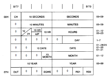
This is what the registers are.
The purpose of these registers:
00h - seconds. Seconds are stored in binary coded decimal format. That is, units of seconds are stored in the lower 4 bits, and tens in the older three bits. There is also a SH bit - this is the trigger bit of the chip.
01h - minutes. Stored similarly.
02h - more universal register. Here is a clock. In the four lower bits, there are units of chaos, in the next two more bits - tens, in the next 6 bits - the flag of that afternoon, or until noon, in 7 bits - the storage mode - 12-hour or 24-hour.
03h - day of the week. Stored in the lower 3 bits, the remaining bits are not used.
04h - the day of the month is stored here, also in binary coded decimal format. In the four small bits - units, in the next two older - dozens, the remaining bits are not used.
05h - the number of the month in a year is stored in a binary-decimal format in the same way as the clock.
06h - the year number, and not the full four-digit one, but only the two-digit one. In the lower four bits - units, in the older - tens.
We will use these seven registers. The last register is designed to configure the frequency of the pulses at the pulse output of the chip, this is done in the lower two bits of the register. by default it will be 1 Hz frequency, it is enough for us to blink with a colon, so we will not use these bits. The SOWE and OUT bits are also used to configure and enable the square pulse data generator.
The project for working with this microcircuit was created in the usual way with the name MyClock1307, files related to EEPROM are removed from there, and files are added RTC.c and RTC.h.
#ifndefMAIN_H_
#defineMAIN_H_
#defineF_CPU8000000UL
#include
#include
#include
#include
#include
#include "usart.h"
#include "twi.h"
#include "RTC.h"
#endif/ * MAIN_H_ * /
In the main file MyClock1307.c create global variables for storing the time, date and day of the week, and after that the full content after removing all the excess in it will be like this
#include "main.h"
unsignedcharsec,
min,
hour,
day,
date,
month,
year;
intmain(
void)
{
I2C_Init();
USART_Init(8);
While(1)
{
}
}
From the previous code, only initialization of I2C and USART will remain.
Now we need to somehow start the microcircuit. If the chip is new, or it has never been used, or if someone has changed the value of the CH bit specifically for some purpose, then it has not yet been “walking”.
Well, in general, as soon as we set all the values \u200b\u200bin the registers of the chip, so it will start and our clock will go.
The connection or scheme is also used from the entire past occupation, that is, we will look at the time through the USART bus in the terminal program.
Therefore, in fact, using our knowledge of the previous lesson, we will write the time setting function.
First of all, we, of course, pass the condition START
// Set the time
I2C_StartCondition();
Then we transfer the address with bit of record 0
I2C_StartCondition();
I2C_SendByte(0b11010000);
Let's go to the address 0, which means to the part of the memory where the very first register is located
I2C_SendByte(0b11010000);
I2C_SendByte(0);
// Go to 0x00
Before writing any values \u200b\u200bto the registers of the microcircuit, we recall that we first have to convert numbers to a binary-decimal format that will be convenient for registers. To do this, we go into the file RTC.c and write this function. It will be very easy and does not need to be explained.
unsignedcharRTC_ConvertFromBinDec(
unsignedcharc)
{
unsignedcharch=
((
c/10)<<4)|(
c%10);
returnch;
}
Well, let's also write an inverse type function that converts a number from binary to decimal format to decimal. With the help of it, we, on the contrary, will convert the readings of time into a form convenient for our perception (CPP is a human-friendly interface)
unsignedcharRTC_ConvertFromDec(
unsignedcharc)
{
unsignedcharch=
((
c\u003e\u003e 4) * 10 + (0b00001111 &c));
returnch;
}
Here, everything is also clear, we shift to the right the older tetrad of a byte, multiply it by ten and add the younger tetrad (the older one is masked with zeros)
Write the prototypes of these functions in the file RTC.c
#include "main.h"
unsignedcharRTC_ConvertFromDec(
unsignedcharc);
// convert binary-decimal to decimal
unsignedcharRTC_ConvertFromBinDec(
unsignedcharc);
// convert decimal to binary decimal
We will collect the code, and we will not flash the controller yet. We still need to add the write code to the registers and write in an infinite loop a procedure for reading the time and date and sending it all to USART, and then we’ll completely complete the code by writing the correct time and date values \u200b\u200bto the time setting.
/ * We are waiting for the installation of the flag * /
while (! (TWCR & (1<
/ * pass the register to which we will address * /
TWDR \u003d reg;
TWCR \u003d (1<
while (! (TWCR & (1<
/ * Pass the information to write to the register byte * /
TWDR \u003d time;
TWCR \u003d (1<
while (! (TWCR & (1<
/ * form the STOP state * /
TWCR \u003d (1<
}
In this function, we passed three bytes, a device address, a register address, and a byte of information to write to this register and formed a STOP state.
Remains the last reading function. Below is the reading format.
This function transmits the device address byte + write bit, register register byte for setting the pointer to it, meeting the POSTAR condition, transferring the device address byte + read bit, reading the register, the address of which we transmitted earlier.
If we access the clock in the read format, then when the clock is re-accessed, the pointer shifts down one byte including 56 bytes of RAM, from 00H to 3FH. When the last address is reached, the pointer goes to address 00.
/ * Function of reading data from DS1307 * /
uint8_t read_DS1307 (uint8_t reg)/ * Pass the address of the register * /
{
uint8_t time;
/ * form the state START * /
TWCR \u003d (1<
while (! (TWCR & (1<
TWDR \u003d 0xd0; / * Pass address + write bit * /
TWCR \u003d (1<
while (! (TWCR & (1<
TWDR \u003d reg; / * Address of the register * /
TWCR \u003d (1<
while (! (TWCR & (1<
/ * form the state of PER-STAR * /
TWCR \u003d (1<
while (! (TWCR & (1<
TWDR \u003d 0xd1; / * Pass the address + read bit * /
TWCR \u003d (1<
while (! (TWCR & (1<
/ * read data * /
TWCR \u003d (1<
while (! (TWCR & (1<
/ * form the STOP state * /
TWCR \u003d (1<
return time;
}
So above, we wrote three functions that we need to work with the clock. Using these functions, run the program in Proteus. We derive, for example, the date.
#include
#include
uint8_t time;
void init_DS1307 (void);
uint8_t read_DS1307 (uint8_t reg);
void write_DS1307 (uint8_t reg, uint8_t time);
int main (void)
{
DDRC \u003d 0 × 00; / * Set the port as input * /
PORTC \u003d 0xFF; / * We tighten the resistance * /
init_DS1307;
while (1)
{
_delay_ms (50);
read_DS1307 (0 × 04); / * Reading the date register * /
}
}
Below is the result of the program reading the date.
In the debugger window I2C
it is clear that the address of the register is first sent to the RTC (green circle), in this case 04, which is responsible for the date of the month, and then the clock sends the answer 21 (red circle).
When we start the clock in the hardware, we will need to record the present time. Below is an example of a minute change program.
while (1)
{
_delay_ms (500);
read_DS1307 (0 × 01); / * Read minute * /
_delay_ms (500);
write_DS1307 (0 × 01, 15); / * We write down the necessary minute * /
_delay_ms (500);
read_DS1307 (0 × 01); / * Read minute * /
}
The figure shows that first the register is addressed to 01, the minute 23 is read. Then we use the write function, and enter the value 15. With the next read function, we have the value 15 on the scoreboard.
Well, the last example of the program is the output of the values \u200b\u200bof all registers.
while (1)
{
delay_ms (500);
read_DS1307 (0 × 00);
_delay_ms (500);
read_DS1307 (0 × 01);
_delay_ms (500);
read_DS1307 (0 × 02);
_delay_ms (500);
read_DS1307 (0 × 03);
_delay_ms (500);
read_DS1307 (0 × 04);
_delay_ms (500);
read_DS1307 (0 × 05);
_delay_ms (500);
read_DS1307 (0 × 06);
_delay_ms (500);
}
In the figure below you can see that the data of 7 registers was derived.
The source code with the project is attached:
(Downloaded: 341 people.)
That's all. We will connect the clock in hardware, we will display the time on the indicator and get acquainted with the binary-decimal format for working with the clock. Bye everyone
DS1307 is a small module designed to count time. Assembled on the basis of the DS1307ZN chip with the implementation of power from a lithium battery (LIR2032), which allows you to work independently for a long time. Also on the module, a non-volatile EEPROM of 32 KB (AT24C32) is installed. The AT24C32 and DS1307ZN microcircuits are connected by an I2C interface.
Technical specifications
Power supply: 5V
Operating temperature: - 40 ℃ ... + 85 ℃
Memory: 56 bytes (non-volatile)
Battery :
LIR2032 (auto power source detection)
Dimensions: 28mm x 25mm x 8mm
Interface: I2C
General information
Using the DS1307 module is often very justified, for example, when data is rarely read, at intervals of more than a week, using your own controller resources is unreasonable or impossible. Providing uninterrupted power, such as an Arduino board, for a long time is expensive, even when using a battery.
Thanks to its own memory and autonomy, you can record events (for autonomous power supply), for example, temperature changes and so on, the data is stored in memory, they can be read from the module memory. So the DS1307 module is often used when Arduino controllers need to know the exact time, to launch some kind of event, and so on.
On the lower side of the module, the battery holder is almost completely occupied.
Data is exchanged with other devices via the I2C interface from the SCL and SDA pins. Capacitors C1 and C2 are needed to reduce noise on the power line. To ensure the proper level of the SCL and SDA signals, resistors R2 and R3 are installed (pulled up to the power supply). To test the functionality of the module, the output 7 of the DS1307Z microcircuit is fed with an SQ signal, of rectangular shape with a frequency of 1 Hz. The elements R4, R5, R6, VD1 are needed to charge the lithium battery. Also, there is a seat (U1) on the board, to install the DS18B20 temperature sensor (if necessary, you can solder it), read the readings, you can from the DS pin, which is pulled to the weights, through the resistor R1 with a resistance of 3.3 kΩ. The schematic diagram and the appointment of contacts can be viewed in the figures below.
There are two groups of contacts on the board, 2.54 mm pitch, for convenient connection to the breadboard, I will use the pin connectors, they need to be soldered.
The first group of contacts:
DS: DS18B20 pin (1-wire)
VCC: "+" module power
GND: “-” module power
The second group of contacts:
SQ: 1 MHz input
DS: DS18B20 pin (1-wire)
SCL: clocking line (Serial CLock)
SDA: data line (Serial Dфta)
VCC: "+" module power
GND: “-” module power
BAT:
Battery charging
As described your module can charge the battery, it is implemented using components R4, R5, R6 and diode D1. But, this circuit has a drawback, the discharge of the battery occurs through resistors R4 and R6 (as the user ALEXEY noted, not a big one at all). Since the module consumes a small current, you can remove the power circuit, for this we remove R4, R5, R6 and VD1, instead of R6 we put a jumper (after removing the components, you can use a regular CR2032 battery).
Connection DS1307 to Arduino
Required details:
Arduino UNO R3 x 1 pc.
DuPont wire, 2.54 mm, 20 cm x 1 pc.
USB 2.0 A-B cable x 1 pcs.
Real time clock RTC DS1307 x 1 pcs.
Connection:
To connect the real-time clock DS1307, it is necessary to solder the pin connectors to the first group of contacts. Next, we connect the SCL wires (DS1307) to pin 4 (Arduino UNO) and SDA (DS1307) to pin 5 (Arduino UNO), it remains to connect the VCC power supply to + 5V and GND to GND. By the way, in various Arduino boards, the I2C interface outputs differ, the purpose of each can be viewed below.
Download and install the DS1307RTC and TimeLib libraries in the Arduino IDE development environment (look at the end of the article). When you first turn on it is necessary to program the time, open an example from the library DS1307RTC “File” -\u003e “Examples” -\u003e “DS1307RTC” -\u003e “SetTime”, or copy the code from below.
// We connect the library DS1307RTC const char * monthName \u003d ("Jan", "Feb", "Mar", "Apr", "May", "Jun", "Jul", "Aug", "Sep", "Oct" , "Nov", "Dec"); tmElements_t tm; void setup () (bool parse \u003d false; bool config \u003d false; // get it; getTate (__ DATE__) && getTime (__ TIME__)) (parse \u003d true; // and configure the RTC with this info if (RTC.write (tm)) (config \u003d true;)) Serial.begin (9600); while (! Serial); // wait for the Arduino Serial Monitor delay (200); if (parse && config) ( Serial.print ("DS1307 configured Time \u003d"); Serial.print (__ TIME__); Serial.print (", Date \u003d"); Serial.println (__ DATE__);) else if (parse) (Serial.println ("DS1307 Communication Error :-( "); Serial.println (" Please check your circuitry ");) else (Serial.print (" Could not parse info from the compiler, Time \u003d \\ ""); Serial.print (__ TIME__); Serial.print ("\\", Date \u003d \\ ""); Serial.print (__ DATE__); Serial.println ("\\" ");)) void loop () () bool getTime (const char * str) (int Hour, Min, Sec; if (sscanf (str, "% d:% d:% d", & Hour, & Min, & Sec)! \u003d 3) return false; tm.Hour \u003d Hour; tm.Minute \u003d Min; tm. Second \u003d Sec; return true;) bool getDat e (const char * str) (char Month; int Day, Year; uint8_t monthIndex; if (sscanf (str, "% s% d% d", Month, & Day, & Year)! \u003d 3) return false; for (monthIndex \u003d 0; monthIndex< 12; monthIndex++) {
if (strcmp(Month, monthName) == 0) break;
}
if (monthIndex >\u003d 12) return false; tm.Day \u003d Day; tm.Month \u003d monthIndex + 1; tm.Year \u003d CalendarYrToTm (Year); return true; )
We load this code into the Arduino controller (the time is taken from the OS), open the “Port Monitoring”
Program
There is another example in the library; you can open it DS1307RTC “File” -\u003e “Examples” -\u003e “DS1307RTC” -\u003e “ReadTest”
/ * Testing was done on Arduino IDE 1.6.12. Testing date 23.11.2016. * / #include // We connect the library Wire #include // We connect the library TimeLib #include // Connect the DS1307RTC library void setup () (Serial.begin (9600); // Set the data transfer rate while (! Serial); // We are waiting for the serial port connection. We need only for Leonardo delay (200); // We are waiting for 200 μs Serial.println ("DS1307RTC Read Test"); // Display the data on the serial port Serial.println ("-------------------"); // Display the data on serial port) void loop () (tmElements_t tm; if (RTC.read (tm)) (Serial.print ("Ok, Time \u003d"); print2digits (tm.Hour); Serial.write (":"); print2digits (tm.Minute); Serial.write (":"); print2digits (tm.Second); Serial.print (", Date (D / M / Y) \u003d"); Serial.print (tm.Day); Serial .write ("/"); Serial.print (tm.Month); Serial.write ("/"); Serial.print (tmYearToCalendar (tm.Year)); Serial.println ();) else (if (RTC .chipPres ent ()) (Serial.println ("The DS1307 is stopped. Please run the SetTime"); Serial.println ("example to initialize the time and begin running."); Serial.println ();) else (Serial. println ("DS1307 read error! Please check the circuitry. "); Serial.println ();) delay (9000);) delay (1000);) void print2digits (int number) (if (number\u003e \u003d 0 && number< 10) {
Serial.write("0");
}
Serial.print(number);
}
DuPont wires, 2.54 mm, 20 cm
Real time clock RTC DS1307
Buy in Samara and the region
Buy controller Arduino UNO R3 in Samara
Buy DuPont wires, 2.54 mm, 20 cm in Samara
Buy real-time clock RTC DS1307 in Samara
The module considered in the article contains at once two microcircuits: DS1307 (real time clock with I2C-interface) and AT24C32 (32K bit EEPROM memory chip).
In this article, we consider the operation of the DS1307 real-time clock chip only.
Main technical characteristics:
Counting the real time in seconds, minutes, hours, dates of the month, months, days of the week and years, taking into account the high year of the current year up to 2100
56 bytes of nonvolatile RAM for data storage
2 wire serial interface
Programmable square pulse generator. It can produce 1 Hz, 4.096 kHz, 8.192 kHz and 32.768 kHz.
Automatic detection of the main power supply disconnection and backup connection
24-hour and 12-hour mode
Consumption is not more than 500 nA when powered from a backup battery at 25 ° C
The microcircuit is available in eight-pin DIP and SOIC packages. Pinout for all the same. The following is a line from the datasheet to complete the picture.
Chip Documentation (datasheet)
Purpose of conclusions:
. X1, X2 - They are used to connect 32.768 kHz quartz resonator
. Vbat - Input for any standard three-volt lithium battery or other power source. For normal operation of the DS1307, it is necessary that the battery voltage be in the range of 2.0 ... 3.5 V. A lithium battery with a capacity of 48 mA / h or more in the absence of power will support the DS1307 in
for more than 10 years at 25 ° C.
. GND - common minus
. Vcc - This is an input of +5 V. When the supply voltage is above 1.25 * VBAT, the device is fully accessible, and data can be read and written. When a 3 V battery is connected to the device, and the Vcc is lower than 1.25 * VBAT, reading and writing are prohibited, but the time count function continues to work. As soon as Vcc drops below VBAT, RAM and RTC switch to VBAT battery power.
. SQW / OUT - Output signal with rectangular pulses.
. SCL - (Serial Clock Input) is used to synchronize data over a serial interface.
. SDA - (Serial Data Input / Output - input / output of serial data) - input / output terminal for a two-wire serial interface.
Work with SQW / OUT pin.
First, consider the structure of the DS1307 registers.
Register Structure of DS1307 Chip
We are interested in the "Managing Register" located at 0x7, because it determines the operation of the SQW / OUT pin.
If the bit SQWE \u003d 1. then the formation of rectangular pulses begins, if SQWE \u003d 0, then the output of the output will be the value of the OUT bit.
For the pulse frequency correspond bits RS0 and RS1, namely:
RS0
RS1
Frequency
0
0
1 Hz
0
1
4.096 kHz
1
0
8.192 kHz
1
1
32.768 kHz
Let's give an example:
If we need to start the formation of rectangular pulses with a frequency of 1 Hz, then it is necessary in the 0x7 register of the chip, which has the address 0x68 to send byte 00010000 or 0x10 in hexadecimal notation.
With the library Wire.hThis can be done as follows:
Wire .beginTransmission (0x68); Wire .write (0x7); Wire .write (0x10); Wire .endTransmission ();
Connection to Arduino:
The conclusions responsible for the I2C interface on the Arduino boards based on different controllers differ.
Required libraries:
for working with DS1307: http://www.pjrc.com/teensy/td_libs_DS1307RTC.html
for working with time: http://www.pjrc.com/teensy/td_libs_Time.html
Time setting
. Manually in code
The time is set manually in the program code and poured into the Arduino board. This method is not the most accurate. the time to compile and load may take a different time period.
Sample code
#include #include void setup
() {
Serial .begin (9600); while (! Serial
) ; // Only for Leonardo board
// get time from RTC
Serial
// synchronization not deleted else Serial .println ("RTC has set the system time"); // install manually 02/16/2016 12:53 TimeElements te; te.Second \u003d 0; // seconds te.Minute \u003d 53; // minutes te.Hour \u003d 12; // clock te.Day \u003d 16; // day te.Month \u003d 2; // month te.Year \u003d 2016 - 1970; // year in the library is counted from 1970 time_t timeVal \u003d makeTime (te); RTC .set (timeVal); setTime (timeVal); ) void loop () (digitalClockDisplay (); // output time delay (1000);) void digitalClockDisplay () ( Serial
Serial .print (""); Serial .print (day ()); Serial .print (""); Serial .print (month ()); Serial .print (""); Serial .print (year ()); Serial
// display time in ":"
Serial .print (":"); if (digits< 10)
Serial .print ("0"); Serial .print (digits); )
. Setting of "Port Monitor"
A more accurate time setting option. The time is set via the "port monitor" during the operation of the controller.
We open the monitor, enter the data in the right format, look at the reference clock, catch the moment and click "send".
Sample code
// format of indication of the current time "DD.MM.YY hh: mm: ss"
// where DD is the day, MM is the month, YY is the year, hh is the hours, mm is the minutes, ss is the seconds
// YY - from 00 to 99 for 2000–2099 #include #include bool isTimeSet \u003d false; // flag indicating whether the date has already been set void setup
() {
Serial .begin (9600); while (! Serial
) ; // Only for Leonardo board setSyncProvider (RTC .get); // get time from RTC if (timeStatus ()! \u003d timeSet) Serial .println ("Unable to sync with the RTC"); // synchronization not deleted else Serial .println ("RTC has set the system time"); ) void loop () (if ( Serial .available ()) ( // arrived team with time setTimeFromFormatString ( Serial .readStringUntil ("\\ n")); isTimeSet \u003d true; // date was set ) if (isTimeSet) // if the date was set (digitalClockDisplay (); // time output) delay (1000); ) void digitalClockDisplay () ( Serial .print (hour ()); printDigits (minute ()); printDigits (second ()); Serial .print (""); Serial .print (day ()); Serial .print (""); Serial .print (month ()); Serial .print (""); Serial .print (year ()); Serial .println (); ) void printDigits (int digits) ( // display time in ":"
Serial .print (":"); if (digits< 10)
Serial .print ("0"); Serial .print (digits); ) void setTimeFromFormatString (String time) ( //ДД.ММ.ГГ hh: mm: ss int day \u003d time.substring (0, 2) .toInt (); int month \u003d time.substring (3, 5) .toInt (); int year \u003d time.substring (6, 8) .toInt (); int hours \u003d time.substring (9, 11) .toInt (); int minutes \u003d time.substring (12, 14) .toInt (); int seconds \u003d time.substring (15, 17) .toInt (); TimeElements te; te.Second \u003d seconds; te.Minute \u003d minutes; te.Hour \u003d hours; te.Day \u003d day; te.Month \u003d month; te.Year \u003d year + 30; // year in the library is counted from 1970. We want since 2000 time_t timeVal \u003d makeTime (te); RTC .set (timeVal); setTime (timeVal); )
Buy in Russia
Reviews of these watches on the Internet are the most controversial. Someone says that the watches are wonderful, and someone calls them a wretched hand-made article of Dallas. And here I am, in order to dispel all false rumors, got mikruhu out of the storeroom began to experiment.
Features:
- Very low power consumption. The manufacturer promises 10 years of work hours from one standard battery CR2032
- 56 bytes of memory to store user data. I think not really necessary option, but maybe someone will come in handy.
- Programmable output for clocking external devices. It can produce 1 Hz, 4.096 kHz, 8.192 kHz and 32.768 kHz.
- 24-hour and 12-hour mode
Pinout
The findings of the clock are as follows:
X1, X2 - Conclusions for connecting a quartz resonator at a frequency of 32.768 kHz
VBAT - Conclusion for connection of the 3-volt battery of reserve food
GND - Land
SDA - i2c bus data line
SCL - i2c bus clock line
SQW / OUT - output signal for clocking external devices
VCC - power 5 volts
Connection to the controller
The harness is minimal. It requires 32.768 kHz quartz, a pair of resistors for i2c bus operation and a three volt battery.
Correct wiring board
The accuracy of the course and, in general, the performance of the clock depends on the PCB layout. Dallas in its datasheet recommends that the length of the conductors from the microchip to the quartz resonator be minimized and that these conductors are surrounded by a rectangle connected to the ground. In addition, for reliability, I soldered to the body of the quartz wiring going to the ground and in parallel with the power supply I put a capacitor at 0.1 microfarads.
By the way, it can work without quartz. To do this, X1 is supplied with an external clock signal with a frequency of 32.768 kHz, and X2 remains hanging in the air.
Clock memory organization
This mikruha is endowed with 64 bytes of memory. The first eight bytes are workers. They store the time, date, day of the week. The rest are allocated to the needs of the user. They can be stored for example some settings or something else. Naturally, when the backup power is lost, all the information in this memory is destroyed. All work with the clock (reading and setting the time / date) comes down to reading and writing the right memory cells.
All numbers in memory are stored in binary coded decimal format. This means that two digits can be stored in one byte at once. For example, the number 0x23 - contains the number 2 and the number 3. Each bit is allocated 4 bits. Why is this done? For convenience and save memory. In addition to the time and date, several bits of settings are stored in memory:
- Clock halt - manages the clock. When the bit is set then the clock is set. To start the clock, you must write to this bit 0. After connecting the backup power battery, this bit is set and the clock does not count the time! This must be remembered.
- 24/12
- This bit selects the clock mode. When this bit is one, the 12-hour mode is used. Otherwise, the 24 hour. If the 12-hour mode is used, then the fifth bit shows AM or PM now. If the bit is 1, then it means PM. In 24-hour mode, this bit is used to store tens of hours in conjunction with bit 4.
- Output - controls the state of the leg SQW / OUT. Bit set - on the leg log 1. Reset - on the leg 0. To control in this way, the bit SQWE must be reset.
- SQWE - when the bit is set, rectangular pulses appear on the SQW / OUT foot.
- RS1, RS0 - these bits set the frequency of the pulses. The frequency dependence of the bit combination is in the table below:
Soft
To work with the DS1307 clock, a simple library was written containing the following basic functions:
DS_start - starts the clock. You can also start the clock by setting the time.
DS_stop - stops the clock
DS_set_time -Time setting Before calling the procedure, you need to put it in tmp1 - seconds in tmp2 - minutes and tmp3 hours. Hours in 24-hour format.
DS_get_time: -read time from hours. seconds will be recorded in tmp1, minutes in tmp2, hours in tmp3
DS_get_date: - read the date from the clock. The day will be recorded in tmp1, month in tmp2, year in tmp3
DS_set_date: -date setting. Before calling the procedure, you need to put in tmp1 - day in tmp2 - month and in tmp3-year (last 2 digits)
Procedures for setting / reading the time and date can take / return input data in binary coded decimal format and in decimal format. To select the desired format, you need to comment out or uncomment three lines in each procedure (there are notes in the code about this).
The test program allows you to control the clock via UART (speed 9600, the controller operates at a frequency of 8 MHz). At start-up, the time, date, and an invitation to enter a command from 1 to 3 are immediately displayed. If you select option 1, the time / date is re-read. Option 2 allows you to set the time, and option 3 the date. If you want to try to play with the clock, then the file for the simulation is included in the archive with the source code.
Accuracy
Here a lot depends on the quartz used and the PCB layout. Datashit reports that the quartz capacity should be 12.5 pf. They say that it is best to use quartz from motherboards. To correct the stroke, it is possible to solder a trimmer with a capacitor to the resonator and, with the help of it, change the frequency within a small range. Personally, these hours work for me the second day and are 3 seconds behind. Something tells me that it's in the capacity of quartz, I'll try another one.
Conclusion
Good watch. For amateur use is ideal. Although some write about glitches, but I have not yet encountered.
Lesson 17
Part 1
Real time clock DS1307
We continue programming lessons MK AVR.
And today we will get to know a very good chip. DS1307. This chip is a real time clock (real time clock or RTC).
Also, due to the fact that the microcontroller will communicate with this chip using the interface I2C, we once again actually fix the topic of programming this bus.
This microcircuit is represented by Dallas, here is its pinout and main technical characteristics
Here we see that we have the legs of SDA and SCL, the purpose of which we know very well from. There are also legs X1 and X2 for connecting a quartz resonator at 32768 Hz, power legs - VCC and GND, an output for 1 second pulses or another frequency depending on the settings of certain registers, as well as a positive contact for the battery, which is connected to maintain the clock at the time of disconnecting the main power. We connect the negative contact of this battery to the common power wire.
We also see that this microcircuit is executed in planar and DIP-housings.
This chip can be powered as from 3 volts, and from 5 volts.
Access to this chip via the I2C interface occurs, in principle, also. like the memory chip we used in the last lesson. Of course, there will be some nuances, but more on that later.
Since I have this chip installed in the same module, in which the EEPROM chip is also installed, and we have one bus exchange, the DS1307 chip will know that it is addressed to it, of course, It is different than the EEPROM chip.
Here are diagrams of receiving and transmitting data from the microcircuit.
The address at which we will refer to this chip is highlighted in blue.
Basically. There is a special difference with the EEPROM chip diagrams.
Another difference in circulation will be that the memory addressing will be one-byte, since the memory cells or registers This chip has very little.
This is what the registers are.
The purpose of these registers:
00h - seconds. Seconds are stored in binary coded decimal format. That is, units of seconds are stored in the lower 4 bits, and tens in the older three bits. There is also a SH bit - this is the trigger bit of the chip.
01h - minutes. Stored similarly.
02h - more universal register. Here is a clock. In the four lower bits, there are units of chaos, in the next two more bits - tens, in the next 6 bits - the flag of that afternoon, or until noon, in 7 bits - the storage mode - 12-hour or 24-hour.
03h - day of the week. Stored in the lower 3 bits, the remaining bits are not used.
04h - the day of the month is stored here, also in binary coded decimal format. In the four small bits - units, in the next two older - dozens, the remaining bits are not used.
05h - the number of the month in a year is stored in a binary-decimal format in the same way as the clock.
06h - the year number, and not the full four-digit one, but only the two-digit one. In the lower four bits - units, in the older - tens.
We will use these seven registers. The last register is designed to configure the frequency of the pulses at the pulse output of the chip, this is done in the lower two bits of the register. by default it will be 1 Hz frequency, it is enough for us to blink with a colon, so we will not use these bits. The SOWE and OUT bits are also used to configure and enable the square pulse data generator.
The project for working with this microcircuit was created in the usual way with the name MyClock1307, files related to EEPROM are removed from there, and files are added RTC.c and RTC.h.
#ifndefMAIN_H_
#defineMAIN_H_
#defineF_CPU8000000UL
#include
#include
#include
#include
#include
#include "usart.h"
#include "twi.h"
#include "RTC.h"
#endif/ * MAIN_H_ * /
In the main file MyClock1307.c create global variables for storing the time, date and day of the week, and after that the full content after removing all the excess in it will be like this
#include "main.h"
unsignedcharsec,
min,
hour,
day,
date,
month,
year;
intmain(
void)
{
I2C_Init();
USART_Init(8);
While(1)
{
}
}
From the previous code, only initialization of I2C and USART will remain.
Now we need to somehow start the microcircuit. If the chip is new, or it has never been used, or if someone has changed the value of the CH bit specifically for some purpose, then it has not yet been “walking”.
Well, in general, as soon as we set all the values \u200b\u200bin the registers of the chip, so it will start and our clock will go.
The connection or scheme is also used from the entire past occupation, that is, we will look at the time through the USART bus in the terminal program.
Therefore, in fact, using our knowledge of the previous lesson, we will write the time setting function.
First of all, we, of course, pass the condition START
// Set the time
I2C_StartCondition();
Then we transfer the address with bit of record 0
I2C_StartCondition();
I2C_SendByte(0b11010000);
Let's go to the address 0, which means to the part of the memory where the very first register is located
I2C_SendByte(0b11010000);
I2C_SendByte(0);
// Go to 0x00
Before writing any values \u200b\u200bto the registers of the microcircuit, we recall that we first have to convert numbers to a binary-decimal format that will be convenient for registers. To do this, we go into the file RTC.c and write this function. It will be very easy and does not need to be explained.
unsignedcharRTC_ConvertFromBinDec(
unsignedcharc)
{
unsignedcharch=
((
c/10)<<4)|(
c%10);
returnch;
}
Well, let's also write an inverse type function that converts a number from binary to decimal format to decimal. With the help of it, we, on the contrary, will convert the readings of time into a form convenient for our perception (CPP is a human-friendly interface)
unsignedcharRTC_ConvertFromDec(
unsignedcharc)
{
unsignedcharch=
((
c\u003e\u003e 4) * 10 + (0b00001111 &c));
returnch;
}
Here, everything is also clear, we shift to the right the older tetrad of a byte, multiply it by ten and add the younger tetrad (the older one is masked with zeros)
Write the prototypes of these functions in the file RTC.c
#include "main.h"
unsignedcharRTC_ConvertFromDec(
unsignedcharc);
// convert binary-decimal to decimal
unsignedcharRTC_ConvertFromBinDec(
unsignedcharc);
// convert decimal to binary decimal
We will collect the code, and we will not flash the controller yet. We still need to add the write code to the registers and write in an infinite loop a procedure for reading the time and date and sending it all to USART, and then we’ll completely complete the code by writing the correct time and date values \u200b\u200bto the time setting.
while (! (TWCR & (1<
/ * Pass the information to write to the register byte * /
TWDR \u003d time;
TWCR \u003d (1<
while (! (TWCR & (1<
/ * form the STOP state * /
TWCR \u003d (1<
}
In this function, we passed three bytes, a device address, a register address, and a byte of information to write to this register and formed a STOP state.
Remains the last reading function. Below is the reading format.
This function transmits the device address byte + write bit, register register byte for setting the pointer to it, meeting the POSTAR condition, transferring the device address byte + read bit, reading the register, the address of which we transmitted earlier.
If we access the clock in the read format, then when the clock is re-accessed, the pointer shifts down one byte including 56 bytes of RAM, from 00H to 3FH. When the last address is reached, the pointer goes to address 00.
/ * Function of reading data from DS1307 * /
uint8_t read_DS1307 (uint8_t reg)/ * Pass the address of the register * /
{
uint8_t time;
/ * form the state START * /
TWCR \u003d (1<
while (! (TWCR & (1<
TWDR \u003d 0xd0; / * Pass address + write bit * /
TWCR \u003d (1<
while (! (TWCR & (1<
TWDR \u003d reg; / * Address of the register * /
TWCR \u003d (1<
while (! (TWCR & (1<
/ * form the state of PER-STAR * /
TWCR \u003d (1<
while (! (TWCR & (1<
TWDR \u003d 0xd1; / * Pass the address + read bit * /
TWCR \u003d (1<
while (! (TWCR & (1<
/ * read data * /
TWCR \u003d (1<
while (! (TWCR & (1<
/ * form the STOP state * /
TWCR \u003d (1<
return time;
}
So above, we wrote three functions that we need to work with the clock. Using these functions, run the program in Proteus. We derive, for example, the date.
#include
#include
uint8_t time;
void init_DS1307 (void);
uint8_t read_DS1307 (uint8_t reg);
void write_DS1307 (uint8_t reg, uint8_t time);
int main (void)
{
DDRC \u003d 0 × 00; / * Set the port as input * /
PORTC \u003d 0xFF; / * We tighten the resistance * /
init_DS1307;
while (1)
{
_delay_ms (50);
read_DS1307 (0 × 04); / * Reading the date register * /
}
}
Below is the result of the program reading the date.
In the debugger window I2C
it is clear that the address of the register is first sent to the RTC (green circle), in this case 04, which is responsible for the date of the month, and then the clock sends the answer 21 (red circle).
When we start the clock in the hardware, we will need to record the present time. Below is an example of a minute change program.
while (1)
{
_delay_ms (500);
read_DS1307 (0 × 01); / * Read minute * /
_delay_ms (500);
write_DS1307 (0 × 01, 15); / * We write down the necessary minute * /
_delay_ms (500);
read_DS1307 (0 × 01); / * Read minute * /
}
The figure shows that first the register is addressed to 01, the minute 23 is read. Then we use the write function, and enter the value 15. With the next read function, we have the value 15 on the scoreboard.
Well, the last example of the program is the output of the values \u200b\u200bof all registers.
while (1)
{
delay_ms (500);
read_DS1307 (0 × 00);
_delay_ms (500);
read_DS1307 (0 × 01);
_delay_ms (500);
read_DS1307 (0 × 02);
_delay_ms (500);
read_DS1307 (0 × 03);
_delay_ms (500);
read_DS1307 (0 × 04);
_delay_ms (500);
read_DS1307 (0 × 05);
_delay_ms (500);
read_DS1307 (0 × 06);
_delay_ms (500);
}
In the figure below you can see that the data of 7 registers was derived.
The source code with the project is attached:
(Downloaded: 341 people.)
That's all. We will connect the clock in hardware, we will display the time on the indicator and get acquainted with the binary-decimal format for working with the clock. Bye everyone
DS1307 is a small module designed to count time. Assembled on the basis of the DS1307ZN chip with the implementation of power from a lithium battery (LIR2032), which allows you to work independently for a long time. Also on the module, a non-volatile EEPROM of 32 KB (AT24C32) is installed. The AT24C32 and DS1307ZN microcircuits are connected by an I2C interface.
Technical specifications
Power supply: 5V
Operating temperature: - 40 ℃ ... + 85 ℃
Memory: 56 bytes (non-volatile)
Battery :
LIR2032 (auto power source detection)
Dimensions: 28mm x 25mm x 8mm
Interface: I2C
General information
Using the DS1307 module is often very justified, for example, when data is rarely read, at intervals of more than a week, using your own controller resources is unreasonable or impossible. Providing uninterrupted power, such as an Arduino board, for a long time is expensive, even when using a battery.
Thanks to its own memory and autonomy, you can record events (for autonomous power supply), for example, temperature changes and so on, the data is stored in memory, they can be read from the module memory. So the DS1307 module is often used when Arduino controllers need to know the exact time, to launch some kind of event, and so on.
On the lower side of the module, the battery holder is almost completely occupied.
Data is exchanged with other devices via the I2C interface from the SCL and SDA pins. Capacitors C1 and C2 are needed to reduce noise on the power line. To ensure the proper level of the SCL and SDA signals, resistors R2 and R3 are installed (pulled up to the power supply). To test the functionality of the module, the output 7 of the DS1307Z microcircuit is fed with an SQ signal, of rectangular shape with a frequency of 1 Hz. The elements R4, R5, R6, VD1 are needed to charge the lithium battery. Also, there is a seat (U1) on the board, to install the DS18B20 temperature sensor (if necessary, you can solder it), read the readings, you can from the DS pin, which is pulled to the weights, through the resistor R1 with a resistance of 3.3 kΩ. The schematic diagram and the appointment of contacts can be viewed in the figures below.
There are two groups of contacts on the board, 2.54 mm pitch, for convenient connection to the breadboard, I will use the pin connectors, they need to be soldered.
The first group of contacts:
DS: DS18B20 pin (1-wire)
VCC: "+" module power
GND: “-” module power
The second group of contacts:
SQ: 1 MHz input
DS: DS18B20 pin (1-wire)
SCL: clocking line (Serial CLock)
SDA: data line (Serial Dфta)
VCC: "+" module power
GND: “-” module power
BAT:
Battery charging
As described your module can charge the battery, it is implemented using components R4, R5, R6 and diode D1. But, this circuit has a drawback, the discharge of the battery occurs through resistors R4 and R6 (as the user ALEXEY noted, not a big one at all). Since the module consumes a small current, you can remove the power circuit, for this we remove R4, R5, R6 and VD1, instead of R6 we put a jumper (after removing the components, you can use a regular CR2032 battery).
Connection DS1307 to Arduino
Required details:
Arduino UNO R3 x 1 pc.
DuPont wire, 2.54 mm, 20 cm x 1 pc.
USB 2.0 A-B cable x 1 pcs.
Real time clock RTC DS1307 x 1 pcs.
Connection:
To connect the real-time clock DS1307, it is necessary to solder the pin connectors to the first group of contacts. Next, we connect the SCL wires (DS1307) to pin 4 (Arduino UNO) and SDA (DS1307) to pin 5 (Arduino UNO), it remains to connect the VCC power supply to + 5V and GND to GND. By the way, in various Arduino boards, the I2C interface outputs differ, the purpose of each can be viewed below.
Download and install the DS1307RTC and TimeLib libraries in the Arduino IDE development environment (look at the end of the article). When you first turn on it is necessary to program the time, open an example from the library DS1307RTC “File” -\u003e “Examples” -\u003e “DS1307RTC” -\u003e “SetTime”, or copy the code from below.
// We connect the library DS1307RTC const char * monthName \u003d ("Jan", "Feb", "Mar", "Apr", "May", "Jun", "Jul", "Aug", "Sep", "Oct" , "Nov", "Dec"); tmElements_t tm; void setup () (bool parse \u003d false; bool config \u003d false; // get it; getTate (__ DATE__) && getTime (__ TIME__)) (parse \u003d true; // and configure the RTC with this info if (RTC.write (tm)) (config \u003d true;)) Serial.begin (9600); while (! Serial); // wait for the Arduino Serial Monitor delay (200); if (parse && config) ( Serial.print ("DS1307 configured Time \u003d"); Serial.print (__ TIME__); Serial.print (", Date \u003d"); Serial.println (__ DATE__);) else if (parse) (Serial.println ("DS1307 Communication Error :-( "); Serial.println (" Please check your circuitry ");) else (Serial.print (" Could not parse info from the compiler, Time \u003d \\ ""); Serial.print (__ TIME__); Serial.print ("\\", Date \u003d \\ ""); Serial.print (__ DATE__); Serial.println ("\\" ");)) void loop () () bool getTime (const char * str) (int Hour, Min, Sec; if (sscanf (str, "% d:% d:% d", & Hour, & Min, & Sec)! \u003d 3) return false; tm.Hour \u003d Hour; tm.Minute \u003d Min; tm. Second \u003d Sec; return true;) bool getDat e (const char * str) (char Month; int Day, Year; uint8_t monthIndex; if (sscanf (str, "% s% d% d", Month, & Day, & Year)! \u003d 3) return false; for (monthIndex \u003d 0; monthIndex< 12; monthIndex++) {
if (strcmp(Month, monthName) == 0) break;
}
if (monthIndex >\u003d 12) return false; tm.Day \u003d Day; tm.Month \u003d monthIndex + 1; tm.Year \u003d CalendarYrToTm (Year); return true; )
We load this code into the Arduino controller (the time is taken from the OS), open the “Port Monitoring”
Program
There is another example in the library; you can open it DS1307RTC “File” -\u003e “Examples” -\u003e “DS1307RTC” -\u003e “ReadTest”
/ * Testing was done on Arduino IDE 1.6.12. Testing date 23.11.2016. * / #include // We connect the library Wire #include // We connect the library TimeLib #include // Connect the DS1307RTC library void setup () (Serial.begin (9600); // Set the data transfer rate while (! Serial); // We are waiting for the serial port connection. We need only for Leonardo delay (200); // We are waiting for 200 μs Serial.println ("DS1307RTC Read Test"); // Display the data on the serial port Serial.println ("-------------------"); // Display the data on serial port) void loop () (tmElements_t tm; if (RTC.read (tm)) (Serial.print ("Ok, Time \u003d"); print2digits (tm.Hour); Serial.write (":"); print2digits (tm.Minute); Serial.write (":"); print2digits (tm.Second); Serial.print (", Date (D / M / Y) \u003d"); Serial.print (tm.Day); Serial .write ("/"); Serial.print (tm.Month); Serial.write ("/"); Serial.print (tmYearToCalendar (tm.Year)); Serial.println ();) else (if (RTC .chipPres ent ()) (Serial.println ("The DS1307 is stopped. Please run the SetTime"); Serial.println ("example to initialize the time and begin running."); Serial.println ();) else (Serial. println ("DS1307 read error! Please check the circuitry. "); Serial.println ();) delay (9000);) delay (1000);) void print2digits (int number) (if (number\u003e \u003d 0 && number< 10) {
Serial.write("0");
}
Serial.print(number);
}
DuPont wires, 2.54 mm, 20 cm
Real time clock RTC DS1307
Buy in Samara and the region
Buy controller Arduino UNO R3 in Samara
Buy DuPont wires, 2.54 mm, 20 cm in Samara
Buy real-time clock RTC DS1307 in Samara
The module considered in the article contains at once two microcircuits: DS1307 (real time clock with I2C-interface) and AT24C32 (32K bit EEPROM memory chip).
In this article, we consider the operation of the DS1307 real-time clock chip only.
Main technical characteristics:
Counting the real time in seconds, minutes, hours, dates of the month, months, days of the week and years, taking into account the high year of the current year up to 2100
56 bytes of nonvolatile RAM for data storage
2 wire serial interface
Programmable square pulse generator. It can produce 1 Hz, 4.096 kHz, 8.192 kHz and 32.768 kHz.
Automatic detection of the main power supply disconnection and backup connection
24-hour and 12-hour mode
Consumption is not more than 500 nA when powered from a backup battery at 25 ° C
The microcircuit is available in eight-pin DIP and SOIC packages. Pinout for all the same. The following is a line from the datasheet to complete the picture.
Chip Documentation (datasheet)
Purpose of conclusions:
. X1, X2 - They are used to connect 32.768 kHz quartz resonator
. Vbat - Input for any standard three-volt lithium battery or other power source. For normal operation of the DS1307, it is necessary that the battery voltage be in the range of 2.0 ... 3.5 V. A lithium battery with a capacity of 48 mA / h or more in the absence of power will support the DS1307 in
for more than 10 years at 25 ° C.
. GND - common minus
. Vcc - This is an input of +5 V. When the supply voltage is above 1.25 * VBAT, the device is fully accessible, and data can be read and written. When a 3 V battery is connected to the device, and the Vcc is lower than 1.25 * VBAT, reading and writing are prohibited, but the time count function continues to work. As soon as Vcc drops below VBAT, RAM and RTC switch to VBAT battery power.
. SQW / OUT - Output signal with rectangular pulses.
. SCL - (Serial Clock Input) is used to synchronize data over a serial interface.
. SDA - (Serial Data Input / Output - input / output of serial data) - input / output terminal for a two-wire serial interface.
Work with SQW / OUT pin.
First, consider the structure of the DS1307 registers.
Register Structure of DS1307 Chip
We are interested in the "Managing Register" located at 0x7, because it determines the operation of the SQW / OUT pin.
If the bit SQWE \u003d 1. then the formation of rectangular pulses begins, if SQWE \u003d 0, then the output of the output will be the value of the OUT bit.
For the pulse frequency correspond bits RS0 and RS1, namely:
RS0
RS1
Frequency
0
0
1 Hz
0
1
4.096 kHz
1
0
8.192 kHz
1
1
32.768 kHz
Let's give an example:
If we need to start the formation of rectangular pulses with a frequency of 1 Hz, then it is necessary in the 0x7 register of the chip, which has the address 0x68 to send byte 00010000 or 0x10 in hexadecimal notation.
With the library Wire.hThis can be done as follows:
Wire .beginTransmission (0x68); Wire .write (0x7); Wire .write (0x10); Wire .endTransmission ();
Connection to Arduino:
The conclusions responsible for the I2C interface on the Arduino boards based on different controllers differ.
Required libraries:
for working with DS1307: http://www.pjrc.com/teensy/td_libs_DS1307RTC.html
for working with time: http://www.pjrc.com/teensy/td_libs_Time.html
Time setting
. Manually in code
The time is set manually in the program code and poured into the Arduino board. This method is not the most accurate. the time to compile and load may take a different time period.
Sample code
#include #include void setup
() {
Serial .begin (9600); while (! Serial
) ; // Only for Leonardo board
// get time from RTC
Serial
// synchronization not deleted else Serial .println ("RTC has set the system time"); // install manually 02/16/2016 12:53 TimeElements te; te.Second \u003d 0; // seconds te.Minute \u003d 53; // minutes te.Hour \u003d 12; // clock te.Day \u003d 16; // day te.Month \u003d 2; // month te.Year \u003d 2016 - 1970; // year in the library is counted from 1970 time_t timeVal \u003d makeTime (te); RTC .set (timeVal); setTime (timeVal); ) void loop () (digitalClockDisplay (); // output time delay (1000);) void digitalClockDisplay () ( Serial
Serial .print (""); Serial .print (day ()); Serial .print (""); Serial .print (month ()); Serial .print (""); Serial .print (year ()); Serial
// display time in ":"
Serial .print (":"); if (digits< 10)
Serial .print ("0"); Serial .print (digits); )
. Setting of "Port Monitor"
A more accurate time setting option. The time is set via the "port monitor" during the operation of the controller.
We open the monitor, enter the data in the right format, look at the reference clock, catch the moment and click "send".
Sample code
// format of indication of the current time "DD.MM.YY hh: mm: ss"
// where DD is the day, MM is the month, YY is the year, hh is the hours, mm is the minutes, ss is the seconds
// YY - from 00 to 99 for 2000–2099 #include #include bool isTimeSet \u003d false; // flag indicating whether the date has already been set void setup
() {
Serial .begin (9600); while (! Serial
) ; // Only for Leonardo board setSyncProvider (RTC .get); // get time from RTC if (timeStatus ()! \u003d timeSet) Serial .println ("Unable to sync with the RTC"); // synchronization not deleted else Serial .println ("RTC has set the system time"); ) void loop () (if ( Serial .available ()) ( // arrived team with time setTimeFromFormatString ( Serial .readStringUntil ("\\ n")); isTimeSet \u003d true; // date was set ) if (isTimeSet) // if the date was set (digitalClockDisplay (); // time output) delay (1000); ) void digitalClockDisplay () ( Serial .print (hour ()); printDigits (minute ()); printDigits (second ()); Serial .print (""); Serial .print (day ()); Serial .print (""); Serial .print (month ()); Serial .print (""); Serial .print (year ()); Serial .println (); ) void printDigits (int digits) ( // display time in ":"
Serial .print (":"); if (digits< 10)
Serial .print ("0"); Serial .print (digits); ) void setTimeFromFormatString (String time) ( //ДД.ММ.ГГ hh: mm: ss int day \u003d time.substring (0, 2) .toInt (); int month \u003d time.substring (3, 5) .toInt (); int year \u003d time.substring (6, 8) .toInt (); int hours \u003d time.substring (9, 11) .toInt (); int minutes \u003d time.substring (12, 14) .toInt (); int seconds \u003d time.substring (15, 17) .toInt (); TimeElements te; te.Second \u003d seconds; te.Minute \u003d minutes; te.Hour \u003d hours; te.Day \u003d day; te.Month \u003d month; te.Year \u003d year + 30; // year in the library is counted from 1970. We want since 2000 time_t timeVal \u003d makeTime (te); RTC .set (timeVal); setTime (timeVal); )
Buy in Russia
Reviews of these watches on the Internet are the most controversial. Someone says that the watches are wonderful, and someone calls them a wretched hand-made article of Dallas. And here I am, in order to dispel all false rumors, got mikruhu out of the storeroom began to experiment.
Features:
- Very low power consumption. The manufacturer promises 10 years of work hours from one standard battery CR2032
- 56 bytes of memory to store user data. I think not really necessary option, but maybe someone will come in handy.
- Programmable output for clocking external devices. It can produce 1 Hz, 4.096 kHz, 8.192 kHz and 32.768 kHz.
- 24-hour and 12-hour mode
Pinout
The findings of the clock are as follows:
X1, X2 - Conclusions for connecting a quartz resonator at a frequency of 32.768 kHz
VBAT - Conclusion for connection of the 3-volt battery of reserve food
GND - Land
SDA - i2c bus data line
SCL - i2c bus clock line
SQW / OUT - output signal for clocking external devices
VCC - power 5 volts
Connection to the controller
The harness is minimal. It requires 32.768 kHz quartz, a pair of resistors for i2c bus operation and a three volt battery.
Correct wiring board
The accuracy of the course and, in general, the performance of the clock depends on the PCB layout. Dallas in its datasheet recommends that the length of the conductors from the microchip to the quartz resonator be minimized and that these conductors are surrounded by a rectangle connected to the ground. In addition, for reliability, I soldered to the body of the quartz wiring going to the ground and in parallel with the power supply I put a capacitor at 0.1 microfarads.
By the way, it can work without quartz. To do this, X1 is supplied with an external clock signal with a frequency of 32.768 kHz, and X2 remains hanging in the air.
Clock memory organization
This mikruha is endowed with 64 bytes of memory. The first eight bytes are workers. They store the time, date, day of the week. The rest are allocated to the needs of the user. They can be stored for example some settings or something else. Naturally, when the backup power is lost, all the information in this memory is destroyed. All work with the clock (reading and setting the time / date) comes down to reading and writing the right memory cells.
All numbers in memory are stored in binary coded decimal format. This means that two digits can be stored in one byte at once. For example, the number 0x23 - contains the number 2 and the number 3. Each bit is allocated 4 bits. Why is this done? For convenience and save memory. In addition to the time and date, several bits of settings are stored in memory:
- Clock halt - manages the clock. When the bit is set then the clock is set. To start the clock, you must write to this bit 0. After connecting the backup power battery, this bit is set and the clock does not count the time! This must be remembered.
- 24/12
- This bit selects the clock mode. When this bit is one, the 12-hour mode is used. Otherwise, the 24 hour. If the 12-hour mode is used, then the fifth bit shows AM or PM now. If the bit is 1, then it means PM. In 24-hour mode, this bit is used to store tens of hours in conjunction with bit 4.
- Output - controls the state of the leg SQW / OUT. Bit set - on the leg log 1. Reset - on the leg 0. To control in this way, the bit SQWE must be reset.
- SQWE - when the bit is set, rectangular pulses appear on the SQW / OUT foot.
- RS1, RS0 - these bits set the frequency of the pulses. The frequency dependence of the bit combination is in the table below:
Soft
To work with the DS1307 clock, a simple library was written containing the following basic functions:
DS_start - starts the clock. You can also start the clock by setting the time.
DS_stop - stops the clock
DS_set_time -Time setting Before calling the procedure, you need to put it in tmp1 - seconds in tmp2 - minutes and tmp3 hours. Hours in 24-hour format.
DS_get_time: -read time from hours. seconds will be recorded in tmp1, minutes in tmp2, hours in tmp3
DS_get_date: - read the date from the clock. The day will be recorded in tmp1, month in tmp2, year in tmp3
DS_set_date: -date setting. Before calling the procedure, you need to put in tmp1 - day in tmp2 - month and in tmp3-year (last 2 digits)
Procedures for setting / reading the time and date can take / return input data in binary coded decimal format and in decimal format. To select the desired format, you need to comment out or uncomment three lines in each procedure (there are notes in the code about this).
The test program allows you to control the clock via UART (speed 9600, the controller operates at a frequency of 8 MHz). At start-up, the time, date, and an invitation to enter a command from 1 to 3 are immediately displayed. If you select option 1, the time / date is re-read. Option 2 allows you to set the time, and option 3 the date. If you want to try to play with the clock, then the file for the simulation is included in the archive with the source code.
Accuracy
Here a lot depends on the quartz used and the PCB layout. Datashit reports that the quartz capacity should be 12.5 pf. They say that it is best to use quartz from motherboards. To correct the stroke, it is possible to solder a trimmer with a capacitor to the resonator and, with the help of it, change the frequency within a small range. Personally, these hours work for me the second day and are 3 seconds behind. Something tells me that it's in the capacity of quartz, I'll try another one.
Conclusion
Good watch. For amateur use is ideal. Although some write about glitches, but I have not yet encountered.
Lesson 17
Part 1
Real time clock DS1307
We continue programming lessons MK AVR.
And today we will get to know a very good chip. DS1307. This chip is a real time clock (real time clock or RTC).
Also, due to the fact that the microcontroller will communicate with this chip using the interface I2C, we once again actually fix the topic of programming this bus.
This microcircuit is represented by Dallas, here is its pinout and main technical characteristics
Here we see that we have the legs of SDA and SCL, the purpose of which we know very well from. There are also legs X1 and X2 for connecting a quartz resonator at 32768 Hz, power legs - VCC and GND, an output for 1 second pulses or another frequency depending on the settings of certain registers, as well as a positive contact for the battery, which is connected to maintain the clock at the time of disconnecting the main power. We connect the negative contact of this battery to the common power wire.
We also see that this microcircuit is executed in planar and DIP-housings.
This chip can be powered as from 3 volts, and from 5 volts.
Access to this chip via the I2C interface occurs, in principle, also. like the memory chip we used in the last lesson. Of course, there will be some nuances, but more on that later.
Since I have this chip installed in the same module, in which the EEPROM chip is also installed, and we have one bus exchange, the DS1307 chip will know that it is addressed to it, of course, It is different than the EEPROM chip.
Here are diagrams of receiving and transmitting data from the microcircuit.
The address at which we will refer to this chip is highlighted in blue.
Basically. There is a special difference with the EEPROM chip diagrams.
Another difference in circulation will be that the memory addressing will be one-byte, since the memory cells or registers This chip has very little.
This is what the registers are.
The purpose of these registers:
00h - seconds. Seconds are stored in binary coded decimal format. That is, units of seconds are stored in the lower 4 bits, and tens in the older three bits. There is also a SH bit - this is the trigger bit of the chip.
01h - minutes. Stored similarly.
02h - more universal register. Here is a clock. In the four lower bits, there are units of chaos, in the next two more bits - tens, in the next 6 bits - the flag of that afternoon, or until noon, in 7 bits - the storage mode - 12-hour or 24-hour.
03h - day of the week. Stored in the lower 3 bits, the remaining bits are not used.
04h - the day of the month is stored here, also in binary coded decimal format. In the four small bits - units, in the next two older - dozens, the remaining bits are not used.
05h - the number of the month in a year is stored in a binary-decimal format in the same way as the clock.
06h - the year number, and not the full four-digit one, but only the two-digit one. In the lower four bits - units, in the older - tens.
We will use these seven registers. The last register is designed to configure the frequency of the pulses at the pulse output of the chip, this is done in the lower two bits of the register. by default it will be 1 Hz frequency, it is enough for us to blink with a colon, so we will not use these bits. The SOWE and OUT bits are also used to configure and enable the square pulse data generator.
The project for working with this microcircuit was created in the usual way with the name MyClock1307, files related to EEPROM are removed from there, and files are added RTC.c and RTC.h.
#ifndefMAIN_H_
#defineMAIN_H_
#defineF_CPU8000000UL
#include
#include
#include
#include
#include
#include "usart.h"
#include "twi.h"
#include "RTC.h"
#endif/ * MAIN_H_ * /
In the main file MyClock1307.c create global variables for storing the time, date and day of the week, and after that the full content after removing all the excess in it will be like this
#include "main.h"
unsignedcharsec,
min,
hour,
day,
date,
month,
year;
intmain(
void)
{
I2C_Init();
USART_Init(8);
While(1)
{
}
}
From the previous code, only initialization of I2C and USART will remain.
Now we need to somehow start the microcircuit. If the chip is new, or it has never been used, or if someone has changed the value of the CH bit specifically for some purpose, then it has not yet been “walking”.
Well, in general, as soon as we set all the values \u200b\u200bin the registers of the chip, so it will start and our clock will go.
The connection or scheme is also used from the entire past occupation, that is, we will look at the time through the USART bus in the terminal program.
Therefore, in fact, using our knowledge of the previous lesson, we will write the time setting function.
First of all, we, of course, pass the condition START
// Set the time
I2C_StartCondition();
Then we transfer the address with bit of record 0
I2C_StartCondition();
I2C_SendByte(0b11010000);
Let's go to the address 0, which means to the part of the memory where the very first register is located
I2C_SendByte(0b11010000);
I2C_SendByte(0);
// Go to 0x00
Before writing any values \u200b\u200bto the registers of the microcircuit, we recall that we first have to convert numbers to a binary-decimal format that will be convenient for registers. To do this, we go into the file RTC.c and write this function. It will be very easy and does not need to be explained.
unsignedcharRTC_ConvertFromBinDec(
unsignedcharc)
{
unsignedcharch=
((
c/10)<<4)|(
c%10);
returnch;
}
Well, let's also write an inverse type function that converts a number from binary to decimal format to decimal. With the help of it, we, on the contrary, will convert the readings of time into a form convenient for our perception (CPP is a human-friendly interface)
unsignedcharRTC_ConvertFromDec(
unsignedcharc)
{
unsignedcharch=
((
c\u003e\u003e 4) * 10 + (0b00001111 &c));
returnch;
}
Here, everything is also clear, we shift to the right the older tetrad of a byte, multiply it by ten and add the younger tetrad (the older one is masked with zeros)
Write the prototypes of these functions in the file RTC.c
#include "main.h"
unsignedcharRTC_ConvertFromDec(
unsignedcharc);
// convert binary-decimal to decimal
unsignedcharRTC_ConvertFromBinDec(
unsignedcharc);
// convert decimal to binary decimal
We will collect the code, and we will not flash the controller yet. We still need to add the write code to the registers and write in an infinite loop a procedure for reading the time and date and sending it all to USART, and then we’ll completely complete the code by writing the correct time and date values \u200b\u200bto the time setting.
while (! (TWCR & (1<
/ * form the STOP state * /
TWCR \u003d (1<
}
In this function, we passed three bytes, a device address, a register address, and a byte of information to write to this register and formed a STOP state.
Remains the last reading function. Below is the reading format.
This function transmits the device address byte + write bit, register register byte for setting the pointer to it, meeting the POSTAR condition, transferring the device address byte + read bit, reading the register, the address of which we transmitted earlier.
If we access the clock in the read format, then when the clock is re-accessed, the pointer shifts down one byte including 56 bytes of RAM, from 00H to 3FH. When the last address is reached, the pointer goes to address 00.
/ * Function of reading data from DS1307 * /
uint8_t read_DS1307 (uint8_t reg)/ * Pass the address of the register * /
{
uint8_t time;
/ * form the state START * /
TWCR \u003d (1<
while (! (TWCR & (1<
TWDR \u003d 0xd0; / * Pass address + write bit * /
TWCR \u003d (1<
while (! (TWCR & (1<
TWDR \u003d reg; / * Address of the register * /
TWCR \u003d (1<
while (! (TWCR & (1<
/ * form the state of PER-STAR * /
TWCR \u003d (1<
while (! (TWCR & (1<
TWDR \u003d 0xd1; / * Pass the address + read bit * /
TWCR \u003d (1<
while (! (TWCR & (1<
/ * read data * /
TWCR \u003d (1<
while (! (TWCR & (1<
/ * form the STOP state * /
TWCR \u003d (1<
return time;
}
So above, we wrote three functions that we need to work with the clock. Using these functions, run the program in Proteus. We derive, for example, the date.
#include
#include
uint8_t time;
void init_DS1307 (void);
uint8_t read_DS1307 (uint8_t reg);
void write_DS1307 (uint8_t reg, uint8_t time);
int main (void)
{
DDRC \u003d 0 × 00; / * Set the port as input * /
PORTC \u003d 0xFF; / * We tighten the resistance * /
init_DS1307;
while (1)
{
_delay_ms (50);
read_DS1307 (0 × 04); / * Reading the date register * /
}
}
Below is the result of the program reading the date.
In the debugger window I2C
it is clear that the address of the register is first sent to the RTC (green circle), in this case 04, which is responsible for the date of the month, and then the clock sends the answer 21 (red circle).
When we start the clock in the hardware, we will need to record the present time. Below is an example of a minute change program.
while (1)
{
_delay_ms (500);
read_DS1307 (0 × 01); / * Read minute * /
_delay_ms (500);
write_DS1307 (0 × 01, 15); / * We write down the necessary minute * /
_delay_ms (500);
read_DS1307 (0 × 01); / * Read minute * /
}
The figure shows that first the register is addressed to 01, the minute 23 is read. Then we use the write function, and enter the value 15. With the next read function, we have the value 15 on the scoreboard.
Well, the last example of the program is the output of the values \u200b\u200bof all registers.
while (1)
{
delay_ms (500);
read_DS1307 (0 × 00);
_delay_ms (500);
read_DS1307 (0 × 01);
_delay_ms (500);
read_DS1307 (0 × 02);
_delay_ms (500);
read_DS1307 (0 × 03);
_delay_ms (500);
read_DS1307 (0 × 04);
_delay_ms (500);
read_DS1307 (0 × 05);
_delay_ms (500);
read_DS1307 (0 × 06);
_delay_ms (500);
}
In the figure below you can see that the data of 7 registers was derived.
The source code with the project is attached:
(Downloaded: 341 people.)
That's all. We will connect the clock in hardware, we will display the time on the indicator and get acquainted with the binary-decimal format for working with the clock. Bye everyone
DS1307 is a small module designed to count time. Assembled on the basis of the DS1307ZN chip with the implementation of power from a lithium battery (LIR2032), which allows you to work independently for a long time. Also on the module, a non-volatile EEPROM of 32 KB (AT24C32) is installed. The AT24C32 and DS1307ZN microcircuits are connected by an I2C interface.
Technical specifications
Power supply: 5V
Operating temperature: - 40 ℃ ... + 85 ℃
Memory: 56 bytes (non-volatile)
Battery :
LIR2032 (auto power source detection)
Dimensions: 28mm x 25mm x 8mm
Interface: I2C
General information
Using the DS1307 module is often very justified, for example, when data is rarely read, at intervals of more than a week, using your own controller resources is unreasonable or impossible. Providing uninterrupted power, such as an Arduino board, for a long time is expensive, even when using a battery.
Thanks to its own memory and autonomy, you can record events (for autonomous power supply), for example, temperature changes and so on, the data is stored in memory, they can be read from the module memory. So the DS1307 module is often used when Arduino controllers need to know the exact time, to launch some kind of event, and so on.
On the lower side of the module, the battery holder is almost completely occupied.
Data is exchanged with other devices via the I2C interface from the SCL and SDA pins. Capacitors C1 and C2 are needed to reduce noise on the power line. To ensure the proper level of the SCL and SDA signals, resistors R2 and R3 are installed (pulled up to the power supply). To test the functionality of the module, the output 7 of the DS1307Z microcircuit is fed with an SQ signal, of rectangular shape with a frequency of 1 Hz. The elements R4, R5, R6, VD1 are needed to charge the lithium battery. Also, there is a seat (U1) on the board, to install the DS18B20 temperature sensor (if necessary, you can solder it), read the readings, you can from the DS pin, which is pulled to the weights, through the resistor R1 with a resistance of 3.3 kΩ. The schematic diagram and the appointment of contacts can be viewed in the figures below.
There are two groups of contacts on the board, 2.54 mm pitch, for convenient connection to the breadboard, I will use the pin connectors, they need to be soldered.
The first group of contacts:
DS: DS18B20 pin (1-wire)
VCC: "+" module power
GND: “-” module power
The second group of contacts:
SQ: 1 MHz input
DS: DS18B20 pin (1-wire)
SCL: clocking line (Serial CLock)
SDA: data line (Serial Dфta)
VCC: "+" module power
GND: “-” module power
BAT:
Battery charging
As described your module can charge the battery, it is implemented using components R4, R5, R6 and diode D1. But, this circuit has a drawback, the discharge of the battery occurs through resistors R4 and R6 (as the user ALEXEY noted, not a big one at all). Since the module consumes a small current, you can remove the power circuit, for this we remove R4, R5, R6 and VD1, instead of R6 we put a jumper (after removing the components, you can use a regular CR2032 battery).
Connection DS1307 to Arduino
Required details:
Arduino UNO R3 x 1 pc.
DuPont wire, 2.54 mm, 20 cm x 1 pc.
USB 2.0 A-B cable x 1 pcs.
Real time clock RTC DS1307 x 1 pcs.
Connection:
To connect the real-time clock DS1307, it is necessary to solder the pin connectors to the first group of contacts. Next, we connect the SCL wires (DS1307) to pin 4 (Arduino UNO) and SDA (DS1307) to pin 5 (Arduino UNO), it remains to connect the VCC power supply to + 5V and GND to GND. By the way, in various Arduino boards, the I2C interface outputs differ, the purpose of each can be viewed below.
Download and install the DS1307RTC and TimeLib libraries in the Arduino IDE development environment (look at the end of the article). When you first turn on it is necessary to program the time, open an example from the library DS1307RTC “File” -\u003e “Examples” -\u003e “DS1307RTC” -\u003e “SetTime”, or copy the code from below.
// We connect the library DS1307RTC const char * monthName \u003d ("Jan", "Feb", "Mar", "Apr", "May", "Jun", "Jul", "Aug", "Sep", "Oct" , "Nov", "Dec"); tmElements_t tm; void setup () (bool parse \u003d false; bool config \u003d false; // get it; getTate (__ DATE__) && getTime (__ TIME__)) (parse \u003d true; // and configure the RTC with this info if (RTC.write (tm)) (config \u003d true;)) Serial.begin (9600); while (! Serial); // wait for the Arduino Serial Monitor delay (200); if (parse && config) ( Serial.print ("DS1307 configured Time \u003d"); Serial.print (__ TIME__); Serial.print (", Date \u003d"); Serial.println (__ DATE__);) else if (parse) (Serial.println ("DS1307 Communication Error :-( "); Serial.println (" Please check your circuitry ");) else (Serial.print (" Could not parse info from the compiler, Time \u003d \\ ""); Serial.print (__ TIME__); Serial.print ("\\", Date \u003d \\ ""); Serial.print (__ DATE__); Serial.println ("\\" ");)) void loop () () bool getTime (const char * str) (int Hour, Min, Sec; if (sscanf (str, "% d:% d:% d", & Hour, & Min, & Sec)! \u003d 3) return false; tm.Hour \u003d Hour; tm.Minute \u003d Min; tm. Second \u003d Sec; return true;) bool getDat e (const char * str) (char Month; int Day, Year; uint8_t monthIndex; if (sscanf (str, "% s% d% d", Month, & Day, & Year)! \u003d 3) return false; for (monthIndex \u003d 0; monthIndex< 12; monthIndex++) {
if (strcmp(Month, monthName) == 0) break;
}
if (monthIndex >\u003d 12) return false; tm.Day \u003d Day; tm.Month \u003d monthIndex + 1; tm.Year \u003d CalendarYrToTm (Year); return true; )
We load this code into the Arduino controller (the time is taken from the OS), open the “Port Monitoring”
Program
There is another example in the library; you can open it DS1307RTC “File” -\u003e “Examples” -\u003e “DS1307RTC” -\u003e “ReadTest”
/ * Testing was done on Arduino IDE 1.6.12. Testing date 23.11.2016. * / #include // We connect the library Wire #include // We connect the library TimeLib #include // Connect the DS1307RTC library void setup () (Serial.begin (9600); // Set the data transfer rate while (! Serial); // We are waiting for the serial port connection. We need only for Leonardo delay (200); // We are waiting for 200 μs Serial.println ("DS1307RTC Read Test"); // Display the data on the serial port Serial.println ("-------------------"); // Display the data on serial port) void loop () (tmElements_t tm; if (RTC.read (tm)) (Serial.print ("Ok, Time \u003d"); print2digits (tm.Hour); Serial.write (":"); print2digits (tm.Minute); Serial.write (":"); print2digits (tm.Second); Serial.print (", Date (D / M / Y) \u003d"); Serial.print (tm.Day); Serial .write ("/"); Serial.print (tm.Month); Serial.write ("/"); Serial.print (tmYearToCalendar (tm.Year)); Serial.println ();) else (if (RTC .chipPres ent ()) (Serial.println ("The DS1307 is stopped. Please run the SetTime"); Serial.println ("example to initialize the time and begin running."); Serial.println ();) else (Serial. println ("DS1307 read error! Please check the circuitry. "); Serial.println ();) delay (9000);) delay (1000);) void print2digits (int number) (if (number\u003e \u003d 0 && number< 10) {
Serial.write("0");
}
Serial.print(number);
}
DuPont wires, 2.54 mm, 20 cm
Real time clock RTC DS1307
Buy in Samara and the region
Buy controller Arduino UNO R3 in Samara
Buy DuPont wires, 2.54 mm, 20 cm in Samara
Buy real-time clock RTC DS1307 in Samara
The module considered in the article contains at once two microcircuits: DS1307 (real time clock with I2C-interface) and AT24C32 (32K bit EEPROM memory chip).
In this article, we consider the operation of the DS1307 real-time clock chip only.
Main technical characteristics:
Counting the real time in seconds, minutes, hours, dates of the month, months, days of the week and years, taking into account the high year of the current year up to 2100
56 bytes of nonvolatile RAM for data storage
2 wire serial interface
Programmable square pulse generator. It can produce 1 Hz, 4.096 kHz, 8.192 kHz and 32.768 kHz.
Automatic detection of the main power supply disconnection and backup connection
24-hour and 12-hour mode
Consumption is not more than 500 nA when powered from a backup battery at 25 ° C
The microcircuit is available in eight-pin DIP and SOIC packages. Pinout for all the same. The following is a line from the datasheet to complete the picture.
Chip Documentation (datasheet)
Purpose of conclusions:
. X1, X2 - They are used to connect 32.768 kHz quartz resonator
. Vbat - Input for any standard three-volt lithium battery or other power source. For normal operation of the DS1307, it is necessary that the battery voltage be in the range of 2.0 ... 3.5 V. A lithium battery with a capacity of 48 mA / h or more in the absence of power will support the DS1307 in
for more than 10 years at 25 ° C.
. GND - common minus
. Vcc - This is an input of +5 V. When the supply voltage is above 1.25 * VBAT, the device is fully accessible, and data can be read and written. When a 3 V battery is connected to the device, and the Vcc is lower than 1.25 * VBAT, reading and writing are prohibited, but the time count function continues to work. As soon as Vcc drops below VBAT, RAM and RTC switch to VBAT battery power.
. SQW / OUT - Output signal with rectangular pulses.
. SCL - (Serial Clock Input) is used to synchronize data over a serial interface.
. SDA - (Serial Data Input / Output - input / output of serial data) - input / output terminal for a two-wire serial interface.
Work with SQW / OUT pin.
First, consider the structure of the DS1307 registers.
Register Structure of DS1307 Chip
We are interested in the "Managing Register" located at 0x7, because it determines the operation of the SQW / OUT pin.
If the bit SQWE \u003d 1. then the formation of rectangular pulses begins, if SQWE \u003d 0, then the output of the output will be the value of the OUT bit.
For the pulse frequency correspond bits RS0 and RS1, namely:
RS0
RS1
Frequency
0
0
1 Hz
0
1
4.096 kHz
1
0
8.192 kHz
1
1
32.768 kHz
Let's give an example:
If we need to start the formation of rectangular pulses with a frequency of 1 Hz, then it is necessary in the 0x7 register of the chip, which has the address 0x68 to send byte 00010000 or 0x10 in hexadecimal notation.
With the library Wire.hThis can be done as follows:
Wire .beginTransmission (0x68); Wire .write (0x7); Wire .write (0x10); Wire .endTransmission ();
Connection to Arduino:
The conclusions responsible for the I2C interface on the Arduino boards based on different controllers differ.
Required libraries:
for working with DS1307: http://www.pjrc.com/teensy/td_libs_DS1307RTC.html
for working with time: http://www.pjrc.com/teensy/td_libs_Time.html
Time setting
. Manually in code
The time is set manually in the program code and poured into the Arduino board. This method is not the most accurate. the time to compile and load may take a different time period.
Sample code
#include #include void setup
() {
Serial .begin (9600); while (! Serial
) ; // Only for Leonardo board
// get time from RTC
Serial
// synchronization not deleted else Serial .println ("RTC has set the system time"); // install manually 02/16/2016 12:53 TimeElements te; te.Second \u003d 0; // seconds te.Minute \u003d 53; // minutes te.Hour \u003d 12; // clock te.Day \u003d 16; // day te.Month \u003d 2; // month te.Year \u003d 2016 - 1970; // year in the library is counted from 1970 time_t timeVal \u003d makeTime (te); RTC .set (timeVal); setTime (timeVal); ) void loop () (digitalClockDisplay (); // output time delay (1000);) void digitalClockDisplay () ( Serial
Serial .print (""); Serial .print (day ()); Serial .print (""); Serial .print (month ()); Serial .print (""); Serial .print (year ()); Serial
// display time in ":"
Serial .print (":"); if (digits< 10)
Serial .print ("0"); Serial .print (digits); )
. Setting of "Port Monitor"
A more accurate time setting option. The time is set via the "port monitor" during the operation of the controller.
We open the monitor, enter the data in the right format, look at the reference clock, catch the moment and click "send".
Sample code
// format of indication of the current time "DD.MM.YY hh: mm: ss"
// where DD is the day, MM is the month, YY is the year, hh is the hours, mm is the minutes, ss is the seconds
// YY - from 00 to 99 for 2000–2099 #include #include bool isTimeSet \u003d false; // flag indicating whether the date has already been set void setup
() {
Serial .begin (9600); while (! Serial
) ; // Only for Leonardo board setSyncProvider (RTC .get); // get time from RTC if (timeStatus ()! \u003d timeSet) Serial .println ("Unable to sync with the RTC"); // synchronization not deleted else Serial .println ("RTC has set the system time"); ) void loop () (if ( Serial .available ()) ( // arrived team with time setTimeFromFormatString ( Serial .readStringUntil ("\\ n")); isTimeSet \u003d true; // date was set ) if (isTimeSet) // if the date was set (digitalClockDisplay (); // time output) delay (1000); ) void digitalClockDisplay () ( Serial .print (hour ()); printDigits (minute ()); printDigits (second ()); Serial .print (""); Serial .print (day ()); Serial .print (""); Serial .print (month ()); Serial .print (""); Serial .print (year ()); Serial .println (); ) void printDigits (int digits) ( // display time in ":"
Serial .print (":"); if (digits< 10)
Serial .print ("0"); Serial .print (digits); ) void setTimeFromFormatString (String time) ( //ДД.ММ.ГГ hh: mm: ss int day \u003d time.substring (0, 2) .toInt (); int month \u003d time.substring (3, 5) .toInt (); int year \u003d time.substring (6, 8) .toInt (); int hours \u003d time.substring (9, 11) .toInt (); int minutes \u003d time.substring (12, 14) .toInt (); int seconds \u003d time.substring (15, 17) .toInt (); TimeElements te; te.Second \u003d seconds; te.Minute \u003d minutes; te.Hour \u003d hours; te.Day \u003d day; te.Month \u003d month; te.Year \u003d year + 30; // year in the library is counted from 1970. We want since 2000 time_t timeVal \u003d makeTime (te); RTC .set (timeVal); setTime (timeVal); )
Buy in Russia
Reviews of these watches on the Internet are the most controversial. Someone says that the watches are wonderful, and someone calls them a wretched hand-made article of Dallas. And here I am, in order to dispel all false rumors, got mikruhu out of the storeroom began to experiment.
Features:
- Very low power consumption. The manufacturer promises 10 years of work hours from one standard battery CR2032
- 56 bytes of memory to store user data. I think not really necessary option, but maybe someone will come in handy.
- Programmable output for clocking external devices. It can produce 1 Hz, 4.096 kHz, 8.192 kHz and 32.768 kHz.
- 24-hour and 12-hour mode
Pinout
The findings of the clock are as follows:
X1, X2 - Conclusions for connecting a quartz resonator at a frequency of 32.768 kHz
VBAT - Conclusion for connection of the 3-volt battery of reserve food
GND - Land
SDA - i2c bus data line
SCL - i2c bus clock line
SQW / OUT - output signal for clocking external devices
VCC - power 5 volts
Connection to the controller
The harness is minimal. It requires 32.768 kHz quartz, a pair of resistors for i2c bus operation and a three volt battery.
Correct wiring board
The accuracy of the course and, in general, the performance of the clock depends on the PCB layout. Dallas in its datasheet recommends that the length of the conductors from the microchip to the quartz resonator be minimized and that these conductors are surrounded by a rectangle connected to the ground. In addition, for reliability, I soldered to the body of the quartz wiring going to the ground and in parallel with the power supply I put a capacitor at 0.1 microfarads.
By the way, it can work without quartz. To do this, X1 is supplied with an external clock signal with a frequency of 32.768 kHz, and X2 remains hanging in the air.
Clock memory organization
This mikruha is endowed with 64 bytes of memory. The first eight bytes are workers. They store the time, date, day of the week. The rest are allocated to the needs of the user. They can be stored for example some settings or something else. Naturally, when the backup power is lost, all the information in this memory is destroyed. All work with the clock (reading and setting the time / date) comes down to reading and writing the right memory cells.
All numbers in memory are stored in binary coded decimal format. This means that two digits can be stored in one byte at once. For example, the number 0x23 - contains the number 2 and the number 3. Each bit is allocated 4 bits. Why is this done? For convenience and save memory. In addition to the time and date, several bits of settings are stored in memory:
- Clock halt - manages the clock. When the bit is set then the clock is set. To start the clock, you must write to this bit 0. After connecting the backup power battery, this bit is set and the clock does not count the time! This must be remembered.
- 24/12
- This bit selects the clock mode. When this bit is one, the 12-hour mode is used. Otherwise, the 24 hour. If the 12-hour mode is used, then the fifth bit shows AM or PM now. If the bit is 1, then it means PM. In 24-hour mode, this bit is used to store tens of hours in conjunction with bit 4.
- Output - controls the state of the leg SQW / OUT. Bit set - on the leg log 1. Reset - on the leg 0. To control in this way, the bit SQWE must be reset.
- SQWE - when the bit is set, rectangular pulses appear on the SQW / OUT foot.
- RS1, RS0 - these bits set the frequency of the pulses. The frequency dependence of the bit combination is in the table below:
Soft
To work with the DS1307 clock, a simple library was written containing the following basic functions:
DS_start - starts the clock. You can also start the clock by setting the time.
DS_stop - stops the clock
DS_set_time -Time setting Before calling the procedure, you need to put it in tmp1 - seconds in tmp2 - minutes and tmp3 hours. Hours in 24-hour format.
DS_get_time: -read time from hours. seconds will be recorded in tmp1, minutes in tmp2, hours in tmp3
DS_get_date: - read the date from the clock. The day will be recorded in tmp1, month in tmp2, year in tmp3
DS_set_date: -date setting. Before calling the procedure, you need to put in tmp1 - day in tmp2 - month and in tmp3-year (last 2 digits)
Procedures for setting / reading the time and date can take / return input data in binary coded decimal format and in decimal format. To select the desired format, you need to comment out or uncomment three lines in each procedure (there are notes in the code about this).
The test program allows you to control the clock via UART (speed 9600, the controller operates at a frequency of 8 MHz). At start-up, the time, date, and an invitation to enter a command from 1 to 3 are immediately displayed. If you select option 1, the time / date is re-read. Option 2 allows you to set the time, and option 3 the date. If you want to try to play with the clock, then the file for the simulation is included in the archive with the source code.
Accuracy
Here a lot depends on the quartz used and the PCB layout. Datashit reports that the quartz capacity should be 12.5 pf. They say that it is best to use quartz from motherboards. To correct the stroke, it is possible to solder a trimmer with a capacitor to the resonator and, with the help of it, change the frequency within a small range. Personally, these hours work for me the second day and are 3 seconds behind. Something tells me that it's in the capacity of quartz, I'll try another one.
Conclusion
Good watch. For amateur use is ideal. Although some write about glitches, but I have not yet encountered.
Lesson 17
Part 1
Real time clock DS1307
We continue programming lessons MK AVR.
And today we will get to know a very good chip. DS1307. This chip is a real time clock (real time clock or RTC).
Also, due to the fact that the microcontroller will communicate with this chip using the interface I2C, we once again actually fix the topic of programming this bus.
This microcircuit is represented by Dallas, here is its pinout and main technical characteristics
Here we see that we have the legs of SDA and SCL, the purpose of which we know very well from. There are also legs X1 and X2 for connecting a quartz resonator at 32768 Hz, power legs - VCC and GND, an output for 1 second pulses or another frequency depending on the settings of certain registers, as well as a positive contact for the battery, which is connected to maintain the clock at the time of disconnecting the main power. We connect the negative contact of this battery to the common power wire.
We also see that this microcircuit is executed in planar and DIP-housings.
This chip can be powered as from 3 volts, and from 5 volts.
Access to this chip via the I2C interface occurs, in principle, also. like the memory chip we used in the last lesson. Of course, there will be some nuances, but more on that later.
Since I have this chip installed in the same module, in which the EEPROM chip is also installed, and we have one bus exchange, the DS1307 chip will know that it is addressed to it, of course, It is different than the EEPROM chip.
Here are diagrams of receiving and transmitting data from the microcircuit.
The address at which we will refer to this chip is highlighted in blue.
Basically. There is a special difference with the EEPROM chip diagrams.
Another difference in circulation will be that the memory addressing will be one-byte, since the memory cells or registers This chip has very little.
This is what the registers are.
The purpose of these registers:
00h - seconds. Seconds are stored in binary coded decimal format. That is, units of seconds are stored in the lower 4 bits, and tens in the older three bits. There is also a SH bit - this is the trigger bit of the chip.
01h - minutes. Stored similarly.
02h - more universal register. Here is a clock. In the four lower bits, there are units of chaos, in the next two more bits - tens, in the next 6 bits - the flag of that afternoon, or until noon, in 7 bits - the storage mode - 12-hour or 24-hour.
03h - day of the week. Stored in the lower 3 bits, the remaining bits are not used.
04h - the day of the month is stored here, also in binary coded decimal format. In the four small bits - units, in the next two older - dozens, the remaining bits are not used.
05h - the number of the month in a year is stored in a binary-decimal format in the same way as the clock.
06h - the year number, and not the full four-digit one, but only the two-digit one. In the lower four bits - units, in the older - tens.
We will use these seven registers. The last register is designed to configure the frequency of the pulses at the pulse output of the chip, this is done in the lower two bits of the register. by default it will be 1 Hz frequency, it is enough for us to blink with a colon, so we will not use these bits. The SOWE and OUT bits are also used to configure and enable the square pulse data generator.
The project for working with this microcircuit was created in the usual way with the name MyClock1307, files related to EEPROM are removed from there, and files are added RTC.c and RTC.h.
#ifndefMAIN_H_
#defineMAIN_H_
#defineF_CPU8000000UL
#include
#include
#include
#include
#include
#include "usart.h"
#include "twi.h"
#include "RTC.h"
#endif/ * MAIN_H_ * /
In the main file MyClock1307.c create global variables for storing the time, date and day of the week, and after that the full content after removing all the excess in it will be like this
#include "main.h"
unsignedcharsec,
min,
hour,
day,
date,
month,
year;
intmain(
void)
{
I2C_Init();
USART_Init(8);
While(1)
{
}
}
From the previous code, only initialization of I2C and USART will remain.
Now we need to somehow start the microcircuit. If the chip is new, or it has never been used, or if someone has changed the value of the CH bit specifically for some purpose, then it has not yet been “walking”.
Well, in general, as soon as we set all the values \u200b\u200bin the registers of the chip, so it will start and our clock will go.
The connection or scheme is also used from the entire past occupation, that is, we will look at the time through the USART bus in the terminal program.
Therefore, in fact, using our knowledge of the previous lesson, we will write the time setting function.
First of all, we, of course, pass the condition START
// Set the time
I2C_StartCondition();
Then we transfer the address with bit of record 0
I2C_StartCondition();
I2C_SendByte(0b11010000);
Let's go to the address 0, which means to the part of the memory where the very first register is located
I2C_SendByte(0b11010000);
I2C_SendByte(0);
// Go to 0x00
Before writing any values \u200b\u200bto the registers of the microcircuit, we recall that we first have to convert numbers to a binary-decimal format that will be convenient for registers. To do this, we go into the file RTC.c and write this function. It will be very easy and does not need to be explained.
unsignedcharRTC_ConvertFromBinDec(
unsignedcharc)
{
unsignedcharch=
((
c/10)<<4)|(
c%10);
returnch;
}
Well, let's also write an inverse type function that converts a number from binary to decimal format to decimal. With the help of it, we, on the contrary, will convert the readings of time into a form convenient for our perception (CPP is a human-friendly interface)
unsignedcharRTC_ConvertFromDec(
unsignedcharc)
{
unsignedcharch=
((
c\u003e\u003e 4) * 10 + (0b00001111 &c));
returnch;
}
Here, everything is also clear, we shift to the right the older tetrad of a byte, multiply it by ten and add the younger tetrad (the older one is masked with zeros)
Write the prototypes of these functions in the file RTC.c
#include "main.h"
unsignedcharRTC_ConvertFromDec(
unsignedcharc);
// convert binary-decimal to decimal
unsignedcharRTC_ConvertFromBinDec(
unsignedcharc);
// convert decimal to binary decimal
We will collect the code, and we will not flash the controller yet. We still need to add the write code to the registers and write in an infinite loop a procedure for reading the time and date and sending it all to USART, and then we’ll completely complete the code by writing the correct time and date values \u200b\u200bto the time setting.
/ * form the STOP state * /
TWCR \u003d (1<
}
In this function, we passed three bytes, a device address, a register address, and a byte of information to write to this register and formed a STOP state.
Remains the last reading function. Below is the reading format.
This function transmits the device address byte + write bit, register register byte for setting the pointer to it, meeting the POSTAR condition, transferring the device address byte + read bit, reading the register, the address of which we transmitted earlier.
If we access the clock in the read format, then when the clock is re-accessed, the pointer shifts down one byte including 56 bytes of RAM, from 00H to 3FH. When the last address is reached, the pointer goes to address 00.
/ * Function of reading data from DS1307 * /
uint8_t read_DS1307 (uint8_t reg)/ * Pass the address of the register * /
{
uint8_t time;
/ * form the state START * /
TWCR \u003d (1<
while (! (TWCR & (1<
TWDR \u003d 0xd0; / * Pass address + write bit * /
TWCR \u003d (1<
while (! (TWCR & (1<
TWDR \u003d reg; / * Address of the register * /
TWCR \u003d (1<
while (! (TWCR & (1<
/ * form the state of PER-STAR * /
TWCR \u003d (1<
while (! (TWCR & (1<
TWDR \u003d 0xd1; / * Pass the address + read bit * /
TWCR \u003d (1<
while (! (TWCR & (1<
/ * read data * /
TWCR \u003d (1<
while (! (TWCR & (1<
/ * form the STOP state * /
TWCR \u003d (1<
return time;
}
So above, we wrote three functions that we need to work with the clock. Using these functions, run the program in Proteus. We derive, for example, the date.
#include
#include
uint8_t time;
void init_DS1307 (void);
uint8_t read_DS1307 (uint8_t reg);
void write_DS1307 (uint8_t reg, uint8_t time);
int main (void)
{
DDRC \u003d 0 × 00; / * Set the port as input * /
PORTC \u003d 0xFF; / * We tighten the resistance * /
init_DS1307;
while (1)
{
_delay_ms (50);
read_DS1307 (0 × 04); / * Reading the date register * /
}
}
Below is the result of the program reading the date.
In the debugger window I2C
it is clear that the address of the register is first sent to the RTC (green circle), in this case 04, which is responsible for the date of the month, and then the clock sends the answer 21 (red circle).
When we start the clock in the hardware, we will need to record the present time. Below is an example of a minute change program.
while (1)
{
_delay_ms (500);
read_DS1307 (0 × 01); / * Read minute * /
_delay_ms (500);
write_DS1307 (0 × 01, 15); / * We write down the necessary minute * /
_delay_ms (500);
read_DS1307 (0 × 01); / * Read minute * /
}
The figure shows that first the register is addressed to 01, the minute 23 is read. Then we use the write function, and enter the value 15. With the next read function, we have the value 15 on the scoreboard.
Well, the last example of the program is the output of the values \u200b\u200bof all registers.
while (1)
{
delay_ms (500);
read_DS1307 (0 × 00);
_delay_ms (500);
read_DS1307 (0 × 01);
_delay_ms (500);
read_DS1307 (0 × 02);
_delay_ms (500);
read_DS1307 (0 × 03);
_delay_ms (500);
read_DS1307 (0 × 04);
_delay_ms (500);
read_DS1307 (0 × 05);
_delay_ms (500);
read_DS1307 (0 × 06);
_delay_ms (500);
}
In the figure below you can see that the data of 7 registers was derived.
The source code with the project is attached:
(Downloaded: 341 people.)
That's all. We will connect the clock in hardware, we will display the time on the indicator and get acquainted with the binary-decimal format for working with the clock. Bye everyone
DS1307 is a small module designed to count time. Assembled on the basis of the DS1307ZN chip with the implementation of power from a lithium battery (LIR2032), which allows you to work independently for a long time. Also on the module, a non-volatile EEPROM of 32 KB (AT24C32) is installed. The AT24C32 and DS1307ZN microcircuits are connected by an I2C interface.
Technical specifications
Power supply: 5V
Operating temperature: - 40 ℃ ... + 85 ℃
Memory: 56 bytes (non-volatile)
Battery :
LIR2032 (auto power source detection)
Dimensions: 28mm x 25mm x 8mm
Interface: I2C
General information
Using the DS1307 module is often very justified, for example, when data is rarely read, at intervals of more than a week, using your own controller resources is unreasonable or impossible. Providing uninterrupted power, such as an Arduino board, for a long time is expensive, even when using a battery.
Thanks to its own memory and autonomy, you can record events (for autonomous power supply), for example, temperature changes and so on, the data is stored in memory, they can be read from the module memory. So the DS1307 module is often used when Arduino controllers need to know the exact time, to launch some kind of event, and so on.
On the lower side of the module, the battery holder is almost completely occupied.
Data is exchanged with other devices via the I2C interface from the SCL and SDA pins. Capacitors C1 and C2 are needed to reduce noise on the power line. To ensure the proper level of the SCL and SDA signals, resistors R2 and R3 are installed (pulled up to the power supply). To test the functionality of the module, the output 7 of the DS1307Z microcircuit is fed with an SQ signal, of rectangular shape with a frequency of 1 Hz. The elements R4, R5, R6, VD1 are needed to charge the lithium battery. Also, there is a seat (U1) on the board, to install the DS18B20 temperature sensor (if necessary, you can solder it), read the readings, you can from the DS pin, which is pulled to the weights, through the resistor R1 with a resistance of 3.3 kΩ. The schematic diagram and the appointment of contacts can be viewed in the figures below.
There are two groups of contacts on the board, 2.54 mm pitch, for convenient connection to the breadboard, I will use the pin connectors, they need to be soldered.
The first group of contacts:
DS: DS18B20 pin (1-wire)
VCC: "+" module power
GND: “-” module power
The second group of contacts:
SQ: 1 MHz input
DS: DS18B20 pin (1-wire)
SCL: clocking line (Serial CLock)
SDA: data line (Serial Dфta)
VCC: "+" module power
GND: “-” module power
BAT:
Battery charging
As described your module can charge the battery, it is implemented using components R4, R5, R6 and diode D1. But, this circuit has a drawback, the discharge of the battery occurs through resistors R4 and R6 (as the user ALEXEY noted, not a big one at all). Since the module consumes a small current, you can remove the power circuit, for this we remove R4, R5, R6 and VD1, instead of R6 we put a jumper (after removing the components, you can use a regular CR2032 battery).
Connection DS1307 to Arduino
Required details:
Arduino UNO R3 x 1 pc.
DuPont wire, 2.54 mm, 20 cm x 1 pc.
USB 2.0 A-B cable x 1 pcs.
Real time clock RTC DS1307 x 1 pcs.
Connection:
To connect the real-time clock DS1307, it is necessary to solder the pin connectors to the first group of contacts. Next, we connect the SCL wires (DS1307) to pin 4 (Arduino UNO) and SDA (DS1307) to pin 5 (Arduino UNO), it remains to connect the VCC power supply to + 5V and GND to GND. By the way, in various Arduino boards, the I2C interface outputs differ, the purpose of each can be viewed below.
Download and install the DS1307RTC and TimeLib libraries in the Arduino IDE development environment (look at the end of the article). When you first turn on it is necessary to program the time, open an example from the library DS1307RTC “File” -\u003e “Examples” -\u003e “DS1307RTC” -\u003e “SetTime”, or copy the code from below.
// We connect the library DS1307RTC const char * monthName \u003d ("Jan", "Feb", "Mar", "Apr", "May", "Jun", "Jul", "Aug", "Sep", "Oct" , "Nov", "Dec"); tmElements_t tm; void setup () (bool parse \u003d false; bool config \u003d false; // get it; getTate (__ DATE__) && getTime (__ TIME__)) (parse \u003d true; // and configure the RTC with this info if (RTC.write (tm)) (config \u003d true;)) Serial.begin (9600); while (! Serial); // wait for the Arduino Serial Monitor delay (200); if (parse && config) ( Serial.print ("DS1307 configured Time \u003d"); Serial.print (__ TIME__); Serial.print (", Date \u003d"); Serial.println (__ DATE__);) else if (parse) (Serial.println ("DS1307 Communication Error :-( "); Serial.println (" Please check your circuitry ");) else (Serial.print (" Could not parse info from the compiler, Time \u003d \\ ""); Serial.print (__ TIME__); Serial.print ("\\", Date \u003d \\ ""); Serial.print (__ DATE__); Serial.println ("\\" ");)) void loop () () bool getTime (const char * str) (int Hour, Min, Sec; if (sscanf (str, "% d:% d:% d", & Hour, & Min, & Sec)! \u003d 3) return false; tm.Hour \u003d Hour; tm.Minute \u003d Min; tm. Second \u003d Sec; return true;) bool getDat e (const char * str) (char Month; int Day, Year; uint8_t monthIndex; if (sscanf (str, "% s% d% d", Month, & Day, & Year)! \u003d 3) return false; for (monthIndex \u003d 0; monthIndex< 12; monthIndex++) {
if (strcmp(Month, monthName) == 0) break;
}
if (monthIndex >\u003d 12) return false; tm.Day \u003d Day; tm.Month \u003d monthIndex + 1; tm.Year \u003d CalendarYrToTm (Year); return true; )
We load this code into the Arduino controller (the time is taken from the OS), open the “Port Monitoring”
Program
There is another example in the library; you can open it DS1307RTC “File” -\u003e “Examples” -\u003e “DS1307RTC” -\u003e “ReadTest”
/ * Testing was done on Arduino IDE 1.6.12. Testing date 23.11.2016. * / #include // We connect the library Wire #include // We connect the library TimeLib #include // Connect the DS1307RTC library void setup () (Serial.begin (9600); // Set the data transfer rate while (! Serial); // We are waiting for the serial port connection. We need only for Leonardo delay (200); // We are waiting for 200 μs Serial.println ("DS1307RTC Read Test"); // Display the data on the serial port Serial.println ("-------------------"); // Display the data on serial port) void loop () (tmElements_t tm; if (RTC.read (tm)) (Serial.print ("Ok, Time \u003d"); print2digits (tm.Hour); Serial.write (":"); print2digits (tm.Minute); Serial.write (":"); print2digits (tm.Second); Serial.print (", Date (D / M / Y) \u003d"); Serial.print (tm.Day); Serial .write ("/"); Serial.print (tm.Month); Serial.write ("/"); Serial.print (tmYearToCalendar (tm.Year)); Serial.println ();) else (if (RTC .chipPres ent ()) (Serial.println ("The DS1307 is stopped. Please run the SetTime"); Serial.println ("example to initialize the time and begin running."); Serial.println ();) else (Serial. println ("DS1307 read error! Please check the circuitry. "); Serial.println ();) delay (9000);) delay (1000);) void print2digits (int number) (if (number\u003e \u003d 0 && number< 10) {
Serial.write("0");
}
Serial.print(number);
}
DuPont wires, 2.54 mm, 20 cm
Real time clock RTC DS1307
Buy in Samara and the region
Buy controller Arduino UNO R3 in Samara
Buy DuPont wires, 2.54 mm, 20 cm in Samara
Buy real-time clock RTC DS1307 in Samara
The module considered in the article contains at once two microcircuits: DS1307 (real time clock with I2C-interface) and AT24C32 (32K bit EEPROM memory chip).
In this article, we consider the operation of the DS1307 real-time clock chip only.
Main technical characteristics:
Counting the real time in seconds, minutes, hours, dates of the month, months, days of the week and years, taking into account the high year of the current year up to 2100
56 bytes of nonvolatile RAM for data storage
2 wire serial interface
Programmable square pulse generator. It can produce 1 Hz, 4.096 kHz, 8.192 kHz and 32.768 kHz.
Automatic detection of the main power supply disconnection and backup connection
24-hour and 12-hour mode
Consumption is not more than 500 nA when powered from a backup battery at 25 ° C
The microcircuit is available in eight-pin DIP and SOIC packages. Pinout for all the same. The following is a line from the datasheet to complete the picture.
Chip Documentation (datasheet)
Purpose of conclusions:
. X1, X2 - They are used to connect 32.768 kHz quartz resonator
. Vbat - Input for any standard three-volt lithium battery or other power source. For normal operation of the DS1307, it is necessary that the battery voltage be in the range of 2.0 ... 3.5 V. A lithium battery with a capacity of 48 mA / h or more in the absence of power will support the DS1307 in
for more than 10 years at 25 ° C.
. GND - common minus
. Vcc - This is an input of +5 V. When the supply voltage is above 1.25 * VBAT, the device is fully accessible, and data can be read and written. When a 3 V battery is connected to the device, and the Vcc is lower than 1.25 * VBAT, reading and writing are prohibited, but the time count function continues to work. As soon as Vcc drops below VBAT, RAM and RTC switch to VBAT battery power.
. SQW / OUT - Output signal with rectangular pulses.
. SCL - (Serial Clock Input) is used to synchronize data over a serial interface.
. SDA - (Serial Data Input / Output - input / output of serial data) - input / output terminal for a two-wire serial interface.
Work with SQW / OUT pin.
First, consider the structure of the DS1307 registers.
Register Structure of DS1307 Chip
We are interested in the "Managing Register" located at 0x7, because it determines the operation of the SQW / OUT pin.
If the bit SQWE \u003d 1. then the formation of rectangular pulses begins, if SQWE \u003d 0, then the output of the output will be the value of the OUT bit.
For the pulse frequency correspond bits RS0 and RS1, namely:
RS0
RS1
Frequency
0
0
1 Hz
0
1
4.096 kHz
1
0
8.192 kHz
1
1
32.768 kHz
Let's give an example:
If we need to start the formation of rectangular pulses with a frequency of 1 Hz, then it is necessary in the 0x7 register of the chip, which has the address 0x68 to send byte 00010000 or 0x10 in hexadecimal notation.
With the library Wire.hThis can be done as follows:
Wire .beginTransmission (0x68); Wire .write (0x7); Wire .write (0x10); Wire .endTransmission ();
Connection to Arduino:
The conclusions responsible for the I2C interface on the Arduino boards based on different controllers differ.
Required libraries:
for working with DS1307: http://www.pjrc.com/teensy/td_libs_DS1307RTC.html
for working with time: http://www.pjrc.com/teensy/td_libs_Time.html
Time setting
. Manually in code
The time is set manually in the program code and poured into the Arduino board. This method is not the most accurate. the time to compile and load may take a different time period.
Sample code
#include #include void setup
() {
Serial .begin (9600); while (! Serial
) ; // Only for Leonardo board
// get time from RTC
Serial
// synchronization not deleted else Serial .println ("RTC has set the system time"); // install manually 02/16/2016 12:53 TimeElements te; te.Second \u003d 0; // seconds te.Minute \u003d 53; // minutes te.Hour \u003d 12; // clock te.Day \u003d 16; // day te.Month \u003d 2; // month te.Year \u003d 2016 - 1970; // year in the library is counted from 1970 time_t timeVal \u003d makeTime (te); RTC .set (timeVal); setTime (timeVal); ) void loop () (digitalClockDisplay (); // output time delay (1000);) void digitalClockDisplay () ( Serial
Serial .print (""); Serial .print (day ()); Serial .print (""); Serial .print (month ()); Serial .print (""); Serial .print (year ()); Serial
// display time in ":"
Serial .print (":"); if (digits< 10)
Serial .print ("0"); Serial .print (digits); )
. Setting of "Port Monitor"
A more accurate time setting option. The time is set via the "port monitor" during the operation of the controller.
We open the monitor, enter the data in the right format, look at the reference clock, catch the moment and click "send".
Sample code
// format of indication of the current time "DD.MM.YY hh: mm: ss"
// where DD is the day, MM is the month, YY is the year, hh is the hours, mm is the minutes, ss is the seconds
// YY - from 00 to 99 for 2000–2099 #include #include bool isTimeSet \u003d false; // flag indicating whether the date has already been set void setup
() {
Serial .begin (9600); while (! Serial
) ; // Only for Leonardo board setSyncProvider (RTC .get); // get time from RTC if (timeStatus ()! \u003d timeSet) Serial .println ("Unable to sync with the RTC"); // synchronization not deleted else Serial .println ("RTC has set the system time"); ) void loop () (if ( Serial .available ()) ( // arrived team with time setTimeFromFormatString ( Serial .readStringUntil ("\\ n")); isTimeSet \u003d true; // date was set ) if (isTimeSet) // if the date was set (digitalClockDisplay (); // time output) delay (1000); ) void digitalClockDisplay () ( Serial .print (hour ()); printDigits (minute ()); printDigits (second ()); Serial .print (""); Serial .print (day ()); Serial .print (""); Serial .print (month ()); Serial .print (""); Serial .print (year ()); Serial .println (); ) void printDigits (int digits) ( // display time in ":"
Serial .print (":"); if (digits< 10)
Serial .print ("0"); Serial .print (digits); ) void setTimeFromFormatString (String time) ( //ДД.ММ.ГГ hh: mm: ss int day \u003d time.substring (0, 2) .toInt (); int month \u003d time.substring (3, 5) .toInt (); int year \u003d time.substring (6, 8) .toInt (); int hours \u003d time.substring (9, 11) .toInt (); int minutes \u003d time.substring (12, 14) .toInt (); int seconds \u003d time.substring (15, 17) .toInt (); TimeElements te; te.Second \u003d seconds; te.Minute \u003d minutes; te.Hour \u003d hours; te.Day \u003d day; te.Month \u003d month; te.Year \u003d year + 30; // year in the library is counted from 1970. We want since 2000 time_t timeVal \u003d makeTime (te); RTC .set (timeVal); setTime (timeVal); )
Buy in Russia
Reviews of these watches on the Internet are the most controversial. Someone says that the watches are wonderful, and someone calls them a wretched hand-made article of Dallas. And here I am, in order to dispel all false rumors, got mikruhu out of the storeroom began to experiment.
Features:
- Very low power consumption. The manufacturer promises 10 years of work hours from one standard battery CR2032
- 56 bytes of memory to store user data. I think not really necessary option, but maybe someone will come in handy.
- Programmable output for clocking external devices. It can produce 1 Hz, 4.096 kHz, 8.192 kHz and 32.768 kHz.
- 24-hour and 12-hour mode
Pinout
The findings of the clock are as follows:
X1, X2 - Conclusions for connecting a quartz resonator at a frequency of 32.768 kHz
VBAT - Conclusion for connection of the 3-volt battery of reserve food
GND - Land
SDA - i2c bus data line
SCL - i2c bus clock line
SQW / OUT - output signal for clocking external devices
VCC - power 5 volts
Connection to the controller
The harness is minimal. It requires 32.768 kHz quartz, a pair of resistors for i2c bus operation and a three volt battery.
Correct wiring board
The accuracy of the course and, in general, the performance of the clock depends on the PCB layout. Dallas in its datasheet recommends that the length of the conductors from the microchip to the quartz resonator be minimized and that these conductors are surrounded by a rectangle connected to the ground. In addition, for reliability, I soldered to the body of the quartz wiring going to the ground and in parallel with the power supply I put a capacitor at 0.1 microfarads.
By the way, it can work without quartz. To do this, X1 is supplied with an external clock signal with a frequency of 32.768 kHz, and X2 remains hanging in the air.
Clock memory organization
This mikruha is endowed with 64 bytes of memory. The first eight bytes are workers. They store the time, date, day of the week. The rest are allocated to the needs of the user. They can be stored for example some settings or something else. Naturally, when the backup power is lost, all the information in this memory is destroyed. All work with the clock (reading and setting the time / date) comes down to reading and writing the right memory cells.
All numbers in memory are stored in binary coded decimal format. This means that two digits can be stored in one byte at once. For example, the number 0x23 - contains the number 2 and the number 3. Each bit is allocated 4 bits. Why is this done? For convenience and save memory. In addition to the time and date, several bits of settings are stored in memory:
- Clock halt - manages the clock. When the bit is set then the clock is set. To start the clock, you must write to this bit 0. After connecting the backup power battery, this bit is set and the clock does not count the time! This must be remembered.
- 24/12
- This bit selects the clock mode. When this bit is one, the 12-hour mode is used. Otherwise, the 24 hour. If the 12-hour mode is used, then the fifth bit shows AM or PM now. If the bit is 1, then it means PM. In 24-hour mode, this bit is used to store tens of hours in conjunction with bit 4.
- Output - controls the state of the leg SQW / OUT. Bit set - on the leg log 1. Reset - on the leg 0. To control in this way, the bit SQWE must be reset.
- SQWE - when the bit is set, rectangular pulses appear on the SQW / OUT foot.
- RS1, RS0 - these bits set the frequency of the pulses. The frequency dependence of the bit combination is in the table below:
Soft
To work with the DS1307 clock, a simple library was written containing the following basic functions:
DS_start - starts the clock. You can also start the clock by setting the time.
DS_stop - stops the clock
DS_set_time -Time setting Before calling the procedure, you need to put it in tmp1 - seconds in tmp2 - minutes and tmp3 hours. Hours in 24-hour format.
DS_get_time: -read time from hours. seconds will be recorded in tmp1, minutes in tmp2, hours in tmp3
DS_get_date: - read the date from the clock. The day will be recorded in tmp1, month in tmp2, year in tmp3
DS_set_date: -date setting. Before calling the procedure, you need to put in tmp1 - day in tmp2 - month and in tmp3-year (last 2 digits)
Procedures for setting / reading the time and date can take / return input data in binary coded decimal format and in decimal format. To select the desired format, you need to comment out or uncomment three lines in each procedure (there are notes in the code about this).
The test program allows you to control the clock via UART (speed 9600, the controller operates at a frequency of 8 MHz). At start-up, the time, date, and an invitation to enter a command from 1 to 3 are immediately displayed. If you select option 1, the time / date is re-read. Option 2 allows you to set the time, and option 3 the date. If you want to try to play with the clock, then the file for the simulation is included in the archive with the source code.
Accuracy
Here a lot depends on the quartz used and the PCB layout. Datashit reports that the quartz capacity should be 12.5 pf. They say that it is best to use quartz from motherboards. To correct the stroke, it is possible to solder a trimmer with a capacitor to the resonator and, with the help of it, change the frequency within a small range. Personally, these hours work for me the second day and are 3 seconds behind. Something tells me that it's in the capacity of quartz, I'll try another one.
Conclusion
Good watch. For amateur use is ideal. Although some write about glitches, but I have not yet encountered.
Lesson 17
Part 1
Real time clock DS1307
We continue programming lessons MK AVR.
And today we will get to know a very good chip. DS1307. This chip is a real time clock (real time clock or RTC).
Also, due to the fact that the microcontroller will communicate with this chip using the interface I2C, we once again actually fix the topic of programming this bus.
This microcircuit is represented by Dallas, here is its pinout and main technical characteristics
Here we see that we have the legs of SDA and SCL, the purpose of which we know very well from. There are also legs X1 and X2 for connecting a quartz resonator at 32768 Hz, power legs - VCC and GND, an output for 1 second pulses or another frequency depending on the settings of certain registers, as well as a positive contact for the battery, which is connected to maintain the clock at the time of disconnecting the main power. We connect the negative contact of this battery to the common power wire.
We also see that this microcircuit is executed in planar and DIP-housings.
This chip can be powered as from 3 volts, and from 5 volts.
Access to this chip via the I2C interface occurs, in principle, also. like the memory chip we used in the last lesson. Of course, there will be some nuances, but more on that later.
Since I have this chip installed in the same module, in which the EEPROM chip is also installed, and we have one bus exchange, the DS1307 chip will know that it is addressed to it, of course, It is different than the EEPROM chip.
Here are diagrams of receiving and transmitting data from the microcircuit.
The address at which we will refer to this chip is highlighted in blue.
Basically. There is a special difference with the EEPROM chip diagrams.
Another difference in circulation will be that the memory addressing will be one-byte, since the memory cells or registers This chip has very little.
This is what the registers are.
The purpose of these registers:
00h - seconds. Seconds are stored in binary coded decimal format. That is, units of seconds are stored in the lower 4 bits, and tens in the older three bits. There is also a SH bit - this is the trigger bit of the chip.
01h - minutes. Stored similarly.
02h - more universal register. Here is a clock. In the four lower bits, there are units of chaos, in the next two more bits - tens, in the next 6 bits - the flag of that afternoon, or until noon, in 7 bits - the storage mode - 12-hour or 24-hour.
03h - day of the week. Stored in the lower 3 bits, the remaining bits are not used.
04h - the day of the month is stored here, also in binary coded decimal format. In the four small bits - units, in the next two older - dozens, the remaining bits are not used.
05h - the number of the month in a year is stored in a binary-decimal format in the same way as the clock.
06h - the year number, and not the full four-digit one, but only the two-digit one. In the lower four bits - units, in the older - tens.
We will use these seven registers. The last register is designed to configure the frequency of the pulses at the pulse output of the chip, this is done in the lower two bits of the register. by default it will be 1 Hz frequency, it is enough for us to blink with a colon, so we will not use these bits. The SOWE and OUT bits are also used to configure and enable the square pulse data generator.
The project for working with this microcircuit was created in the usual way with the name MyClock1307, files related to EEPROM are removed from there, and files are added RTC.c and RTC.h.
#ifndefMAIN_H_
#defineMAIN_H_
#defineF_CPU8000000UL
#include
#include
#include
#include
#include
#include "usart.h"
#include "twi.h"
#include "RTC.h"
#endif/ * MAIN_H_ * /
In the main file MyClock1307.c create global variables for storing the time, date and day of the week, and after that the full content after removing all the excess in it will be like this
#include "main.h"
unsignedcharsec,
min,
hour,
day,
date,
month,
year;
intmain(
void)
{
I2C_Init();
USART_Init(8);
While(1)
{
}
}
From the previous code, only initialization of I2C and USART will remain.
Now we need to somehow start the microcircuit. If the chip is new, or it has never been used, or if someone has changed the value of the CH bit specifically for some purpose, then it has not yet been “walking”.
Well, in general, as soon as we set all the values \u200b\u200bin the registers of the chip, so it will start and our clock will go.
The connection or scheme is also used from the entire past occupation, that is, we will look at the time through the USART bus in the terminal program.
Therefore, in fact, using our knowledge of the previous lesson, we will write the time setting function.
First of all, we, of course, pass the condition START
// Set the time
I2C_StartCondition();
Then we transfer the address with bit of record 0
I2C_StartCondition();
I2C_SendByte(0b11010000);
Let's go to the address 0, which means to the part of the memory where the very first register is located
I2C_SendByte(0b11010000);
I2C_SendByte(0);
// Go to 0x00
Before writing any values \u200b\u200bto the registers of the microcircuit, we recall that we first have to convert numbers to a binary-decimal format that will be convenient for registers. To do this, we go into the file RTC.c and write this function. It will be very easy and does not need to be explained.
unsignedcharRTC_ConvertFromBinDec(
unsignedcharc)
{
unsignedcharch=
((
c/10)<<4)|(
c%10);
returnch;
}
Well, let's also write an inverse type function that converts a number from binary to decimal format to decimal. With the help of it, we, on the contrary, will convert the readings of time into a form convenient for our perception (CPP is a human-friendly interface)
unsignedcharRTC_ConvertFromDec(
unsignedcharc)
{
unsignedcharch=
((
c\u003e\u003e 4) * 10 + (0b00001111 &c));
returnch;
}
Here, everything is also clear, we shift to the right the older tetrad of a byte, multiply it by ten and add the younger tetrad (the older one is masked with zeros)
Write the prototypes of these functions in the file RTC.c
#include "main.h"
unsignedcharRTC_ConvertFromDec(
unsignedcharc);
// convert binary-decimal to decimal
unsignedcharRTC_ConvertFromBinDec(
unsignedcharc);
// convert decimal to binary decimal
We will collect the code, and we will not flash the controller yet. We still need to add the write code to the registers and write in an infinite loop a procedure for reading the time and date and sending it all to USART, and then we’ll completely complete the code by writing the correct time and date values \u200b\u200bto the time setting.
while (! (TWCR & (1<
/ * form the STOP state * /
TWCR \u003d (1<
return time;
}
So above, we wrote three functions that we need to work with the clock. Using these functions, run the program in Proteus. We derive, for example, the date.
#include
#include
uint8_t time;
void init_DS1307 (void);
uint8_t read_DS1307 (uint8_t reg);
void write_DS1307 (uint8_t reg, uint8_t time);
int main (void)
{
DDRC \u003d 0 × 00; / * Set the port as input * /
PORTC \u003d 0xFF; / * We tighten the resistance * /
init_DS1307;
while (1)
{
_delay_ms (50);
read_DS1307 (0 × 04); / * Reading the date register * /
}
}
Below is the result of the program reading the date.
In the debugger window I2C it is clear that the address of the register is first sent to the RTC (green circle), in this case 04, which is responsible for the date of the month, and then the clock sends the answer 21 (red circle).
When we start the clock in the hardware, we will need to record the present time. Below is an example of a minute change program.
while (1)
{
_delay_ms (500);
read_DS1307 (0 × 01); / * Read minute * /
_delay_ms (500);
write_DS1307 (0 × 01, 15); / * We write down the necessary minute * /
_delay_ms (500);
read_DS1307 (0 × 01); / * Read minute * /
}
The figure shows that first the register is addressed to 01, the minute 23 is read. Then we use the write function, and enter the value 15. With the next read function, we have the value 15 on the scoreboard.
Well, the last example of the program is the output of the values \u200b\u200bof all registers.
while (1)
{
delay_ms (500);
read_DS1307 (0 × 00);
_delay_ms (500);
read_DS1307 (0 × 01);
_delay_ms (500);
read_DS1307 (0 × 02);
_delay_ms (500);
read_DS1307 (0 × 03);
_delay_ms (500);
read_DS1307 (0 × 04);
_delay_ms (500);
read_DS1307 (0 × 05);
_delay_ms (500);
read_DS1307 (0 × 06);
_delay_ms (500);
}
In the figure below you can see that the data of 7 registers was derived.
The source code with the project is attached:
(Downloaded: 341 people.)
That's all. We will connect the clock in hardware, we will display the time on the indicator and get acquainted with the binary-decimal format for working with the clock. Bye everyone
DS1307 is a small module designed to count time. Assembled on the basis of the DS1307ZN chip with the implementation of power from a lithium battery (LIR2032), which allows you to work independently for a long time. Also on the module, a non-volatile EEPROM of 32 KB (AT24C32) is installed. The AT24C32 and DS1307ZN microcircuits are connected by an I2C interface.
Technical specifications
Power supply: 5V
Operating temperature: - 40 ℃ ... + 85 ℃
Memory: 56 bytes (non-volatile)
Battery :
LIR2032 (auto power source detection)
Dimensions: 28mm x 25mm x 8mm
Interface: I2C
General information
Using the DS1307 module is often very justified, for example, when data is rarely read, at intervals of more than a week, using your own controller resources is unreasonable or impossible. Providing uninterrupted power, such as an Arduino board, for a long time is expensive, even when using a battery.
Thanks to its own memory and autonomy, you can record events (for autonomous power supply), for example, temperature changes and so on, the data is stored in memory, they can be read from the module memory. So the DS1307 module is often used when Arduino controllers need to know the exact time, to launch some kind of event, and so on.
On the lower side of the module, the battery holder is almost completely occupied.
Data is exchanged with other devices via the I2C interface from the SCL and SDA pins. Capacitors C1 and C2 are needed to reduce noise on the power line. To ensure the proper level of the SCL and SDA signals, resistors R2 and R3 are installed (pulled up to the power supply). To test the functionality of the module, the output 7 of the DS1307Z microcircuit is fed with an SQ signal, of rectangular shape with a frequency of 1 Hz. The elements R4, R5, R6, VD1 are needed to charge the lithium battery. Also, there is a seat (U1) on the board, to install the DS18B20 temperature sensor (if necessary, you can solder it), read the readings, you can from the DS pin, which is pulled to the weights, through the resistor R1 with a resistance of 3.3 kΩ. The schematic diagram and the appointment of contacts can be viewed in the figures below.
There are two groups of contacts on the board, 2.54 mm pitch, for convenient connection to the breadboard, I will use the pin connectors, they need to be soldered.
The first group of contacts:
DS: DS18B20 pin (1-wire)
VCC: "+" module power
GND: “-” module power
The second group of contacts:
SQ: 1 MHz input
DS: DS18B20 pin (1-wire)
SCL: clocking line (Serial CLock)
SDA: data line (Serial Dфta)
VCC: "+" module power
GND: “-” module power
BAT:
Battery charging
As described your module can charge the battery, it is implemented using components R4, R5, R6 and diode D1. But, this circuit has a drawback, the discharge of the battery occurs through resistors R4 and R6 (as the user ALEXEY noted, not a big one at all). Since the module consumes a small current, you can remove the power circuit, for this we remove R4, R5, R6 and VD1, instead of R6 we put a jumper (after removing the components, you can use a regular CR2032 battery).
Connection DS1307 to Arduino
Required details:
Arduino UNO R3 x 1 pc.
DuPont wire, 2.54 mm, 20 cm x 1 pc.
USB 2.0 A-B cable x 1 pcs.
Real time clock RTC DS1307 x 1 pcs.
Connection:
To connect the real-time clock DS1307, it is necessary to solder the pin connectors to the first group of contacts. Next, we connect the SCL wires (DS1307) to pin 4 (Arduino UNO) and SDA (DS1307) to pin 5 (Arduino UNO), it remains to connect the VCC power supply to + 5V and GND to GND. By the way, in various Arduino boards, the I2C interface outputs differ, the purpose of each can be viewed below.
Download and install the DS1307RTC and TimeLib libraries in the Arduino IDE development environment (look at the end of the article). When you first turn on it is necessary to program the time, open an example from the library DS1307RTC “File” -\u003e “Examples” -\u003e “DS1307RTC” -\u003e “SetTime”, or copy the code from below.
We load this code into the Arduino controller (the time is taken from the OS), open the “Port Monitoring”
Program
There is another example in the library; you can open it DS1307RTC “File” -\u003e “Examples” -\u003e “DS1307RTC” -\u003e “ReadTest”
/ * Testing was done on Arduino IDE 1.6.12. Testing date 23.11.2016. * / #include
DuPont wires, 2.54 mm, 20 cm
Real time clock RTC DS1307
Buy in Samara and the region
Buy controller Arduino UNO R3 in Samara
Buy DuPont wires, 2.54 mm, 20 cm in Samara
Buy real-time clock RTC DS1307 in Samara
The module considered in the article contains at once two microcircuits: DS1307 (real time clock with I2C-interface) and AT24C32 (32K bit EEPROM memory chip).
In this article, we consider the operation of the DS1307 real-time clock chip only.
Main technical characteristics:
Counting the real time in seconds, minutes, hours, dates of the month, months, days of the week and years, taking into account the high year of the current year up to 2100
56 bytes of nonvolatile RAM for data storage
2 wire serial interface
Programmable square pulse generator. It can produce 1 Hz, 4.096 kHz, 8.192 kHz and 32.768 kHz.
Automatic detection of the main power supply disconnection and backup connection
24-hour and 12-hour mode
Consumption is not more than 500 nA when powered from a backup battery at 25 ° C
The microcircuit is available in eight-pin DIP and SOIC packages. Pinout for all the same. The following is a line from the datasheet to complete the picture.
Chip Documentation (datasheet)
Purpose of conclusions:
. X1, X2 - They are used to connect 32.768 kHz quartz resonator
. Vbat - Input for any standard three-volt lithium battery or other power source. For normal operation of the DS1307, it is necessary that the battery voltage be in the range of 2.0 ... 3.5 V. A lithium battery with a capacity of 48 mA / h or more in the absence of power will support the DS1307 in
for more than 10 years at 25 ° C.
. GND - common minus
. Vcc - This is an input of +5 V. When the supply voltage is above 1.25 * VBAT, the device is fully accessible, and data can be read and written. When a 3 V battery is connected to the device, and the Vcc is lower than 1.25 * VBAT, reading and writing are prohibited, but the time count function continues to work. As soon as Vcc drops below VBAT, RAM and RTC switch to VBAT battery power.
. SQW / OUT - Output signal with rectangular pulses.
. SCL - (Serial Clock Input) is used to synchronize data over a serial interface.
. SDA - (Serial Data Input / Output - input / output of serial data) - input / output terminal for a two-wire serial interface.
Work with SQW / OUT pin.
First, consider the structure of the DS1307 registers.
Register Structure of DS1307 Chip
We are interested in the "Managing Register" located at 0x7, because it determines the operation of the SQW / OUT pin.
If the bit SQWE \u003d 1. then the formation of rectangular pulses begins, if SQWE \u003d 0, then the output of the output will be the value of the OUT bit.
For the pulse frequency correspond bits RS0 and RS1, namely:
| RS0 | RS1 | Frequency |
|---|---|---|
| 0 | 0 | 1 Hz |
| 0 | 1 | 4.096 kHz |
| 1 | 0 | 8.192 kHz |
| 1 | 1 | 32.768 kHz |
Let's give an example:
If we need to start the formation of rectangular pulses with a frequency of 1 Hz, then it is necessary in the 0x7 register of the chip, which has the address 0x68 to send byte 00010000 or 0x10 in hexadecimal notation.
With the library Wire.hThis can be done as follows:
Wire .beginTransmission (0x68); Wire .write (0x7); Wire .write (0x10); Wire .endTransmission ();Connection to Arduino:
The conclusions responsible for the I2C interface on the Arduino boards based on different controllers differ.
Required libraries:
for working with DS1307: http://www.pjrc.com/teensy/td_libs_DS1307RTC.html
for working with time: http://www.pjrc.com/teensy/td_libs_Time.html
Time setting
. Manually in code
The time is set manually in the program code and poured into the Arduino board. This method is not the most accurate. the time to compile and load may take a different time period.
Sample code
#include
. Setting of "Port Monitor"
A more accurate time setting option. The time is set via the "port monitor" during the operation of the controller.
We open the monitor, enter the data in the right format, look at the reference clock, catch the moment and click "send".
Sample code
// format of indication of the current time "DD.MM.YY hh: mm: ss"
// where DD is the day, MM is the month, YY is the year, hh is the hours, mm is the minutes, ss is the seconds
// YY - from 00 to 99 for 2000–2099 #include
Buy in Russia
Reviews of these watches on the Internet are the most controversial. Someone says that the watches are wonderful, and someone calls them a wretched hand-made article of Dallas. And here I am, in order to dispel all false rumors, got mikruhu out of the storeroom began to experiment.
Features:
- Very low power consumption. The manufacturer promises 10 years of work hours from one standard battery CR2032
- 56 bytes of memory to store user data. I think not really necessary option, but maybe someone will come in handy.
- Programmable output for clocking external devices. It can produce 1 Hz, 4.096 kHz, 8.192 kHz and 32.768 kHz.
- 24-hour and 12-hour mode
Pinout
The findings of the clock are as follows:
X1, X2 - Conclusions for connecting a quartz resonator at a frequency of 32.768 kHz
VBAT - Conclusion for connection of the 3-volt battery of reserve food
GND - Land
SDA - i2c bus data line
SCL - i2c bus clock line
SQW / OUT - output signal for clocking external devices
VCC - power 5 volts
Connection to the controller
The harness is minimal. It requires 32.768 kHz quartz, a pair of resistors for i2c bus operation and a three volt battery.
Correct wiring board
The accuracy of the course and, in general, the performance of the clock depends on the PCB layout. Dallas in its datasheet recommends that the length of the conductors from the microchip to the quartz resonator be minimized and that these conductors are surrounded by a rectangle connected to the ground. In addition, for reliability, I soldered to the body of the quartz wiring going to the ground and in parallel with the power supply I put a capacitor at 0.1 microfarads.
By the way, it can work without quartz. To do this, X1 is supplied with an external clock signal with a frequency of 32.768 kHz, and X2 remains hanging in the air.
Clock memory organization
This mikruha is endowed with 64 bytes of memory. The first eight bytes are workers. They store the time, date, day of the week. The rest are allocated to the needs of the user. They can be stored for example some settings or something else. Naturally, when the backup power is lost, all the information in this memory is destroyed. All work with the clock (reading and setting the time / date) comes down to reading and writing the right memory cells.
All numbers in memory are stored in binary coded decimal format. This means that two digits can be stored in one byte at once. For example, the number 0x23 - contains the number 2 and the number 3. Each bit is allocated 4 bits. Why is this done? For convenience and save memory. In addition to the time and date, several bits of settings are stored in memory:
- Clock halt - manages the clock. When the bit is set then the clock is set. To start the clock, you must write to this bit 0. After connecting the backup power battery, this bit is set and the clock does not count the time! This must be remembered.
- 24/12 - This bit selects the clock mode. When this bit is one, the 12-hour mode is used. Otherwise, the 24 hour. If the 12-hour mode is used, then the fifth bit shows AM or PM now. If the bit is 1, then it means PM. In 24-hour mode, this bit is used to store tens of hours in conjunction with bit 4.
- Output - controls the state of the leg SQW / OUT. Bit set - on the leg log 1. Reset - on the leg 0. To control in this way, the bit SQWE must be reset.
- SQWE - when the bit is set, rectangular pulses appear on the SQW / OUT foot.
- RS1, RS0 - these bits set the frequency of the pulses. The frequency dependence of the bit combination is in the table below:
Soft
To work with the DS1307 clock, a simple library was written containing the following basic functions:
DS_start - starts the clock. You can also start the clock by setting the time.
DS_stop - stops the clock
DS_set_time -Time setting Before calling the procedure, you need to put it in tmp1 - seconds in tmp2 - minutes and tmp3 hours. Hours in 24-hour format.
DS_get_time: -read time from hours. seconds will be recorded in tmp1, minutes in tmp2, hours in tmp3
DS_get_date: - read the date from the clock. The day will be recorded in tmp1, month in tmp2, year in tmp3
DS_set_date: -date setting. Before calling the procedure, you need to put in tmp1 - day in tmp2 - month and in tmp3-year (last 2 digits)
Procedures for setting / reading the time and date can take / return input data in binary coded decimal format and in decimal format. To select the desired format, you need to comment out or uncomment three lines in each procedure (there are notes in the code about this).
The test program allows you to control the clock via UART (speed 9600, the controller operates at a frequency of 8 MHz). At start-up, the time, date, and an invitation to enter a command from 1 to 3 are immediately displayed. If you select option 1, the time / date is re-read. Option 2 allows you to set the time, and option 3 the date. If you want to try to play with the clock, then the file for the simulation is included in the archive with the source code.
Accuracy
Here a lot depends on the quartz used and the PCB layout. Datashit reports that the quartz capacity should be 12.5 pf. They say that it is best to use quartz from motherboards. To correct the stroke, it is possible to solder a trimmer with a capacitor to the resonator and, with the help of it, change the frequency within a small range. Personally, these hours work for me the second day and are 3 seconds behind. Something tells me that it's in the capacity of quartz, I'll try another one.
Conclusion
Good watch. For amateur use is ideal. Although some write about glitches, but I have not yet encountered.
Lesson 17
Part 1
Real time clock DS1307
We continue programming lessons MK AVR.
And today we will get to know a very good chip. DS1307. This chip is a real time clock (real time clock or RTC).
Also, due to the fact that the microcontroller will communicate with this chip using the interface I2C, we once again actually fix the topic of programming this bus.
This microcircuit is represented by Dallas, here is its pinout and main technical characteristics
Here we see that we have the legs of SDA and SCL, the purpose of which we know very well from. There are also legs X1 and X2 for connecting a quartz resonator at 32768 Hz, power legs - VCC and GND, an output for 1 second pulses or another frequency depending on the settings of certain registers, as well as a positive contact for the battery, which is connected to maintain the clock at the time of disconnecting the main power. We connect the negative contact of this battery to the common power wire.
We also see that this microcircuit is executed in planar and DIP-housings.
This chip can be powered as from 3 volts, and from 5 volts.
Access to this chip via the I2C interface occurs, in principle, also. like the memory chip we used in the last lesson. Of course, there will be some nuances, but more on that later.
Since I have this chip installed in the same module, in which the EEPROM chip is also installed, and we have one bus exchange, the DS1307 chip will know that it is addressed to it, of course, It is different than the EEPROM chip.
Here are diagrams of receiving and transmitting data from the microcircuit.
The address at which we will refer to this chip is highlighted in blue.
Basically. There is a special difference with the EEPROM chip diagrams.
Another difference in circulation will be that the memory addressing will be one-byte, since the memory cells or registers This chip has very little.
This is what the registers are.
The purpose of these registers:
00h - seconds. Seconds are stored in binary coded decimal format. That is, units of seconds are stored in the lower 4 bits, and tens in the older three bits. There is also a SH bit - this is the trigger bit of the chip.
01h - minutes. Stored similarly.
02h - more universal register. Here is a clock. In the four lower bits, there are units of chaos, in the next two more bits - tens, in the next 6 bits - the flag of that afternoon, or until noon, in 7 bits - the storage mode - 12-hour or 24-hour.
03h - day of the week. Stored in the lower 3 bits, the remaining bits are not used.
04h - the day of the month is stored here, also in binary coded decimal format. In the four small bits - units, in the next two older - dozens, the remaining bits are not used.
05h - the number of the month in a year is stored in a binary-decimal format in the same way as the clock.
06h - the year number, and not the full four-digit one, but only the two-digit one. In the lower four bits - units, in the older - tens.
We will use these seven registers. The last register is designed to configure the frequency of the pulses at the pulse output of the chip, this is done in the lower two bits of the register. by default it will be 1 Hz frequency, it is enough for us to blink with a colon, so we will not use these bits. The SOWE and OUT bits are also used to configure and enable the square pulse data generator.
The project for working with this microcircuit was created in the usual way with the name MyClock1307, files related to EEPROM are removed from there, and files are added RTC.c and RTC.h.
#ifndefMAIN_H_
#defineMAIN_H_
#defineF_CPU8000000UL
#include
#include
#include
#include
#include
#include "usart.h"
#include "twi.h"
#include "RTC.h"
#endif/ * MAIN_H_ * /
In the main file MyClock1307.c create global variables for storing the time, date and day of the week, and after that the full content after removing all the excess in it will be like this
#include "main.h"
unsignedcharsec, min, hour, day, date, month, year;
intmain( void)
{
I2C_Init();
USART_Init(8);
While(1)
{
}
}
From the previous code, only initialization of I2C and USART will remain.
Now we need to somehow start the microcircuit. If the chip is new, or it has never been used, or if someone has changed the value of the CH bit specifically for some purpose, then it has not yet been “walking”.
Well, in general, as soon as we set all the values \u200b\u200bin the registers of the chip, so it will start and our clock will go.
The connection or scheme is also used from the entire past occupation, that is, we will look at the time through the USART bus in the terminal program.
Therefore, in fact, using our knowledge of the previous lesson, we will write the time setting function.
First of all, we, of course, pass the condition START
// Set the time
I2C_StartCondition();
Then we transfer the address with bit of record 0
I2C_StartCondition();
I2C_SendByte(0b11010000);
Let's go to the address 0, which means to the part of the memory where the very first register is located
I2C_SendByte(0b11010000);
I2C_SendByte(0); // Go to 0x00
Before writing any values \u200b\u200bto the registers of the microcircuit, we recall that we first have to convert numbers to a binary-decimal format that will be convenient for registers. To do this, we go into the file RTC.c and write this function. It will be very easy and does not need to be explained.
unsignedcharRTC_ConvertFromBinDec( unsignedcharc)
{
unsignedcharch= (( c/10)<<4)|( c%10);
returnch;
}
Well, let's also write an inverse type function that converts a number from binary to decimal format to decimal. With the help of it, we, on the contrary, will convert the readings of time into a form convenient for our perception (CPP is a human-friendly interface)
unsignedcharRTC_ConvertFromDec( unsignedcharc)
{
unsignedcharch= (( c\u003e\u003e 4) * 10 + (0b00001111 &c));
returnch;
}
Here, everything is also clear, we shift to the right the older tetrad of a byte, multiply it by ten and add the younger tetrad (the older one is masked with zeros)
Write the prototypes of these functions in the file RTC.c
#include "main.h"
unsignedcharRTC_ConvertFromDec( unsignedcharc); // convert binary-decimal to decimal
unsignedcharRTC_ConvertFromBinDec( unsignedcharc); // convert decimal to binary decimal
We will collect the code, and we will not flash the controller yet. We still need to add the write code to the registers and write in an infinite loop a procedure for reading the time and date and sending it all to USART, and then we’ll completely complete the code by writing the correct time and date values \u200b\u200bto the time setting.