DIY 3d printer table. Heat bed or heating table in Russian! Optimization of fixing holes
Reading reviews of 3D printers on the Muska caused a sharp itching a little lower in the back. On the one hand - I really want to, on the other - the toad choked to dump a ton of money for a rather useless thing, besides, they all looked worse than an atomic war.
Then I sent an 11-year-old kid to summer courses in design and 3D printing, where we tried printers from Ultimaker to , printed all sorts of useful things, and yet we decided that the toad could be persuaded :)
The problem of intimidation remains. Printers like Prusa take up a lot of space on the table and stick out with all their guts. Therefore, when I saw reviews of the beautiful and fairly compact Micromake D1 printer (,), the decision was finally ripe.
Micromake D1 is an unequivocal handsome man. The manufacturer boasts that all aluminum supports are first cut and only then painted so that even the ends of the parts are machined. All plastic parts are factory molded, not printed, and even all of the bolts in the kit come in black. Well, purely Darth Vader from Star Wars :)

The manufacturer offers 3 versions of the printer - on polished axles and the most expensive one - on rails. Since all the motors are located in the base, the print head is light, the design does not stagger or become loose during sudden movements of the motors. Therefore, I decided that overpaying for expensive options was a waste of money (and I was not mistaken).
The printer was ordered on July 10 after intensive correspondence with the seller (he has excellent English!) and studying the length and breadth of it. After 15 days, I received a box from SDEK, so all issues with customs were not on me (otherwise).
After a little bargaining and applying a penny coupon, the printer cost me $225.
Everything was bought with their own hard-earned money.

Since I immediately firmly decided that I wanted to print with ABS plastic, which is harder than the other option - PLA, I ordered additional module - heated table.
The fact is that when cooling, the plastic shrinks slightly. The printer head takes the plastic from the reel, melts it at a temperature of 230 degrees Celsius and extrudes it layer by layer through the head with a diameter of 0.4 mm onto the work surface. If the bottom layer has time to cool down, the part compressed in volume will simply bounce off the surface and printing will have to be stopped.
To prevent this from happening, ABS plastic is printed on a heated bed (“heated bed”) - in fact, this is a printed circuit board with one long serpentine track, which is supplied with current. The board is not made on textolite, but on a thick sheet of aluminum and it actually works as a burner. On the same board, there is a thermistor that controls the temperature. A sheet of glass is laid on top of the heated bed, and this whole sandwich is heated to 110 degrees.
To pull the increased power of the unit, you need to change the PSU to a powerful one. The manufacturer supplies a heated bed with a 12V 16.5A power supply - the whole set cost an additional $49.30. A funny moment - even though the seller made a discount for an extra PSU, he still put a regular low-power unit in the box. Good for business…
Package
The whole set arrived in a flat box inside another one - transport. Weight - about 8 kg. All parts are packed well in separate compartments, racks are wrapped. For packaging - a solid five.

I won’t write about the assembly of the printer in detail - it takes about 4 hours, provided the hands are from the right place and great care. Just download videos with assembly instructions, watch them in their entirety, and then assemble them. True, I warn you, your fingers from the hex key will hurt for another two days :)

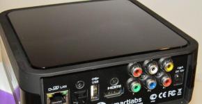
The manufacturer carefully included a control board with a reinforced power connector already soldered into the kit, since it’s definitely not worth driving almost 7 amperes through a regular 5.5mm plug:

After assembling the printer, I took up the heated bed:

Aluminum did not suffer from ideal evenness - I had to stick a skin on a glass table and polish it:

I protected the wires and the control board with a layer of heat-insulating foam and, for reliability, with a piece of touching pink culinary silicone mat, bought in Auchan for a hundred rubles. Please note that the manufacturer regularly offers to fix the desktop glass on the heated bed with paper clips - three pieces were carefully attached:

Here comes the problem:
Up to the prescribed 110 degrees, the heating accelerates for a long time. No, not like that: LONG. Forty minutes. Since the aluminum of the “hotbed” fits snugly to the carriers and perfectly transfers heat through them to the atmosphere, it first warms the entire structure with itself, and only then begins to slowly reach the desired degrees. Also, the heat is perfectly flowing to the sides and top.I struggled with the problem by covering the work surface with a silicone mat, but the solution turned out to be so-so. The heating has ceased to catch a cold from any draft, but the heating rate has not improved much. I began to look for a way to make a “fur coat” for a heated bed and prevent heat leakage.
Heat transfer from aluminum to glass was improved by a third of the KPT-8 tube.
In search of material for a “fur coat”, I found a non-standard solution: I took a cork sheet - a lining for a laminate, the trimmings of which were left over from the repair. Also, for the first time in 20 years, I had a chance to pick up a compass :)

As a result, the heated bed turned out to be dressed in a puff cake made of several sheets of cork, only glass sticking out. I drilled out the mounting holes so that the screws with a heat-insulating tube put on them would fit into them. I also insulated the washers from the heating plate with silicone rings to reduce heat transfer to the frame.

The result - the table warms up to 70 degrees in 5 minutes, in twenty it reaches the operating mode of 110 degrees.
And the result?
To test the printer, I took a well-known test model from Thingiverse:
Printed, default settings. Printer after automatic level adjustment:

Separate view of the sole of the model:

The layers, if you look closely, are visible, but if you consider that the product was not subjected to either “skinning” or “acetoning”, then the result came out worthy:

As a result, I am very pleased with the printer. Due to its design, it is quite difficult to calibrate it for printing models with a sole of more than 10 cm in diameter, but it allows you to print pieces up to 32 cm high. To print small models, it is enough to stick masking tape from the construction market on the glass - and the result is invariably excellent. The main thing is that now the child cannot be dragged away from the unit - he makes models and immediately prints them. It helps a lot that Thingiverse has a huge stock of models for installing Arduino sensors - and you can move from knee-high models with wires sticking out on the sides to more solid crafts.
I plan to buy +20 Add to favorites Liked the review +29 +51Hello people of the forum!
This article is not a 100% recipe for creating a hot desktop, but just an attempt to implement a spontaneous idea.
All owners of 3d printers are familiar with this textolite heating table, I also purchased it and was disappointed. It is impossible to get a temperature above 80 with its help. Whereas hardcore printing veterans recommend 110c when printing with ABS plastic.
Accordingly, a more powerful heating element was required. The search for a silicone heating element for 220v gave results of 1500-3800 rubles per copy. Given the fact that I spent 2000 rubles on the entire printer. this is unacceptable.

And that's how we got to the idea. Assemble the heating element yourself from improvised means, namely from nichrome and ceramics.
Calculation of the element at 350W.
I decided to limit the voltage with a rectifying diode, the voltage will be 110v at the peak and 55v at the conventional average. (please do not argue this idea).
Online calculator for calculating the length of nichrome wire http://forum220.ru/calc-nichrome-wire.php
Entering data
Thickness 0.8mm
Power 350W
Voltage 55v
We get the answer wire length 3.93m current 6.36A.
What you need, in fact, I selected the thickness of the wire so as not to wrap myself up to death. For example, if the voltage is not limited by a diode, then with a nichrome thickness of 0.8 mm, 62 m of wire will have to be distributed on the surface of 200 * 200 mm.
And so the distribution is 4m / 0.2 and that is 20 threads, that is, we lay the wire in 1 cm.

We are approaching the choice of a mixture for the base of the element, in general it should be ceramics, but forget about it, it is impossible to make it at home, so we go to build a store.
At first I chose glue for stoves and fireplaces, it did not dry well and was very fragile, and then I found out that it is also a heat-insulating material. (Who needs a bag of glue for the fireplace write in a personal)
Gypsum was next, it is also a good heat insulator, and even fragile. I decided to place the wire as close to the surface as possible. I tried to wind the winding on plaster stumps, but nothing happened.

So I bought a board and stuffed studs, this allowed me to pull the wire well close to the “heating” surface.

After that, it was filled with plaster without reaching the studs and reinforced the structure with 9 bamboo skewers.

After hardening, he transferred the structure to a mirror, crimped the copper wires, erected a “formwork” from cardboard and filled it with a large mass of gypsum. The whole week dried up, but not because I was patient, there was simply no time.


I bought a plug with a cord in the store, soldered the hot table relay, found a thicker diode in the bins, soldered it in series, cut a thermocouple 5 mm from nichrome into the gypsum body. It's time to turn it on.
I knew plaster was never dry. But I decided, “I’ll put 50so right now, or maybe 90so and everything will dry out in a day.” Installed, turned on. Dear children and everyone who should not touch the wires, this article discusses work with life-threatening voltage of 220v. Therefore, be sure to ensure that all connections are secure and adequately isolated.
Hellish hissing and screams of damned souls (who fried waffles will understand me) were heard from the printer, the stove arched, red threads of nichrome came out of her body, and the stove itself was covered with perspiration. I was stupid for about five seconds before I pulled out the socket of the hot table, and the relay was still closed, the thermocouple showed its 32co, and very slowly gained temperature.
So the results are unsatisfactory what's wrong:
The nameless diode gave a breakdown and died, as a result of which all 220v went to the table.
The thermocouple is too far from the nichrome filament and does not respond to heat. (gypsum thermal insulation)
Reworking:
Thermocouple in tight to the nichrome filament and fill with thermal paste.
We put the diode on 10A 600v.


Turn on.
The temperature jumped over 250c, the panel went into error.
The results are unsatisfactory, what is wrong:
The power of the table is excessive, design errors. The average voltage is 86v, not 55v as expected.
The temperature check in the firmware is set to 5000 milliseconds, which is a lot for our table, we set 500 milliseconds.
Checking the temperature of the table every half a second gave the results the table worked as it should, but with “kicks” by 15-18 degrees. This does not allow the firmware to adequately work out the heating of the table in the G code, that is, it waits until the temperature settles down indefinitely. I also put in a silicone mat for more even heat transfer to the glass.

That's what happened when installing 120co, I knew it could happen but not to me. As a result, you need a silicone mat for the entire surface and glass no larger than the heating element.

The problem of aligning this "brick" is still unresolved, but I think to solve it in the future.
This brick is not suitable for those whose printer drags the table along the X axis, it is very heavy.
And since the idea took place, you can even make it thinner.

In conclusion, don't be afraid to implement ideas while stumbling over contrived problems, analyze and solve problems as they come up and you will succeed.
I take this opportunity to say hello to my countrymen from Bestfilament and wish them good luck in all their endeavors.
Recently I decided to print on my printer a fairly large part, 10 cm long. It turned out that when printing 3-4 layers, the part begins to bend and peel off the table. No tricks helped. I didn’t want to make a heating table, but apparently there’s no getting around it .. Again, there was a problem - it’s impossible to buy a temperature sensor, you have to order it, but you’re too lazy to wait. Therefore, I decided to make a table without a temperature sensor, and it is not needed - you do not need to change the heating temperature, and therefore there is no need to measure it.
I looked at various types of similar tables and realized one pattern - most heating tables have a track width of about 5 mm. I decided to act at random, without calculations - maybe the temperature will be 100 degrees. According to my feelings and in comparison with existing models of heating tables, it should have been just that. I took a piece of one-sided textolite and sawed out a piece to fit the desktop of the printer 17x28 cm.
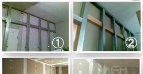
heating table blank
heat bed
marking of heating lines
I thought .. and decided to make them in the form of a snake (so that later I don’t have to worry about connecting adjacent tracks):
I took a sharp self-tapping screw and scratched the tracks along the drawn lines. I measured the resistance of the snake from beginning to end (i.e., the resistance of the entire table) - it was about 1.5 ohms. I measured the resistance of half the table - again 1.5 ohms. So it's short somewhere. No matter how much I fought, I never managed to get rid of the closures. Threw this thing with a self-tapping screw and dremel machined all the tracks. It turned out ugly, crooked, but without short circuits, resistance 2.2 Ohm. Here's what the table looks like:
heating table to the light.
no closures
Connected to a 12 V power supply directly - the temperature of the table is not more than 70 gr. At first I was upset that I would have to reduce the thickness of the tracks, but in time I attached this miracle to the printer table. It turned out that the print area of the printer is shorter than the desktop by as much as 10 cm!!! I quickly soldered the wires closer to each other and the temperature immediately jumped to 120 degrees. This is a victory The water immediately evaporates with a hiss.
I installed the table on the printer and realized that I need springs, it’s impossible to do without them - the temperature can dry out the wood (I have a wooden printer) and it’s much easier to adjust the horizontal position of the table with a spring-loaded table.
I made the springs from what I had - I wound the steel around the bolt, coil to coil:
Take it off and stretch it a little:
And we divide into parts:
They have a small power reserve, about 3-4 mm per 1.5 cm spring - this is quite enough. Here's the table I got:
It seems that they are completely compressed, but they are not, take my word for it
On the other side of the table, I made the springs shorter, they turned out to be softer, but the load in this part of the table is also less:
Here is the entire table:
heated table
Table temperature 105-110 gr. Glass from a photo frame from Ikea, the size turned out to be perfect. The thickness of the glass is 2 mm.
Noticed features - any textolite in the store is humpbacked, curved, etc. you definitely need glass to level the surface of the table. When heated, the textolite warped a little more. I don’t know how to make it perfectly flat .. but it doesn’t interfere, because. with the help of adjusting bolts and springs, the table is leveled in just a couple of minutes
Yes, I print on glass, smeared - cheap and cheerful. When, with difficulty, I could tear off the parts, one day a piece of Plexiglas came off instead of a part and I cut my finger deeply. Since then I have only printed on glass.
P.S. Some craftsmen print, alas .. nothing worked out for me with sugar - it crystallizes very quickly and there is no sense in it (higher temperatures are needed to melt it). Some print on the cryptic
I wrote about printing with ABS plastic on the cold table of the MC2 3D printer from Master Kit.
The technology works, but imposes some restrictions, primarily on the dimensions of the printed part in the horizontal plane. Having been experimenting with the MC2 printer with pleasure and refining it, I came to the conclusion that it would be time for me to get a heated table. There's more that the printer's electronics support this feature. And at the same time try to make this table adjustable by eliminating the AUTO_BED_LEVELING function. In principle, the function works well, I wrote about this in this article, but I wanted to try this option as well.
Actually, for this you only need to purchase the heater itself, the thermistor and springs for adjustment - this can be done on the website 3d.masterkit.ru. And figure out how to thermally untie the plastic parts of the printer, designed to mount the table, and the heater.
Rummaging in the cabinets, I found a piece of fiberglass. Good, smooth, 2mm thick. I sawed off a square 220x220mm from it. (The size of the heater is 214x214mm.) And, without thinking twice, I drilled 4 holes in it for M3x10 screws with a sunk head for fastening the textolite to standard glass holders and 4 holes for mounting the heater. I drilled holes of 2.5 mm in the details for fastening the glass and screwed the textolite with screws like self-tapping screws.
Now you need to attach the heater to the textolite through the springs. For a while I thought about how to make sure that the nuts of the adjusting screws were fixed, but then I decided to do without nuts at all. I cut the M3 thread directly in the fiberglass, it turned out somewhere around 4 turns. I tried several times to screw in and unscrew the spring-loaded screw. If you do this carefully, the thread holds well, does not deform. Let's see how the solution will behave during long-term operation; if the thread deteriorates, I will stick a metal nut-washer with an M3 thread on the textolite, you can print a retainer from ABS, or something like that.


Next, glue the thermistor into the central hole in the heater with heat-resistant tape or paper tape. It connects to the control board at connector T1. Also in the Marlin firmware, you must allow reading data from this sensor. To do this, in the Configuration.h tab, you need to change 0 to 1 in the line #define TEMP_SENSOR_BED 1
After that, in the RepetierHost program, you can see and set the table temperature value.
Glass for printing - how could it be without it - it is convenient to fix it with stationery paper clips. You can find them in any stationery department. This is how the sandwich turned out. Pretty hefty, I must say. I decided that it would be necessary to reduce in connection with this acceleration along the Y axis, and at the same time X. We climb into the firmware again. And we halve the following parameters in Configuration.h (new values are indicated):
#define DEFAULT_MAX_ACCELERATION(4500,4500,100,9000)
#define DEFAULT_ACCELERATION 1000
Probably, it will be a little slower to print, but okay, we are not in a hurry.


In order to exclude the influence of the extruder mounting on the positioning accuracy and to fully realize the possibility of adjusting the table, I decided to rigidly fix the extruder in its holder, for which I drilled through the details of its fastening and tightened it with screws. In this regard, I had to rearrange the Z-axis limit switch under the platform on which the X-axis is implemented. I printed a part with two slots for adjusting the limit switch and simply glued it with dichloroethane to the base connecting the three stepper motors from the bottom of the printer. Just in case, I also tightened it with a screw. Now the limit switch is triggered when the platform is lowered to the desired level.

As a power supply, taking into account the current consumption increased by 10A (!) I used an ownerless power supply from an old computer with a power of 350W. It gives 15A current on the 12V yellow wire. The heater is connected to the terminals D8 of the control board. I checked the voltage at full load, it stays at the level of 11.5-11.6V. The block does not heat up. Good!
Now let's try to print something with ABS. Test cube 30x30mm, for example. We see in RepetierHost: 100 degrees on the table, 250 on the extruder. 200 µm layer, blowing off.

It stinks a little, but with the window open it is quite tolerable. For me, let it smell like that, even nice!


It turned out quite a decent cube, agree! By the way, when printing, the part was not blown, because it cools the extruder by 10 degrees.


I was satisfied with the print quality, but after a while I realized that with my experiments I blocked access to the control board! Adjust the driver current or switch what ... that's an ambush. It turned out that if you loosen the fasteners and carefully remove the polished shafts along which the table moves, then it can be removed in a wonderful way and opens access to the board. At the same time, all settings of the table with springs are completely preserved. Phew!
So I have not yet decided which calibration I like best, auto-leveling or springs on the table ...
Happy printing everyone!