Memory reversible turns counter - Ready-made devices - Article catalog - Microcontrollers - it's easy! Instructions for making a winding machine Counter from a calculator for winding coils.
And I didn’t think about anything until some simple counting device caught my eye. There was no doubt that it should be adapted for counting the number of turns of wire wound onto transformer coils, because there is no higher pleasure than thinking about something else while doing one thing. Is it possible that being in a state of complete concentration (akin to trance) and at the same time the tambourine is counting the turns, is this possible? And it’s not difficult to adapt. As well as finding the same thing or something similar. There are a lot of different meters now, and even a faulty one will do. Moreover, at the beginning you need to carefully “gut” it, remembering the relative positions of the parts (or better yet, photograph it all), and throw out everything unnecessary.
So, from the internal contents we leave the digital wheels, gears, axles for their mounting and axle holders, which we assemble “in place” (the way they stood before disassembly). It is advisable to glue the axles into the left rack. On digital wheels, next to the central hole there is another one - an assembly one, with which the wheel is put on a pin (a smooth and elastic wire that is removed before installing the cap). Without this assistant nothing will work. At the same time, before attaching the second rack, do not forget to put a rubber belt (preferably flat) of a suitable length on the drive wheel.

In the bottom part and in the cap, in the center, we make through holes (for example, 3 mm in diameter) for further fastening them with a screw and nut. This is necessary, because during operation there will be vibrations of the structure, during which everything we have assembled will constantly fall apart (checked). Also, a cut is made in the cap with a width slightly less (so that the belt does not fly off) of the driving digital wheel and a length across the entire cap. One more thing will not be superfluous - two holes in the side wall of the cap; they will be useful when installing it in place, because in this case you need to get the upper slots on the racks into the corresponding grooves (by the way, the left and right ones are different sizes - do not confuse them) inside the cap. Use a screwdriver to guide it through them. In the bottom part, you need to provide a couple of holes for attaching the entire already assembled structure to the winding device with screws or screws.

How and where to attach the assembled meter to the winding device - complete freedom of creativity. But their working connection is like this:

A pulley (this is ideal) or a bushing made of soft plastic with an internal diameter of slightly less than 6 mm (to fit under tension) and an external diameter at which one turn of the drive shaft will correspond to one turn of the counter’s driving digital wheel is installed on the drive shaft of the winding device. The simplest option is to wrap narrow adhesive tape of sufficient thickness (let’s say up to a diameter of 20 mm) on a suitable polyvinyl chloride or thick plastic tube 10 mm long (say, electrical tape, but worse) and begin setting up, if necessary, unwinding or rewinding the tape to the optimal thickness.

In short, we achieve the ratio of the gear ratio One to one. Without particularly persisting, I managed to make an error of +1 turn per 150 revolutions of the winding device shaft. Well, a known error completely excludes an unsatisfactory result of the work. Now, while working, you can dream, sing songs and, if necessary, adequately repel the attacks of other family members. With wishes of success, Babay.
Discuss the article TURN COUNTER
In the last article I shared with you, . The thick wire was wound manually, since it was not possible to carefully lay the coil to the coil in any other way at home. With a smaller diameter of the winding wire, a more technologically advanced method can be used, which will reduce the time and effort during winding, and also, which is important, the manufacture of the transformer will not differ from the factory version. Next, we will describe the simple design of a homemade winding machine, with which you can easily wind coils, chokes, power and sound transformers.
The base (bed) of the winding machine
You can make a machine for winding transformers from any durable, easily processed material. The most suitable would be: metal, plywood (wood) or plastic. Depending on what you have available and what you like to work with most, you can give preference to one material or another.
I mostly make homemade things from what I have on hand, and in this case, in the rubble of junk called “useful around the house” I found scraps of 10 mm semi-rigid plastic, which I successfully used in the design of the winder and its elements.
Initially, during development, it is necessary to make a test layout, think through the layout of the winder, and ask yourself what necessary functions the device should perform. During the prototyping process, it is easy to add and improve, adjust the dimensions, which will allow you to get the most successful option at the end.
According to the project, we have three axes:
The first axis (winder) - the winding coil of the transformer will rotate on it. At one end there will be a counter for the number of turns made, and at the other end there will be an axle rotation drive with a set of pulleys. The drive can be manual in the form of a handle attached to an axis or electric in the form of a stepper motor.
The second axis (stacker) - the lead of the wire stacker will “run” on it, and the second set of pulleys will be attached to the axis, which will be interfaced with the first set of pulleys on the first axis through a belt drive using a belt.
The third axis (reel holder) serves as a support for the reel with winding wire.
At the design stage, it is necessary to correctly space the axes between each other so that the frame of the winding transformer coil does not cling to the machine and does not touch another axis, and also select the height of the wire coil so that you can freely hang coils of different sizes. An additional axis can be provided for winding and winding wire from reel to reel.
According to the markings on the selected material for the bed, using a hacksaw for metal, we cut out parts of the base of the machine (sides, bottom, cross members), and also drill the necessary holes. Using metal corners and self-tapping screws, we fasten all the components together.


Revolution counter for counting turns
One revolution is equal to one turn - this is how I used to calculate in my head when winding a transformer on a primitive device. With the advent of a full-fledged winding machine with a counter provided, it became much easier, but the most important thing is that when winding turns, the error rate was reduced to almost zero.

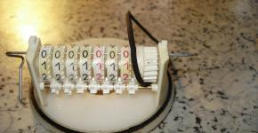
The winder under consideration uses a mechanical counter UGN-1 (SO-35) from Soviet equipment. It can be replaced with a bicycle meter or a mechanical counter from an old household tape recorder, where it measured tape consumption. You can also assemble a simple meter with your own hands, having only a calculator, a reed switch, two wires and a magnet.
Disassemble the calculator into two contacts closed by the “equal” button, solder two wires, and solder a reed switch to the ends of the wires. If you bring a magnet to the reed switch, its plates inside the glass flask will close and the calculator will simulate pressing a button. Using the 1+1 addition function of the calculator, you can count the revolutions.


Next, we attach the homemade disk to the first axis. We glue a magnet to the disk, and attach a reed switch to the machine body or bracket. We position the reed switch so that when the disk rotates, the magnet passes next to the reed switch and closes its contacts.
Using this principle, you can replace the reed switch with a limit switch, and make the disk in the form of an eccentric. The eccentric disk, rotating with its convex part, will press on the limit switch
Coil stacker
The wire layer is used for uniform winding, turn to turn, of the winding wire onto the frame of the transformer or coil being manufactured. The winding density depends on the speed at which the axes rotate, as well as on the diameter of the selected wire. The required ratio of rotation speed of the first and second axles can be achieved using pulleys and a belt drive. When the machine's well-functioning mechanism is operating, the stacker roller simultaneously moves with a certain pitch and the wire is laid on the frame of the winding transformer. It cannot be explained in a nutshell, but upon further reading of the article everything will become clear.
The design in question uses a factory-made M6 rod stud with a thread pitch of 1 mm. Bearings are fixed parallel to each other into the sidewalls of the winding machine bed into pre-drilled holes for them, then a pin is inserted into them. For best sliding, lubricate the bearings. A guide roller moves on the pin, through which the wire is threaded.


You can make a guide roller for laying wire yourself, having a small piece of U-shaped aluminum profile, an elongated bushing nut that matches the thread of the stud, and a feed roller with a groove in the middle.

Holes parallel to each other are drilled in the U-shaped profile. The top pair of holes is for the roller, and the bottom pair is for the extended nut. The diameter of the upper holes in the profile walls is selected along the axis on which the roller will be fixed, and the lower ones are a millimeter larger than the diameter of the stud thread. An elongated nut is tightly adjusted to fit the distance between the profile walls. This structure is then screwed onto the paver stud.


The stud is secured with nuts on the sides so that it can rotate without displacement. A spare pin is left on one side so that pulleys can be screwed onto it to mate the first and second axles.
Two pulleys are connected by a belt drive
The axles in the winding machine are connected to each other by a system of pulleys of different radii. The pulleys attached to the axles rotate using a belt drive. A belt is used as a belt.
— The stacker axis pulley is 100mm;
— The pulley on the axis with the attached coil (winder) is equal to the thickness of the required wire, multiplied by 100.
For example, for 0.1 mm wire, we use a 10 mm pulley on the axis of the winder. For a diameter of 0.25 wire, a 25 mm pulley.
If possible, it is better to make pulleys with a pitch of 1 mm and select them during the winding process using this formula
The error depends on the accuracy of the diameter of the manufactured pulleys and the tension of the belt. If you use a stepper motor with a gear transmission as a drive in the design instead of a belt and precisely cut pulleys, then the error can be brought closer to zero.
Now I’ll tell you how to make a pulley with your own hands at home without turning to a turner. My set of pulleys is made of the same material as the bed of the winding machine. Using a compass, I marked out the required diameters of the pulleys and added a few millimeters on the larger side to machine the groove for the belt to the required size. Holes were drilled along the contour of the markings with a screwdriver and partitions were cut between them. So I collected the required number of blanks for the pulleys. I used an unnecessary “Assistant” meat grinder as a lathe.


I don’t remember exactly, I cut a thread on the meat grinder motor shaft, or it turned out to be suitable, but a pin was screwed through a long bushing nut. A blank with a slightly larger diameter than the required pulley was screwed onto the stud through nuts and washers. The meat grinder was turned on and all the irregularities were rounded to a round shape with a metal hacksaw/file, and a groove (groove) for the belt was machined with a needle file. During the process, the diameters of the homemade pulleys were periodically checked with calipers.


Components of a winding machine and its operating principle
The elements of the winding machine were assembled slowly. Almost everything was taken from old Soviet film equipment. Moving parts: handle, axle studs, guide roller - everything is equipped with bearings. Studs, nuts, washers and angles were purchased at a hardware store. I only had to spend money on studs, long nuts and angles. Otherwise, everything is made from available materials.

To accurately select the wire winding density, a set of several pulleys is threaded onto the stacker pin. So, in the case of loose winding, it was possible to move the belt one size and adjust the speed of rotation of the axes. During the process of winding the wire, the belt is twisted depending on the direction of the winding stroke according to the figure-of-eight shape or the direct position of the belt. You should make a couple of dozen test turns to correctly adjust the pulleys to the diameter of the wire.


A base is made from wood or other material in the shape of the inside of the transformer coil and fixed to the stud with wing nuts. You can also make universal holding corners to secure the coil. A demonstration of the operation of the winding machine is shown in the video:
[Here will be a video of the transformer winding process]


![]()
About the author:
Greetings, dear readers! My name is Max. I am convinced that almost everything can be done at home with your own hands, I am sure that everyone can do it! In my free time I like to tinker and create something new for myself and my loved ones. You will learn about this and much more in my articles!
For all radio amateurs or enthusiasts interested in sound-reproducing equipment, a winding machine is an extremely popular piece of equipment. Such devices are used for winding single-layer and multi-layer cylindrical coils for transformers.
In this article we will study the design and operating principle of a winding machine, and also consider step-by-step instructions, following which you can make such equipment with your own hands.
1 Design and principle of operation
The winding machine is indispensable in the production of similar products. There are two types of such units - automatic and manual, while the latter are practically not common in the industrial sector due to limited functionality.
However, the overall dimensions, heavy weight and cost of automatic winders make them inapplicable in everyday life, so it is better to get a manual machine for your home. The standard design of such a device consists of the following elements:
- a supporting frame made of two vertical posts made of metal or wood, between which horizontal axes are fixed (on the central post - for the plates with a wheel, on the outer one - for the coil itself);
- large and small gears that transmit torque to the reel;
- a handle fixed on a large gear, through which the axis with the reel rotates;
- fastening elements - screws and nuts.
![]()
The principle of operation of such a device is extremely simple - rotating the handle leads to winding a wire or cable onto a rotating frame; the stacker guide, which moves the wire in a horizontal plane, is responsible for the uniformity of winding.
Monitoring the number of turns can be done both visually and using special counters, the simplest of which is a regular bicycle odometer. In more advanced machines, a special magnetic reed sensor is used as a counter.
1.1 Magazine machines
Among industrial winding units, the cable winding machine SRN-05M3 is widely popular. This model was put into operation during the Soviet era, and since then has proven itself well due to its high reliability and performance. On the secondary market, SRN-05M3 can be found for 15-20 thousand rubles.

SRN-05M3 is made of cast iron, the weight of the equipment is 80 kg, the dimensions are 877 * 840 * 142 cm. The machine allows you to wind single-layer, double-layer and toroidal coils in automatic laying mode. The minimum cable diameter is 0.05 mm, the maximum is 0.5 mm. The unit is equipped with a single-phase electric motor of the UL-62 type, the power of which is 0.18 kW. The highest rotation speed during winding is 5100 rpm.

For household use, the best choice would be a manual machine NZ-1 (China). Despite the country of origin, the NZ-1 is quite reliable and functional equipment. The unit is designed for winding coils with a diameter of up to 150 mm, with a maximum width of no more than 100 mm. The gear ratio is 1:08 in fast winding mode and 1:0.1 in slow winding mode. Maximum speed - no more than 1000 rpm.
NZ-1 is equipped with a mechanical type thread counter. The body is made of metal, the supporting frame is made of cast iron. The machine is equipped with a pulley, which allows you to connect an electric motor to it via a belt drive and operate in automatic mode. The cost of such equipment varies between 4-5 thousand rubles.
1.2 Homemade winding machine (video)
2 Making a winding machine with your own hands
The cable winding machine presented in this section of the article allows you to work with coils on a square, round and rectangular frame with a diagonal of up to 200 mm; it can be equipped with different pulleys, which will allow you to change the winding pitch within 0.3-3.2 mm.

The diagram below shows the frame of the machine. To assemble the frame, metal sheets with a thickness of 15 mm (for the base) and 5 mm (for the side sections) are used. Saving on metal thickness is not welcome, as it leads to a decrease in the weight of the unit and, as a result, a deterioration in its stability.
You will need to cut out the frame blanks (the dimensions are respected) and drill two through holes in them, then the sides are welded to the base plate. You need to mount 2 bearings in the lower hole, and bushings for the rotation shaft in the upper hole.

As a shaft, you can use a 12 mm smooth reinforcement bar, which must first be sanded and painted. For the stacker sleeve, you can take a rod with a diameter of 10 mm, along the entire length of which a thread of standard M12 * 1.0 is cut.

It is better to make triple pulleys, but keep in mind that their total thickness should not exceed 20 mm. With greater thickness, it will be necessary to additionally increase the length of the shafts by a similar size. The combination of pulleys indicated in the diagram allows the use of 54 different winding steps. If you need to work with wires with a diameter of less than 0.31 mm, you will need an additional 12/16/20 mm pulley, with which you can wind 0.15 mm wires.

To construct a manual drive, you will need a large gear and handle, which are fixed by means of a collet clamp on the upper shaft. Thanks to the use of a collet, you can, if necessary, interrupt the winding by fixing the handle, thereby preventing the reel from unwinding.
The thread counter for the winding machine is made from a regular calculator. You will also need a magnet with a reed sensor (can be bought at any radio equipment store), the leads of which must be connected to the contacts of the calculator on the “=” button.
2.1 How to work on a homemade machine?
So, the equipment is ready, how to work on it? To install the winding frame, it is necessary to extend the upper shaft from the mounting socket to a length equal to the length of the frame. Next, the right disk and the coil mandrel are mounted on the shaft, on top of which the coil itself is put on. The next step is to install the left disk and screw on the nut, after which everything is installed in its original position.

A nail is placed in the hole on the upper shaft and the frame is centered, after which the frame is clamped with a nut. Further operations are performed in the following sequence:
- A pulley of suitable diameter is placed on the feed shaft.
- By rotating the pulley, the stacker moves to the extreme position, to one of the sides of the reel.
- A wire belt is put on the pulley - in a ring or figure eight. The end of the wire must be threaded under the middle shaft, placed in the stacker chute and secured to the frame. The wire tension is adjusted using clamps on the handler.
- At the beginning of winding, the combination “1+1” is typed on the calculator, after which the handle is rotated. With each full revolution of the shaft, the calculator will independently increase the number on the screen by one, thereby counting the number of turns of the wire.
Since this equipment has an extremely simple device that does not have any kind of winding machine control controller, during operation you will need to constantly monitor the reel and, if necessary, adjust the cable on the frame manually.

If you want to make the machine more functional, you will need to complicate the design by adding a controller to it. This will allow you to automate the workflow, however, for fully mechanical pairing, you need to install a stepper motor in the controller (a regular 24-volt drive operating in 44-60 steps per revolution mode will do). Power transistors for this kit are selected based on the characteristics of the motor. The ATmega8 device is ideal as a controller; you can buy it for 150-200 rubles.
The site is in test mode. We apologize for any interruptions or inaccuracies.
We ask you to write to us about inaccuracies and problems using the feedback form.
Electronic thread counter for winding machine.
Among the simplest and yet very necessary technological devices, which even inexperienced radio amateurs can make independently, is a manual winding machine. This is a steel shaft with M6 thread, rotating in two racks; At one end there is a handle for rotation. The posts are screwed to a massive base. In order not to count the number of shaft revolutions—the number of turns of the winding—the machine is usually equipped with a mechanical counter. However, a convenient miniature revolution counter with the ability to reset the readings was and remains in short supply. An alternative to a mechanical counter is the electronic one described in this article. The proposed reversible electronic counter is assembled on nine CMOS microcircuits (K561TL1, 4 x K561IE14, 4 x K176ID2), a KT315B transistor and a four-digit LCD indicator IZHTs5-4/8. The rotation pulse sensor is made on the basis of two reed switches, which close when a permanent magnet passes near them, mounted on a leash mounted on the machine shaft. The device counts the number of shaft revolutions from 0 to 9999. Drawings of printed circuit boards are given, on one of which an LCD indicator is mounted, and on the other - all other parts of the counter.
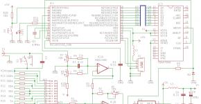
Option 1: ATmega8 + Nokia 5110 LCD + 3V power supply
The circuit uses Atmega8-8PU (external quartz with a frequency of 8MHz), Nokia 5110 LCD and a transistor for processing pulses from a reed switch. The 3.3V voltage regulator provides power to the entire circuit.
All components were mounted on the breadboard, including connectors for: ISP programmer (USBAsp), 5110 Nokia LCD, power (5V supplied to 3.3V regulator), reed switch, reset button and a 2-pin connector used to read winding polarity machine drive motor to know whether to increase or decrease the counter.
Purpose of connectors:
J1: Power. 5V is supplied to the connector and then to the L7833 stabilizer to obtain the 3.3V voltage used by ATmega8 and LCD.
J2: LCD connector for Nokia 5110 LCD.
J3: Reed switch. Pulse input for counting by microcontroller.
J4: Polarity connector. It must be connected in parallel with the motor winding. The tracking circuit was designed for a 12-volt motor, but it can be applied to other motor voltages by adjusting the values of the voltage dividers formed by R3-R4 and R5-R6. If the motor is connected to straight polarity, PD0 will have a high log. level, if the motor is connected to reverse polarity, then PD1 will have a high log. level. This information is used in the code to increment or decrement the counter.
J5: Counter reset. When you press the button, the counter will be reset.
ISP Connector: This is a 10-pin connector for the USBAsp AVR programmer.
Device diagram
Photo of the finished device


Option 2: ATmega8 + 2x16 HD44780 LCD + 5V power supply
Some of my readers have asked for a version of the counter that uses a 2x16 HD44780 display (or a smaller 1x16 variant). These displays require a 5V supply voltage, so a 3.3V stabilizer is not relevant.
Device diagram


Microcontroller configuration bits for both options: LOW - 0xFF, HIGH - 0xC9.
| Archive for the article "Coil counter for winding machine" | |
| Description:
Source code (C), firmware files for the microcontroller |
|
| File size: 111.35 KB Number of downloads: 257 |