Switching current stabilizer for powering high-power LEDs. Current stabilizer for two output LEDs
In discussions of electrical circuits, the terms "voltage regulator" and "current regulator" are often used. But what is the difference between them? How do these stabilizers work? Which circuit needs an expensive voltage regulator, and where is a simple regulator enough? You will find answers to these questions in this article.
Consider a voltage regulator using the LM7805 device as an example. Its characteristics indicate: 5V 1.5A. This means it stabilizes the voltage and it is up to 5V. 1.5A is the maximum current that the stabilizer can conduct. Peak current. That is, it can give away 3 milliamps, and 0.5 amperes, and 1 ampere. As much as the current required by the load. But no more than one and a half. This is the main difference between a voltage stabilizer and a current stabilizer.
Types of voltage stabilizers
There are only 2 main types of voltage stabilizers:
- linear
- impulse
Linear Voltage Regulators
For example, microchips BANK or , LM1117, LM350.
By the way, KREN is not an abbreviation, as many people think. This is an abbreviation. The Soviet stabilizer chip, similar to the LM7805, had the designation KR142EN5A. Well, there is also KR1157EN12V, KR1157EN502, KR1157EN24A and a bunch of others. For brevity, the entire family of microcircuits began to be called "KREN". KR142EN5A then turns into KREN142.
Soviet stabilizer KR142EN5A. Analog LM7805.

Stabilizer LM7805
The most common type. Their disadvantage is that they cannot operate at a voltage lower than the declared output voltage. If it stabilizes the voltage at 5 volts, then it needs to be applied to the input at least one and a half volts more. If you apply less than 6.5 V, then the output voltage will “sag”, and we will no longer get 5 V. Another disadvantage of linear stabilizers is strong heating under load. Actually, this is the principle of their work - everything that is higher than the stabilized voltage simply turns into heat. If we apply 12 V to the input, then 7 will be spent on heating the case, and 5 will go to the consumer. At the same time, the case will heat up so much that without a radiator, the microcircuit will simply burn out. Another serious drawback follows from all this - a linear stabilizer should not be used in battery-powered devices. The energy of the batteries will be spent on heating the stabilizer. All these shortcomings are deprived of impulse stabilizers.
Switching voltage stabilizers
Switching stabilizers- devoid of the disadvantages of linear, but also more expensive. This is no longer just a microcircuit with three pins. They look like a board with parts.

One of the options for the execution of a pulse stabilizer.
Switching stabilizers There are three types: lowering, increasing and omnivorous. The most interesting are omnivores. Regardless of the input voltage, the output will be exactly what we need. The omnivorous impulsnik does not care that the voltage at the input is lower or higher than the desired one. He automatically switches to the mode of increasing or decreasing the voltage and keeps the specified output. If the characteristics state that the stabilizer can be input from 1 to 15 volts and the output will be stable 5, then it will be so. In addition, heating switching regulators is so small that in most cases it can be neglected. If your circuit will be powered by batteries or placed in a closed case, where strong heating of the linear stabilizer is unacceptable - put a pulse. I use penny adjustable switching voltage regulators that I order from Aliexpress. You can buy.
Fine. And what about the current stabilizer?
I won't discover America if I say that current stabilizer stabilizes current.
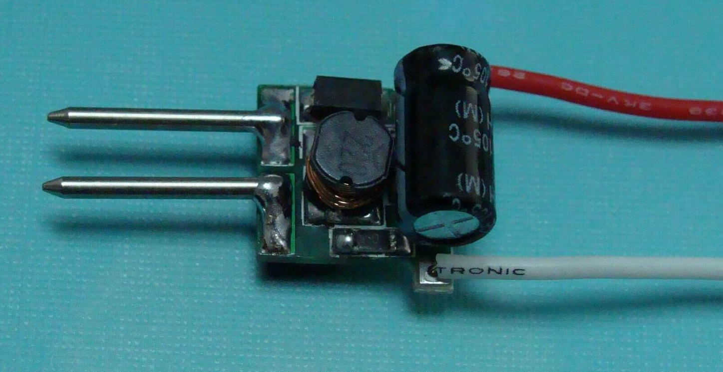
Current regulators are sometimes also referred to as LED drivers. Outwardly, they look like switching voltage stabilizers. Although the stabilizer itself is a small microcircuit, everything else is needed to ensure the correct mode of operation. But usually the whole circuit is called a driver at once.

This is what a voltage stabilizer looks like. The circuit circled in red is the same circuit that is the stabilizer. Everything else on the board is binding.
So. The driver sets the current. Stable! If it is written that the output will have a current of 350mA, then it will be exactly 350mA. But the output voltage can vary depending on the voltage required by the consumer. Let's not get into the wilds of the theory about that. how it all works. Just remember that you do not regulate the voltage, the driver will do everything for you based on the consumer.
So why is all this necessary?
Now you know how a voltage stabilizer differs from a current stabilizer and you can navigate their diversity. Perhaps you never understood why these things are needed.
Example: you want to power 3 LEDs from the car's electrical system. As you can learn from, it is important for the LED to control the current strength. We use the most common option for connecting LEDs: 3 LEDs and a resistor are connected in series. Supply voltage - 12 volts.
With a resistor, we limit the current to the LEDs so that they do not burn out. Let the voltage drop across the LED be 3.4 volts.
After the first LED, 12-3.4 = 8.6 volts remains.
We have enough for now.
On the second, another 3.4 volts will be lost, that is, 8.6-3.4 \u003d 5.2 volts will remain.
And for the third LED is also enough.
And after the third, 5.2-3.4 \u003d 1.8 volts will remain.
If you want to add a fourth LED - it's not enough.
If the supply voltage is raised to 15V, then enough is enough. But then the resistor will also need to be recalculated. A resistor is the simplest current stabilizer (limiter). They are often placed on the same tapes and modules. It has a minus - the lower the voltage, the lower the current on the LED will be (Ohm's law, you can't argue with it). This means that if the input voltage is unstable (usually it is in cars), then you first need to stabilize the voltage, and then you can limit the current with a resistor to the required values. If we use a resistor as a current limiter where the voltage is not stable, we need to stabilize the voltage.
It is worth remembering that it makes sense to put resistors only up to a certain current strength. After a certain threshold, the resistors start to get very hot and you have to install more powerful resistors (why is the resistor talking about power in this device). Heat dissipation increases, efficiency decreases.
Also called LED driver. Often, those who are not very versed in this, the voltage regulator is simply called the LED driver, and the switching current regulator - good LED driver. It delivers stable voltage and current at once. And almost never heats up. This is how it looks like:
Every time I read new blog entries, I encounter the same error - put current stabilizer where needed Voltage regulator and vice versa. I will try to explain on my fingers, without delving into the jungle of terms and formulas. It will be especially useful for those who put driver for powerful LEDs and nourishes many of the weak with it. For you - a separate paragraph at the end of the article.
Let's start with the concepts:
VOLTAGE REGULATOR
Based on the name - stabilizes the voltage. If it is written that the stabilizer is 12V and 3A, then it stabilizes precisely for a voltage of 12V! But 3A is the maximum current that the stabilizer can give. Maximum! And not "always gives 3 amps." That is, it can give out 3 milliamps, and 1 ampere, and two ... How much your circuit eats, it gives so much. But no more than three. Actually this is the main thing.


Once they were like that and connected TVs to them ...
And now I will move on to describing the types of voltage stabilizers:
Linear stabilizers (the same ROLL or LM7805/LM7809/LM7812 etc.)
Here it is - LM7812. Our Soviet analogue - KREN8B
The most common type. They cannot operate at a voltage lower than that indicated on his belly. That is, if the LM7812 stabilizes the voltage at 12 volts, then it needs to be applied to the input by at least about one and a half volts more. If it is less, it means that the output of the stabilizer will be less than 12 volts. He cannot take the missing volts out of nowhere. That's why it's a bad idea - to stabilize the voltage in the car with 12-volt rolls. As soon as the input is less than 13.5 volts, it starts to give less than 12 at the output.
Another disadvantage of linear stabilizers- strong heating at such a good load. That is, in a village language - everything that is above the same 12 volts turns into heat. And the higher the input voltage, the more heat. Up to the temperature of frying eggs. We loaded it a little more than a couple of small LEDs and that's it - we got an excellent iron.
Switching stabilizers - much cooler, but also more expensive. Usually, for an ordinary buyer, this already looks like a kind of scarf with details.
For example, here is such a handkerchief - a switching voltage stabilizer.
There are three types: lowering, increasing and omnivores. The coolest are omnivores. They do not care that the input voltage is lower or higher than desired. He automatically switches to the mode of increasing or decreasing the voltage and keeps the specified output. And if it is written that it can be input from 1 to 30 volts and the output will be stable 12, then it will be so.
But more expensive. But tougher. But more expensive...
If you don’t want an iron from a linear stabilizer and a huge cooling radiator to boot, put a pulse one.
What is the conclusion on voltage stabilizers?
SET HARD VOLTS - and the current can swim as you like(within limits of course)
CURRENT STABILIZER
When applied to LEDs, they are also called "LED driver". Which would also be true.
Here, for example, is a ready-made driver. Although the driver itself is a small black eight-legged microcircuit, the whole circuit is usually called the driver at once.
Sets the current. Stable! If it is written that the output is 350mA, then even if you crack, it will be so. But the volts at its output can vary depending on the voltage required by the LEDs. That is, you do not regulate them, the driver will do everything for you based on the number of LEDs.
If it is very simple, then I can only describe it this way. =)
What about the conclusion?
SET A HARD CURRENT - and the voltage can float.
Now - to the LEDs. After all, all the fuss is because of them.
The LED is powered by CURRENT. It does not have a VOLTAGE parameter. There is a parameter - voltage drop! That is how much is lost. If it is written on the LED 20mA 3.4V, then this means that it needs no more than 20 milliamps. And at the same time, 3.4 volts will be lost on it. Not for power, you need 3.4 volts, but simply “lost” on it!
That is, you can power it at least from 1000 volts, only if you give it no more than 20mA. It will not burn out, will not overheat and will shine as it should, but after it there will be 3.4 volts less. That's all science. Limit the current to him - and he will be full and will shine happily ever after.
Here we take the most common option for connecting LEDs(this is used in almost all tapes) - 3 LEDs and a resistor are connected in series. We feed from 12 volts. We limit the current to the LEDs with a resistor so that they do not burn out (I don’t write about the calculation, there are a lot of calculators on the Internet). After the first LED, 12-3.4= 8.6 volts remains……… We still have enough. On the second, another 3.4 volts will be lost, that is, 8.6-3.4 \u003d 5.2 volts will remain. And for the third LED is also enough. And after the third, 5.2-3.4 \u003d 1.8 volts will remain. And if you want to put the fourth, then it's not enough. Now, if you power not from 12V but from 15, then that's enough. But we must take into account that the resistor will also need to be recalculated. Well, actually, they came smoothly to ...
The simplest current limiter is a resistor.
They are often placed on the same tapes and modules. But there are downsides - the lower the voltage, the lower the current on the LED. And vice versa. Therefore, if the voltage jumps in your network, that horses jump through barriers at show jumping competitions (and in cars this is usually the case), then we first stabilize the voltage, and then limit the current to the same 20mA with a resistor. And that's it. We don’t care about power surges anymore (the voltage stabilizer works), and the LED is full and shines to the delight of everyone.
That is - if we put a resistor in the car, then you need to stabilize the voltage.
You may not stabilize if you calculate the resistor for the maximum possible voltage in the car network, you have a normal on-board network (and not a Chinese-Russian tazoprom) and make a current margin of at least 10%.
Well, besides, resistors can only be set up to a certain current value. After a certain threshold, the resistors start to heat up like hell and you have to greatly increase them in size (resistors 5W, 10W, 20W, etc.). We smoothly turn into a large iron.
There is another option- put something like LM317 in the current stabilizer mode as a limiter.
LM317. Externally, like the LM7812. The body is one, the meaning is somewhat different. But they also heat up, because this is also a linear regulator (remember I wrote about ROLL in the paragraph about voltage stabilizers?). And then they created...
Switching current stabilizer (or driver).
That's exactly what I'm talking about. In the picture we are talking about 1W LEDs, but the picture is the same with any other.
This is exactly what we see in Chinese modules and corn, which burn like matches after a week / month of work. Because LEDs have a hell of a spread, and the Chinese save more on drivers than anyone else. Why don't branded modules and lamps of Osram, Philips, etc. light up? Because they make a rather powerful rejection of LEDs and 10-15% of the wildest number of LEDs produced remains, which are almost identical in parameters and you can make such a simple look from them, which many are trying to do - one powerful driver and many identical chains of LEDs without drivers. But only in the conditions “I bought LEDs on the market and soldered it myself”, as a rule, it will not be good for them. Because even the “non-Chinese” will have a scatter. It may be lucky and work for a long time, or it may not.
Remember once and for all! I am begging you! =)
And it's easy - to do it right and to do "look how I saved, and the rest are fools" - these are somewhat different things. Even very different. Learn to do not like the notorious Chinese, learn to do it beautifully and correctly. This was said a long time ago and not by me. I just tried to explain the common truths for the hundredth and five hundredth time. Sorry if I didn't explain well =)
Here's a great illustration. Do you think I didn’t want to save money and reduce the number of drivers by 3-4 times? But this is correct, which means it will work happily ever after.
And finally, for those to whom even such a presentation was too abstruse.
Remember the following and try to follow it (here a "string" is a single LED or multiple LEDs in SERIES):
1.—- EVERY chain has its own current limiter (resistor or driver ...)
2. - Low-power circuit up to 300mA? We put a resistor and that's enough.
3. Is the voltage unstable? We put the VOLTAGE STABILIZER
4. - Is the current more than 300mA? We put on EVERY chain a DRIVER (current stabilizer) without a voltage stabilizer.
This is how it will be right and most importantly - it will work for a long time and shine brightly! Well, I hope that all of the above will save many from mistakes and help save money and nerves.
A wide variety of electronics on the market today contributes to the formation of high requirements for power supply. There are a huge number of ready-made modules and electronic components. For LEDs, special stabilizers are often used. This technology is used in almost every modern LED spotlight, lamp or lamp.
Among users who want to make a current stabilizer for LEDs with their own hands, the LM317 chip (including its analogues), which belongs to a subclass of linear stabilizers, is the most popular.
Such devices are divided into several types:
- Linear current regulator for LEDs, the input voltage of which does not exceed 40 V at a current of 10 A.
- Pulse devices that have a low input voltage (for example, a pulse PWM controller);
- Switching current stabilizer, which is characterized by a high input voltage.
The choice of the most suitable stabilizer depends on the efficiency and cooling system of the device.
Step-up and step-down stabilizers
A step-up regulator converts a low input voltage to a higher output voltage. This option is used for LEDs with a low-voltage power supply (for example, in a car, it may be necessary to increase 12 volts for LEDs to 19V or 45V). Step-down regulators, on the contrary, reduce the high voltage to the desired level. All modules are divided into universal and specialized. Universal ones are usually equipped with two variable resistances - to obtain the desired parameters of current and voltage at the output. For specialized devices, the output values \u200b\u200bare most often fixed.
As a stabilizer for LEDs, a special current stabilizer is used, the circuits of which can be found in large numbers on the Internet. The popular model here is Lm2596. LEDs are often connected to the car's mains or battery through a resistor. In this case, the voltage can fluctuate in pulses up to 30 volts, due to which low-quality LEDs can fail (flashing navigation lights with partially inoperative LEDs). Current stabilization in this case can be carried out using a miniature converter.

Simple current converter
Assembling a miniature current converter with your own hands is considered quite simple. Such voltage stabilizers are usually made in the current stabilization mode. In this case, one should not confuse the maximum voltage for the entire unit and the maximum load on the PWM controller. A system of low-voltage capacitors for 20 V can be installed on the unit, and a pulse microcircuit can have an input of up to 35 V. The simplest do-it-yourself LED current stabilizer is the LM317 variant. You only need to calculate the resistor for the LED using an online calculator.
For the LM317, you can use a handy power supply (for example, a 19 V power supply from a laptop, a 24 V or 32 V power supply from a printer, or a 9 or 12 volt power supply from consumer electronics). The advantages of such a converter include its low price, the minimum number of parts, high reliability, and availability in stores. It is not rational to assemble a more complex current stabilizer circuit with your own hands. Therefore, if you are not an experienced radio amateur, then a switching current stabilizer is much easier and faster to buy ready-made. If necessary, it can be modified to the required parameters.
Note! The modules are not protected against high voltage that can damage the device. Therefore, the modification of the module must be carried out as carefully as possible.
To assemble the LM317, no special knowledge and skills in electronics are required (the number of external elements in the circuits is minimal). Such a simple current stabilizer is very cheap, while its capabilities have been repeatedly tested in practice.

The only downside is that the LM317 may require additional cooling. You should also be wary of Chinese LM317 microcircuits with lower parameters. The cost in any case is more than affordable, while the price includes delivery. Chinese manufacturers perform rather laborious work at a product price of 30-50 rubles apiece. Unnecessary spare parts can be sold on Avito or forums on the Internet.
Assembling a simple stabilizer with your own hands
An LED is a semiconductor device that requires current to operate. Turning on LEDs through a stabilizer is considered the most correct. Duration without loss of brightness depends on its mode of operation. The main advantage of the simplest stabilizers (drivers), such as the LM317 stabilizer chip, is that they are quite difficult to burn. The LM317 connection diagram requires only two parts: the microcircuit itself, which is included in the stabilization mode, and a resistor.
- You will need to buy a variable resistor with a resistance of 0.5 kOhm (it has three leads and an adjustment knob). You can order it via the Internet or buy it at the Radio Amateur.
- The wires are soldered to the middle terminal, as well as to one of the extreme ones.
- With the help of a multimeter, included in the resistance measurement mode, the resistance of the resistor is measured. It is necessary to achieve a maximum reading of 500 ohms (so that the LED does not burn out with a low resistance of the resistor). How to check the LED itself with a multimeter is written.
- After carefully checking the correctness of the connections before connecting, the circuit is assembled.
The maximum power of the LM317 is 1.5 Amps. If you want to increase the current, then you can add a field-effect or ordinary transistor to the circuit. As a result, 10 A can be achieved for a transistor device at the output (set by low resistance). For these purposes, you can use the KT825 transistor or install an analogue with better technical characteristics and a cooling system.

In any case, the range of sold modules and blocks is quite wide, so a device with the required parameters can be assembled in a minimum time. The efficiency depends on the voltage difference between the input and output, as well as on the mode of operation.
Medium devices
Drivers for 220V LEDs have an average manufacturing complexity. They can take a long time to set up, requiring experience in setting up. Such a driver can be extracted from LED lamps, spotlights and fixtures with a faulty LED circuit. Most drivers can also be modified by recognizing the model of the converter's PWM controller. The output parameters are usually set by one or more resistors. The datasheet indicates the level of resistance required to obtain the desired current. If you install an adjustable resistor, then the number of amperes at the output will be adjustable (but without exceeding the specified rated power).
The XL4015 universal module enjoyed high popularity on Chinese sites in 2016. According to its characteristics, it is suitable for connecting LEDs with high power (up to 100 watts). The standard case of this module is soldered to the board, which acts as a heatsink. In order to improve the cooling of the XL4015, the current regulator circuit needs to be modified with a heatsink mounted on the device case.

Many users simply put the radiator on top, however, the efficiency of such an installation is rather low. The cooling system is best located at the bottom of the board, opposite the soldering of the microcircuit. For optimal quality, it can be unsoldered and installed on a full-fledged heatsink using thermal paste. The wires will need to be extended. Additional cooling can be installed for diodes, which will significantly increase the efficiency of the entire circuit.
Among the drivers, the adjustable driver is considered the most versatile. In the circuit in this case, a variable resistor is installed, which sets the number of amperes at the output. These characteristics are usually specified in the following documents:
- in the specification for the microcircuit;
- in datasheet;
- in a typical wiring diagram.
Without additional cooling of the microcircuit, such devices can withstand 1-3 A (according to the PWM controller model). The weak point of such drivers is the heating of the diode and inductor. Above 3 A, cooling of a powerful diode and a PWM controller will be required. At the same time, the inductor is replaced with a more suitable one or rewound with a thick wire.
Where to order parts?
To search for high-quality and at the same time affordable modules, you can use the Aliexpress website. The cost will be 2-3 times cheaper compared to other stores. Therefore, for testing, it is better to order 2-3 pieces at once (for example, for 12 volts) at the lowest price. On the site it is possible to find any current stabilizer for free sale, including a highly specialized one. If you have the appropriate experience, you can make a spectrometer worth 100,000 rubles for just 10,000 rubles. A difference of 90% is, as a rule, a markup for the brand (plus somewhat redesigned Chinese software).
Leading positions in the range of current converters, power supplies and drivers were occupied by Chinese online stores. Orders come in 98% of cases. Prices for a DC-DC converter start at 35 rubles. More expensive versions may differ in the presence of two or three trimmers, instead of one. It is better to place an order in advance.
The main electrical parameter of light-emitting diodes (LED) is their operating current. When we meet the operating voltage in the LED characteristics table, we need to understand that we are talking about the voltage drop across the LED when the operating current flows. That is, the operating current determines the operating voltage of the LED. Therefore, only a current stabilizer for LEDs can ensure their reliable operation.
Purpose and principle of operation
Stabilizers should provide a constant operating current of the LEDs when the power supply has problems with voltage deviation from the norm (you will be interested to know). A stable operating current is primarily needed to protect the LED from overheating. After all, if the maximum allowable current is exceeded, the LEDs fail. Also, the stability of the operating current ensures the constancy of the luminous flux of the device, for example, when batteries are discharged or voltage fluctuations in the supply network.
Current stabilizers for LEDs have different types of performance, and the abundance of design options pleases the eye. The figure shows the three most popular semiconductor stabilizer circuits.
- Scheme a) - Parametric stabilizer. In this circuit, the zener diode sets a constant voltage at the base of the transistor, which is connected according to the emitter follower circuit. Due to the stability of the voltage at the base of the transistor, the voltage across the resistor R is also constant. By virtue of Ohm's law, the current through the resistor also does not change. Since the resistor current is equal to the emitter current, the emitter and collector currents of the transistor are stable. By including a load in the collector circuit, we get a stabilized current.
- Scheme b). In the circuit, the voltage across the resistor R is stabilized as follows. As the voltage drop across R increases, the first transistor opens more. This leads to a decrease in the base current of the second transistor. The second transistor closes a little and the voltage across R stabilizes.
- Scheme c). In the third scheme, the stabilization current is determined by the initial current of the field-effect transistor. It is independent of the voltage applied between drain and source.
In circuits a) and b), the stabilization current is determined by the value of the resistor R. Using a subscript instead of a constant resistor, you can adjust the output current of the stabilizers.
Electronic component manufacturers produce a variety of LED regulator ICs. Therefore, at present, integrated stabilizers are more often used in industrial products and in amateur radio designs. You can read about all the possible ways to connect LEDs.
Overview of famous models
Most microcircuits for powering LEDs are made in the form of pulse voltage converters. Converters in which the role of an electrical energy storage device is performed by an inductor (choke) are called boosters. In boosters, voltage conversion occurs due to the phenomenon of self-induction. One of the typical booster circuits is shown in the figure.

The current stabilizer circuit works as follows. The transistor key located inside the microcircuit periodically closes the inductor to a common wire. At the moment of opening the key, an EMF of self-induction occurs in the inductor, which is rectified by a diode. It is characteristic that the EMF of self-induction can significantly exceed the voltage of the power source.
As can be seen from the diagram, for the manufacture of a booster on the TPS61160 manufactured by Texas Instruments, very few components are required. The main attachments are the inductor L1, the Schottky diode D1, which rectifies the pulsed voltage at the output of the converter, and Rset.
The resistor has two functions. Firstly, the resistor limits the current flowing through the LEDs, and secondly, the resistor serves as a feedback element (a kind of sensor). The measuring voltage is removed from it, and the internal circuits of the chip stabilize the current flowing through the LED at a given level. By changing the value of the resistor, you can change the current of the LEDs.
The converter on the TPS61160 operates at a frequency of 1.2 MHz, the maximum output current can be 1.2 A. Using a microcircuit, you can power up to ten LEDs connected in series. The brightness of the LEDs can be changed by applying a variable duty cycle PWM signal to the "brightness control" input. The efficiency of the above scheme is about 80%.
It should be noted that boosters are usually used when the LED voltage is higher than the power supply voltage. In cases where it is required to lower the voltage, linear stabilizers are more often used. A whole line of such MAX16xxx stabilizers is offered by MAXIM. A typical switching circuit and the internal structure of such microcircuits are shown in the figure.

As can be seen from the block diagram, the LED current is stabilized by a P-channel field-effect transistor. The error voltage is removed from the resistor R sens and fed to the field control circuit. Since the field effect transistor operates in a linear mode, the efficiency of such circuits is noticeably lower than that of pulse converter circuits.
The MAX16xxx line of chips are often used in automotive applications. The maximum input voltage of the chips is 40 V, the output current is 350 mA. They, like switching regulators, allow PWM dimming.
Stabilizer on LM317
As a current stabilizer for LEDs, you can use not only specialized microcircuits. The LM317 circuit is very popular with radio amateurs.
The LM317 is a classic linear voltage regulator with many analogues. In our country, this chip is known as KR142EN12A. A typical circuit for switching on the LM317 as a voltage regulator is shown in the figure.

To turn this circuit into a current stabilizer, it is enough to exclude the resistor R1 from the circuit. Turning on the LM317 as a linear current regulator is as follows.

It is quite easy to calculate this stabilizer. It is enough to calculate the value of the resistor R1 by substituting the current value into the following formula:
The power dissipated in the resistor is:
Adjustable stabilizer
The previous circuit is easy to turn into an adjustable stabilizer. To do this, you need to replace the constant resistor R1 with a potentiometer. The schema will look like this:

How to make a do-it-yourself LED stabilizer
In all the given schemes of stabilizers, the minimum number of parts is used. Therefore, even a novice radio amateur who has mastered the skills of working with a soldering iron can independently assemble such structures. The designs on the LM317 are especially simple. You don't even need to design a printed circuit board to make them. It is enough to solder a suitable resistor between the reference pin of the microcircuit and its output.
Also, two flexible conductors must be soldered to the input and output of the microcircuit and the design will be ready. If it is supposed to power a powerful LED using a current stabilizer on the LM317, the microcircuit must be equipped with a radiator that will ensure heat dissipation. As a radiator, you can use a small aluminum plate with an area of 15-20 square centimeters.
When making booster designs, filter coils of various power supplies can be used as chokes. For example, ferrite rings from computer power supplies are well suited for these purposes, on which several tens of turns of enameled wire with a diameter of 0.3 mm should be wound.
What kind of stabilizer to use in a car
Now motorists are often engaged in upgrading the lighting equipment of their cars, using LEDs or LED strips for this purpose (read,). It is known that the voltage of the vehicle's on-board network can vary greatly depending on the operating mode of the engine and generator. Therefore, in the case of a car, it is especially important to use not a 12-volt stabilizer, but one designed for a specific type of LED.
For a car, designs based on LM317 can be advised. You can also use one of the modifications of the linear stabilizer on two transistors, in which a powerful N-channel field-effect transistor is used as a power element. Below are options for such schemes, including the scheme.


Conclusion
Summing up, we can say that for reliable operation of LED structures, they must be powered by current stabilizers. Many stabilizer circuits are simple and affordable for DIY. We hope that the information provided in the material will be useful to everyone who is interested in this topic.
Everyone knows that a stable current is required to power LEDs, otherwise their crystal cannot withstand and quickly collapses. For this, current stabilization is used - special driver circuits or simply resistors. The latter method is used most often, especially in LED strips, where one resistance is placed for every 3 LED elements. But resistors do not do their job of stabilizing very effectively, since, firstly, they heat up (extra energy consumption), and secondly, they maintain a given current in a narrow voltage range - according to Ohm's law.
Introducing a new generation radio element - a compact current regulator for LEDs from OnSemi NSI45020AT1G. Its important advantage is that it is two-pin and miniature, designed specifically for driving low-power LEDs. The device is made in a SOD-123 SMD package and provides a stable current of 20 mA in the circuit without requiring additional external components. Such a simple and reliable device allows you to create low-cost solutions for driving LEDs. Inside it is a circuit of a field-effect transistor and several strapping parts, of course with accompanying radio protection elements. Something like this LED driver.

The regulator is connected in series to the LED circuit, operates with a maximum operating voltage of 45 V, provides a current in the circuit of 20 mA with an accuracy of ± 10%, has built-in ESD protection, polarity reversal protection. As the regulator temperature rises, the output current will decrease. The voltage drop is 0.5 V and the turn-on voltage is 7.5 V.
Schemes for switching on the current stabilizer LED

To ensure the current in the circuit is more than 20 mA, several regulators must be connected in parallel (2 regulators - current 40 mA, 3 regulators - current 60 mA, 5 regulators - 100 mA).
Key Features of the NSI45020 Regulator

- Adjustable current 20±10% mA;
- Maximum anode-cathode voltage 45 V;
- Operating temperature range -55…+150°С;
- The SOD-123 case is made using lead-free technology.

Application areas of the NSI45020AT1G stabilizer: light panels, decorative lighting, display backlighting. In cars, the current regulator is placed on the backlight of mirrors, dashboard, buttons. It is also used in LED strips instead of conventional resistors, which allows you to connect LED strips to sources of different voltages without losing brightness. The supply voltage for the NSI45020 is up to 45 V, the output is stable 20 mA. It is switched on in series with a chain of LEDs, the only condition is that the sum of the voltage drops on the LEDs must be at least 0.7 V less than the input voltage. on all LEDs in devices and structures.