We make a hot air soldering station with a hairdryer with our own hands. Scheme of a soldering station Homemade soldering station about manufacturing
The soldering station is built on Hakko T12 cartridges. It has two soldering irons of 70 watts each, a smoke extractor hood, power supplies for external consumers. The budget was about $10-15.
The beginning of the epic was a few months ago when the Hakko T12-KU sting bought for testing arrived. The soldering iron "" assembled for testing turned out to be quite convenient, and the tip cartridge itself pleased with its work. Another more massive tip was ordered, and I decided to make a complete soldering station.
Soldering station features:
Two 70W soldering irons controlled by separate channels. When desoldering parts, it is often more convenient to use two soldering irons at the same time. And during installation, you don’t have to waste time changing the sting. Plus, in my soldering iron design, tip replacement is not provided, for those who want to have replaceable tips, you need to put a purchased pen as one of the soldering irons.
Hood with filter. I don’t particularly want to breathe flux and solder, and as a rule there is no extra space on the table, but here I replaced two with one block.
24V power supply with a separate switch, you can connect a drill or other consumers. In addition, space is also saved, since there is no need to keep the power supply for the drill or constantly reconfigure the laboratory power supply.
Power supply 5v, two USB connectors, for powering the devices themselves. Lately, I’ve soldered mini USB connectors to all boards powered by 5v as power, or for very small boards I throw a cord with a USB connector at the end.
Warning
First, a few warnings.
First.
In the absence of high-quality land, I highly do not recommend using a unit built on the basis of a computer power supply to power soldering irons. Those. it is not advisable to use them in old houses where there is no centralized ground bus. It is also impossible to use central heating pipes as grounding, since now pipes are being massively replaced with plastic pipes in apartments and one cannot be sure of the electrical connection of the battery to the ground.
If you assume the possibility of using a soldering station in the absence of high-quality grounding, then the power supply should be built on the basis of a classic transformer. (Temperature controller circuits do not require a stabilized power source, the only thing is that the voltage should be in the range from 19 to 24 V, otherwise the power of the soldering iron will drop significantly. That is, after the transformer, you can just use a rectifier with a capacitor filter)
Second.
I didn't ground the sting. I suppose when soldering especially sensitive elements, just throw a wire with a crocodile on the sting. If you often solder low-power field-effect transistors and other elements that are especially sensitive to breakdown, then I recommend laying the ground immediately. For safety reasons, the only tip, like the bracelet, should be grounded through a resistor of more than 100 kOhm (recommended through a 1 MΩ resistor).
Third.
As they say, not all yogurts are created equal.
The second sting, bought for $2.76, has noticeable flaws.
I will list the problems in ascending order.
1. When the regulator is operating, sounds are heard from the sting, clicks when the heating cycles are turned on. Most likely, when filling the heater, voids remained, how this will affect durability is not clear.
2. Thermocouple reading too low. If you have such a sting to be used together with normal ones, you will have to constantly recalibrate, the mixture is quite large, about 100g. And for an analog control circuit, recalibration is not a trivial task.
3. The most important drawback. When current flows, the cold junction of the thermocouple seems to heat up, which disrupts the normal operation of the regulator.
I give oscillograms of the regulator with an old sting (it cost about $ 4) and a new one.

With the old sting, the regulator functions normally, the heating cycle and a long pause until the dialed temperature drops to the threshold.

The $2.76 sting is drastically different in behavior. As I assume, the cold junction is heated by the current flowing during heating. And after the heating cycle, when measuring the temperature, an error occurs and the circuit again goes into heating until the temperature of the hot part exceeds the temperature by which the cold junction is heated by the flowing current. After a bunch of heating cycles, the threshold is still exceeded and the regulator goes into a long pause. The cold junction cools down quickly (less than 100ms) and the temperature is measured close to the correct one. As a result, the heating cycle actually lengthens and we get tip temperature fluctuations; for a relatively massive tip at the end, they turned out to be at the level of several degrees, which does not fatally affect the operation. I find it difficult to say how such stings will work with PID controllers, but I think the results will be more deplorable and it will not work to achieve stable operation of the controller.
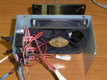
Main unit
The soldering station is based on an ATX power supply with a 12cm fan. I took such a terry Chinese for alteration. The declared power does not correspond to the filling at all, in fact, a block of 200 watts. But for our purposes, the consumption at the peak of two soldering irons will not exceed 140 watts.

From the top I placed two temperature controllers, separately for each soldering iron. And three switches allow you to separately turn on each soldering iron and an external 24v load. The general inclusion of the unit was left on the standard switch of the ATX unit. The power cable is also connected to the standard connector. Additionally, he brought out 24v power connectors and a USB block for connecting a 5v load.

12cm fan in addition to blowing the block, I use it to extract smoke. To increase the airflow, in addition to the fan inside the case, another fan is installed on the outside. It is advisable to use fans with a power of more than 4W. I got a 12cm 220V 8W fan that I used as an external one. To power the 12v fan, a KREN8B linear stabilizer is used, installed through an insulating gasket on a low-voltage diode radiator. It lowers the voltage of 24V to 12, at the same time, together with the fan, it serves as the load of the power supply at idle. When using 2 powerful 12V fans, it is advisable to use a switching step-down stabilizer (the cost of a finished board for a current of about 2A on Ali is about $ 1). As a last resort, if using a linear regulator, mount it on a separate heatsink. On the front of the external fan there is a grid from the power supply fan, on top of which there is an air filter. I used a piece of a filter from a kitchen hood, it has a sorbent as part of the fiber. You can also look for pure carbon filters, unfortunately I have not yet come across suitable sizes.
I will not dwell on the alteration of the ATX block in detail, since the refinement depends on the model of the power supply. My block was built on the basis of the 3845 chip. I removed all the elements of non-12V channels and all the elements of regular filters and secondary power capacitors. Soldered a new filter using higher voltage capacitors. I was lucky that at the maximum the unit gave out 29v, and to get 24v I only had to pick up the resistance of the resistors in the stabilization circuit, and block the voltage protection circuits.

On the rear grill you can see the 24V terminals and the USB bar taken from the old case. The holes were made simply by biting out the elements of the lattice.
Soldering iron design
The design was considered in the previous article. Now I will show the manufacturing steps again and in more detail.
Connections of wires on twisting and heat shrinkage.
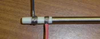


And also, relative to the last time, I somewhat changed the gluing of the paper. This time, I made the increase in the area of the layers gradual, which facilitated gluing.


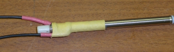
Shrink the heat shrink on top.

Behind to increase rigidity filled with glue.

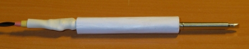
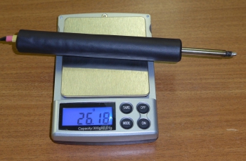
The soldering iron handle is light 26 gr. The distance from the sting is not large, only 4.5 cm.
This design can be used for at least a second soldering iron, for example, making it based on a T12-K or T12-KF tip, which are convenient for desoldering components and microcircuits.
I also met this option on the network: a person soldered wires to contacts, and made a handle from wood.
Temperature controller circuit
This time I made a circuit based on the LM324. (a circuit based on the LM358 is shown last time).
The Chinese version of the circuit taken as a basis should also be workable, the only thing you need to do is put a protective diode of the 1N4148 type in parallel with the capacitor C4, as in the circuit on the LM358, and the field-effect transistor must have an allowed gate voltage of more than 25 V.

The main difference between this circuit and the circuit on the LM358 is that the voltage from the thermocouple is first amplified, and only then it is applied to the comparator. My schematic is a compilation of a previous LM358 device and a Chinese LM324 schematic.

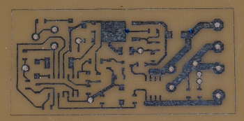
I drew the board in Sprint-Layout version 5. Variable resistor VSP4-1 0.5W, SMD resistors and ceramic capacitors of size 0805, except for R3 of size 2512 and R8 of size 1206, capacitor C7 of size B. The layout of the board is not perfect, but I needed something in size and fit, it coincided with the previous board. Diode D3 serves to protect against incorrect switching on and, in principle, it is not needed if the board is not used autonomously, but in the process of debugging I managed to turn on the board incorrectly in polarity, as a result, after a few seconds, capacitor C5 pulled, and the rest of the board remained intact. Resistor R3 can be replaced with a simple jumper. Resistors R1 and R2, together with a trimmer resistor, determine the range of temperature adjustment, unfortunately the zero drift spread of the operational amplifier does not allow you to accurately select the values of these resistors. My adjustment range is set from 200 to 400 degrees.

The board was made on a two-sided textolite, one of the sides is used underground. Jumpers are soldered into the contacts indicated on the diagram as with metallization, the rest are countersunk. But the board can also be made using a one-sided textolite, then jumpers are thrown from all points indicated by metallization with wires to a point located next to the negative terminal of the C5 electrolyte (it is advisable to make changes to the board by adding additional sites there). I cut the board to the right size after etching the drilling and tinning, because at the edges where I cut with scissors, the foil is deformed and does not clean well.
After desoldering the SMD parts, I washed the board, and only then unsoldered the variable and trimmer resistors, as well as the DIP parts with wires. This allows you to be less limited in the choice of fluxes when soldering SMD.

I solder the rest of the parts and wires using alcohol rosin or, more recently, no-clean flux. (Due to problems with the sting during debugging and have not yet understood the reasons, I tortured the board with soldering a little.)

In general, the circuit on the LM324 works a little better than on the LM358, although the differences are not very noticeable when soldering. The circuit on the LM358, when approaching the stabilization temperature, lights up with an LED for about a second, i.e. approach occurs smoothly with a drop in power delivered to the heater near the stabilization temperature. The circuit on the LM324 enters the stabilization mode more sharply almost immediately, switching to a slow flashing of the LED. Which circuit to choose for implementation should rather determine which parts are at hand, as I said when soldering, I did not notice much difference, although the circuit on the LM324 behaves better.
Plans
Or what he wanted to do and has not yet realized, as they say, there is nothing more permanent in the world than what has been done temporarily.
I'm thinking of putting soldering iron connectors. So that you can make more soldering irons for other tips and, if necessary, change the connected soldering irons. Now there are two mini-jacks on the case, but I am afraid to use them for a current of three amperes.
Put a fuse on external 24V connectors and possibly also for USB outputs.
Well, you need to look for how to replace the old exhaust filter, otherwise it is already dirty, and the air passes with difficulty.
It would also be nice to make some kind of new stand for both soldering irons.
It is necessary to install a small visor on the fan to direct the air flow and improve the suction of smoke.
As a continuation of the idea of a visor, I am thinking of attaching a magnifying glass with illumination there, but this is completely from distant plans.
List of radio elements
| Designation | Type | Denomination | Quantity | Note | Shop | My notepad |
|---|---|---|---|---|---|---|
| U1 | Operational amplifier | LM324 | 1 | To notepad | ||
| U2 | Linear Regulator | LM317 | 1 | To notepad | ||
| Q1 | bipolar transistor | 2N2222A | 1 | To notepad | ||
| Q2 | MOSFET transistor | AO4407A | 1 | To notepad | ||
| D1, D2 | rectifier diode | 1N4148 | 2 | To notepad | ||
| D3 | rectifier diode | 1N4007 | 1 | To notepad | ||
| C1 | Capacitor | 2.2 nF | 1 | To notepad | ||
| C2, C4, C6 | Capacitor | 0.1uF | 3 | To notepad | ||
| C3 | Capacitor | 1 uF | 1 | To notepad | ||
| C5 | Capacitor | 220uF X 35V | 1 | To notepad | ||
| C7 | Capacitor | 10uF X 16V | 1 | To notepad | ||
| C8 | Capacitor | 0.33uF | 1 | To notepad | ||
| R1 | Resistor | 8.2 kOhm | 1 | To notepad | ||
| R2 | Resistor | 1.5 kOhm | 1 | To notepad | ||
| R3 | Resistor | 75 ohm | 1 | To notepad | ||
| R4 | Resistor | 120 kOhm | 1 | To notepad | ||
| R5, R6 | Resistor |
High-quality professional equipment for soldering micro-components costs a lot of money, and inexpensive hot air guns are not suitable for most tasks. A lot of repairmen and radio amateurs from time to time encounter low-quality hot air guns for soldering.
To avoid such misunderstandings, it makes sense to make a soldering dryer with your own hands. This option is perfect for repairmen and radio amateurs who have specific equipment requirements and a very limited budget.
Before you start designing a homemade blow dryer, you should familiarize yourself with the basic methods of using this tool.

Soldering iron drawing.
A hot air gun for soldering, as a rule, may be needed in such cases:
- Soldering very small parts in SMD packages.
Most small radio components cannot be soldered with a soldering iron. To mount such components, it is necessary to tin the landing site, lubricate it with flux and position the microcircuit. After that, you can safely start heating the mounting contacts with a hair dryer until the solder under the component melts and it sits on the printed circuit board. - Lack of free space for using a soldering iron.
With a very dense arrangement of elements on a printed circuit board, the use of a soldering iron is significantly difficult. In this case, a hot air gun is the best option for a radio amateur. - Repair work related to mobile phones or tablet computers.
Most modern gadgets are almost impossible to disassemble without the use of a hot air gun. For example, replacing a screen on any phone requires preheating the old matrix with a hot air gun. Severe heat will neutralize the adhesive and allow the screen to separate from the body of the device. - Removal of BGA chips from landing pads.
Work on reballing and warming up modern video chips is carried out using a soldering hot air gun.
The temperature and air flow density control is usually carried out using the buttons on the hot air gun.
Using a soldering hot air gun involves the following steps:
- applying or solder paste to the place of intended installation;
- installation of a microcircuit on a seat;
- heating the mounting contacts with a soldering hot air gun.
In order to protect nearby components from heating, special aluminum foil shields should be placed on them.
After carrying out the work, you should check the quality of the soldering of all contacts with a needle.
Dismantling the element with a hair dryer is even easier. To remove a faulty chip, you must:
- evenly warm all contacts;
- gently remove the element with tweezers or suction cups.
When heating the surface with a hot air gun, it is necessary to make circular movements. This technique avoids local overheating of the board and violation of its geometry.
equipment requirements

Electric circuit soldering dryer.
The main requirements for a hot air gun for soldering microcircuits with your own hands are:
- Compliance with temperature regimes of soldering.
Most soldering work is carried out within 190 - 250 degrees Celsius. The bottom bar is for lead-containing solders, and the top bar is for factory-made lead-free solders. The soldering hot air gun must produce a stream of air at a strictly specified temperature in order to protect the microcircuits from overheating and failure. - Stable air flow.
With uneven air flow, working with soldering equipment is seriously difficult. - Safety and ease of use.
A thermal dryer should not overheat and pose a danger to the master. Ideally, a powerful do-it-yourself soldering iron should be designed on the basis of a transformer power supply.
The device must contain exclusively safe elements. In the manufacture of a home-made compressor power supply, special attention should be paid to the reliability of the design and its safety for others.
As experience shows, many craftsmen manage to make full-fledged working thermal tools from a building hair dryer, a household hair dryer, or even an ordinary soldering iron.
Soldering iron hair dryer

Schematic diagram of a blow dryer.
Before you make a soldering dryer with your own hands, you should:
- consider an air supply device;
- assemble a special heating element;
- equip the equipment with thermocouples;
- consider a system for monitoring the current temperature of the equipment.
When considering how to make a soldering iron from a conventional soldering iron, you should take into account all the subtle points so as not to expose yourself to excessive risk.
The main criteria that a soldering iron-based thermal device must meet are:
- temperature control;
- normal heater power;
- safe compressor.
Installation of a blower for a DIY soldering station is recommended to be done in accordance with current electrical safety regulations. Such a connection of the equipment will ensure that there is no interference in the electrical network.
What you need to create a hairdryer from a soldering iron?
When creating a soldering dryer with your own hands, you should prepare:
- an ordinary old soldering iron powered by AC;
- a quartz tube to create a heating chamber for the air flow of a hair dryer;
- a halogen lamp for spotlights for warming up the air and melting the flux with a hairdryer;
- nichrome wire up to 0.7 mm thick;
- thermostat;
- soldering iron fan.

Schematic diagram of a soldering iron.
All equipment must be connected to specially prepared connectors, the pinout of which depends on the manufacturer of the soldering equipment.
The process of assembling a hair dryer from a soldering iron
A homemade hair dryer of microcircuits from an old soldering iron is assembled in several stages:
- Laying a homemade nichrome wire spiral inside a quartz tube.
- Connecting the spiral to the power wire.
- Threading a thermocouple wire to control the temperature of the filament.
- Insulation of the device with a layer of tube wound on a quartz tube.
- Installing the tube in the handle of the soldering iron, instead of a sting.
- Centering the tube by wrapping it with an asbestos cord.
- Clamping the front outlet of the tube with a clip.
- Passing the airflow hose.
- Connecting a compressor that creates an air flow.
The temperature regulator of the heating source is best placed on the body of the hot air gun.
The principle of operation of a hot air gun based on a soldering iron is as follows:
A small current is applied to the nichrome filament, causing it to heat up. The air coming from the compressor is collected in a special insulated chamber and heated under the action of a spiral and insulating foil. After that, the air leaves the heating chamber and enters directly to the printed circuit board.

Soldering dryer - drawing for manufacturing.
Unfortunately, this method of making a thermal hair dryer has a lot of disadvantages.
The disadvantages of a hot air gun made from a conventional soldering iron include:
- difficulties with temperature calibration;
- adjustment of the force of the air flow is carried out by pinching the air tube;
- the inability to adjust the intensity of heating in most conventional soldering irons;
- the complexity of the work;
- poor thermal insulation of the device.
In most cases, the manufacture of a thermal hair dryer from a soldering iron is not justified. Converting an inexpensive building hot air gun is a much more efficient method of making a hot air gun for soldering micro-components.
Conclusion
There are a huge number of instructions on the Internet how to make a hair dryer. Most methods for making a hot air gun are based on reworking existing equipment, such as a building hot air gun, a household hair dryer, or a conventional soldering iron with a metal tip.
In many cases, if you need to use a soldering hot air gun, you should think about purchasing the appropriate station. A hot air gun connected to the soldering station provides data on the current temperature of the air flow and allows you to calibrate the thermocouple.
It is most likely not worth explaining how much a soldering station is necessary for the operation and repair of modern electronic equipment, just wasting time. Unfortunately, even the most budget options for such equipment cost a lot of money, from 10 thousand rubles and more, so to work at home you have to look for options for making a soldering station with your own hands. This is not an easy task, requiring patience in debugging and setting up the control component of the soldering station.
Options for building a soldering station
Among any useful and not very set of information available on the network, you can find a lot of home-made circuits and devices, up to options for making home-made thermocouples and hair dryers. In practice, for soldering and warming up the electronic components of motherboards and video cards of computers, control stations and other microprocessor equipment, two types of installation are most often used:
- A design that works on the principle of heat transfer by hot air. Assembling such a hot-air soldering station with your own hands is quite simple, but under one condition, most of the components must be bought ready-made, and not attempted to be made in a handicraft way;
- The non-contact installation works on the principle of a heat emitter. Do-it-yourself infrared soldering station is assembled on the basis of powerful halogen lamps and a system of reflectors. To control the heating, the software capabilities of the laptop are used.
The coolest soldering station, the performance of which is confirmed in practice, is recognized as an installation made of a reflective mirror and a powerful 500W halogen lamp.

For your information! With the correct setting of such a soldering station, it was possible to solder the contacts with hard silver solder.
But for soldering or heating, such a device will be deadly, because the main criterion when choosing a soldering station option should be the controllability of surface heating with an accuracy of 1 ° C.
Building a low power air soldering station
The design of the soldering station consists of four main elements:
- Heating process control boards;
- Corps;
- Power supply;
- Hairdryer and soldering iron.
The power supply and case are selected in accordance with the available resources. The rest of the nodes will have to be bought or made by hand.
Main working tool of air soldering station
The main working body of the soldering station is a hair dryer with an electric spiral and a cooler that blows hot air onto the surface of the solder or microchip. Its device is simple, and if desired, you can wind a nichrome spiral from an ordinary low-voltage soldering iron onto a ceramic tube.
The heating element is insulated with several layers of fiberglass. Nichrome will not heat up to the state of hot metal, but it is necessary to insulate the surface at least so that the metal surface does not oxidize. At the outlet of the heating device, it is necessary to install a ceramic ring or nozzle with a diameter of 8-10 mm. Heat-resistant chips that fix the heating coils in old irons are best suited. The heater power for the soldering station will be required in the range of 400-500W, no less.

To organize pressurization, you can use a cooler from a computer, or take as a basis a case with an engine and a fan from a camping hair dryer. But in this case, you will have to develop your own version of controlling the engine speed and air flow pressure.

Advice! There are many manual control schemes in which it is proposed to organize the air supply to the heating element using an external compressor.
From practice, we can say that the air supply control of the soldering station should only be automatic, otherwise turning the pressure bypass valve on and off will make the soldering process real flour, and not work.
In addition, a thermocouple must be installed in the design of the hair dryer, with the help of which, in fact, the air temperature is regulated.
The connection diagram of the hair dryer can be done as shown in the figure below.

The quality of the soldering depends on how convenient and safe the design of the hair dryer is to work, so if you don’t want to fool around with homemade products, you can buy a regular hair dryer from the Luckey desktop soldering station, model 702, and simply adapt it to the control board.

Soldering Station Control System
From the list above, the most difficult node for a do-it-yourself soldering station is the control board. You can buy it ready-made, but if you have experience in building such structures, you can easily assemble the circuit with your own hands, a set of parts can be ordered online.
Of all the existing options available online, the circuit based on the ATMEGA 328p controller is recognized as the most reliable and easy to use. The board is assembled on the basis of the diagram below.
The assembly is carried out on a fiberglass board, and with normal assembly quality, the soldering station control system starts on the first try. When assembling the board, you will need to be extremely careful when soldering the elements, especially the power circuit of the chip, making a ground and trying not to overdo it with heating the legs. But, first of all, it will be necessary for the programmer to hammer in the program control code. As a soldering station power supply, a 24V-6A impulse switch with built-in overload protection is used.

The control circuit of the soldering station uses a pair of powerful IRFZ44N mosfets, measures must be taken to protect against overheating and burnout. If the heater of the hair dryer turned out to be too powerful, it is quite possible that the power supply blocking will work.
It is desirable to bring the simistor and optoelectronic pair to a separate board, and be sure to install a cooling radiator. For an optocoupler, it is recommended to use relatively low-power control LEDs with a maximum current consumption of up to 20 milliamps.
The design of the soldering station uses a five-pin soldering iron with a power of 50 watts. The developers recommend using Arrial 936, but you can install any similar tool with a pre-installed thermocouple.
Assembly and adjustment of the station
All elements are mounted in a closed die case from an old power supply, a radiator and a switch are placed on the back wall, and a temperature indicator is on the front.
The soldering station is controlled by three variable resistances per 10 kOhm. The first two regulate the temperature of the soldering iron and hair dryer, the third sets the speed of the hot air fan.
The adjustment process only concerns adjustment of the heating temperature of the soldering iron and hot air gun on the board of the soldering station. To do this, we connect the power to the soldering iron and use a thermocouple with a tester to measure the actual temperature of the heating tip. Next, using a trimming resistor, we display the reading on the digital indicator of the station in accordance with the data of the tester. In a similar way, we measure the temperature of the air flow of the hair dryer and adjust the readings on the indicator with a trimmer. If you turn up the fan speed of the hair dryer, then the place of soldering can be easily heated up to 450 ° C.

Making an infrared soldering iron
Soldering stations operating on infrared radiation, with rare exceptions, are used to warm up a soldered processor, bridge or processor on a video card. As you know, processors do not tolerate overheating very well, and often, under heavy load and poor heat dissipation, the low-temperature solder of the contacts from the pad is soldered.

One of the barbaric ways to restore contact is to warm up the "body" of the processor with dosed thermal radiation. This can be done with an ordinary hair dryer or even an iron, but after such procedures a positive effect is achieved in one of three cases. Therefore, homemade specialists prefer to build infrared heating soldering stations.
Manufacture of housing and heating elements
Structurally, the soldering station consists of four main elements:
- Lower heating block;
- Upper heating block;
- Stand and heater control unit.
Between the upper and lower cases, the computer motherboard is placed so that the infrared stream from the upper heating system is directed mainly to the target - the processor case. The rest of the board is covered from heat with an aluminum plate or foil with a cut-out window for the processor.

The lower body of the soldering station is used to create a thermal shield, in other words, to additionally heat the board in order to reduce heat loss due to air convection.
Important! The whole trick of the soldering station is to make the heating not only efficient, but also controllable, that is, the case cannot be allowed to overheat, so the design uses a thermocouple and a halogen control interface.
As heaters, you can use an ordinary nichrome spiral laid inside quartz tubes or R7S J254 halogens.

For the manufacture of the body of the lower block, you can use any steel box that is suitable in size, on which lamp connectors are installed. As a result, after assembling and connecting the wiring, the design of the soldering station is obtained, as in the photo.

The upper heating block is made in a similar way.
The whole device and control is mounted on a tripod from an old Soviet photographic enlarger, which has a height adjustment of the upper unit. It remains to assemble the control system of the soldering installation.

Thermocouples and control
In order to prevent overheating, the soldering station uses two thermocouples - for the processor case and the rest of the motherboard. To control the soldering station, the Arduino MAX6635 interface board is used, which is connected to the serial port of a home laptop or PC, for which you have to look for the appropriate software content or make it yourself.

The soldering station is controlled as follows. The computer receives information about the temperature through the interface and a thermocouple and changes the heat flux power with the help of on-off pulses of the station's halogens. As it overheats, the duration of the burning period of the lamp will be reduced, and when it cools down, on the contrary, it will be increased.
When assembled, the soldering station looks like in the photo. The construction cost was just over $80.
Conclusion
There are at least four more options for manufacturing a soldering iron, including one of them of a battery type. Which one is the most convenient to operate can only be established in a practical way, after the construction of a full-size soldering iron. The two soldering system diagrams presented in the article are the simplest and most affordable to manufacture with a very modest budget of $ 150.
Modern microcircuits are miniature in size. To carry out repair and installation work in them, craftsmen need a special tool with the ability to regulate soldering modes. For this, a soldering station is used. It is not cheap, so the craftsmen are faced with the question of how to make a soldering station with their own hands. For an experienced master, this will not be difficult. The main difficulty is in the correct configuration of the device made.
Ways to design a soldering station
Each radio amateur can come up with an original station design, which is confirmed by the numerous options posted on the network. But all devices can be combined into two groups:
- Using the principle of hot air for heat transfer - the simplest design;
- Applying thermal radiation from an infrared source. High power halogen lamps are used as emitters, to which reflective elements are added.
Structural nodes of the soldering station
A homemade soldering station using a hair dryer consists of the following structural elements:
- a microcircuit that controls heating;
- soldering iron;
- electric hair dryer;
- power unit;
- outer casing.
The main element of the soldering station is a hair dryer, consisting of a heating coil and a cooler. When designing it, the following features are taken into account:
- The nichrome spiral is wound on a ceramic rod and insulated with fiberglass to prevent oxidation;
- To create an air flow, a narrow nozzle is made at the outlet, with a diameter of about 0.5 cm. You can put a bushing made of fire-resistant material;

- Heating power is provided not less than 0.4 kW;
- A computer cooler is suitable as a fan;
- A thermocouple must be included in the assembly circuit to control the temperature regime.
Important! The fan should be controlled automatically, restarting it manually will make the soldering process impossible.
- When a do-it-yourself soldering station is assembled, special attention is paid to the control scheme. The simplest solution is to buy a chip in a store, for example, ATMEGA 328r. When self-assembling the circuit, a fiberglass board is used. Soldering should be done with the utmost care, trying to avoid excessive heating;

- The power source can be a 24 V switching power supply, provided with overload protection. The circuit elements are powerful MOS transistors, which are thus protected from excessive heating;
Important! The optoelectronic pair, together with the triac, is placed on a separate board, a cooling radiator is also located there. The LEDs used must not be rated for currents greater than 20 mA.
- The choice of soldering iron is based on the power of 50 W and the presence of a thermocouple.
A suitable metal casing is selected for mounting the station controls inside it. A radiator with a switch will be placed on the back of the casing, a temperature indicator on the front.
Heating of a hair dryer, soldering iron, blowing power are adjusted using controlled resistors (10 kOhm).

The final stage is the adjustment of the assembled device. A thermocouple with a temperature sensor is taken, and the real heating of the soldering iron tip is measured. The same temperature value must be set on the indicator of the soldering station using a resistor. An identical procedure is carried out with a hairdryer.
An infrared soldering station is necessary when repairing BGA chips or computer processors. The device consists of upper and lower heating sections and a control unit. The board for soldering is placed between the heating sections, where the main heating function is performed by the upper one, and the lower one serves as an additional thermal screen.

The heaters are halogen lamps, for which the connecting connectors are mounted in the selected metal case. An identical design is assembled for both sections, the difference is only in size. A tripod or other movable mechanism is used to mount the upper section. Heating is controlled by thermocouples.
The heaters are controlled by an Arduino MAX6635 chip connected to a PC. The main difficulty is finding the right software.
These are just two ideas for self-assembly of a soldering station, which can be improved or proposed new. Creativity and skillful hands will save radio amateurs from additional financial expenses and provide them with convenient tools for work.
Video
I have long wanted to buy a station, but due to financial problems, the opportunity did not arise and after a little thought I decided - can it be done by hand?
I rummaged a little on the net and found this video https://www.youtube.com/watch?v=wzGbTwlyZxo. The station is just what I need - microcontroller control, data output to the 16x2 LCD display, on which it is displayed.

The top line - the set temperature of the soldering iron and the current temperature on it, the data is updated several times per second (0-480gr)
The bottom line - the set temperature of the hair dryer, the current temperature on it (0-480g), as well as the rotation speed of the fan built into the hair dryer (0-99)


Board and Schematic
You can download the printed circuit board (+ diagram and firmware), everything is original, like the author's.
A few tips for those who are too lazy to watch videos (although I explained everything in some detail in them)
The dimensions of the printed circuit board are already set, there is no need to mirror either. It is advisable to replace the terminals through which the controls are connected to the board, that is, instead of the terminals, use the usual method - take the wires and solder them into the corresponding holes on the board.
During etching, it is MANDATORY to check the sections of the board with the template, since in some places the pins of the SMD components can form a short circuit, all this is clearly visible in the photo

The ATMEGA328 type MK is the same microcontroller that costs a penny in China on programmer boards with an arduino uno kit, but with MK you will need either a home-made programmer or a native arduino uno, as well as a 16 MHz quartz resonator.

MK is fully responsible for the control and output of data on the LCD display. The control of the station is quite simple - 3 variable resistors per 10 kOhm (the most common, mono - 0.25 or 0.5 watts) are the first responsible for the temperature of the soldering iron, the second is the vein, the third increases or decreases the speed of the cooler built into the hair dryer.


The soldering iron is controlled by a powerful field-effect transistor, through which a current of up to 2 Amperes will flow, therefore it will heat up, the triac will also heat up - it, together with a transistor and a 12-volt stabilizer, was brought to a common heat sink by wires, additionally insulated the cases of these components from the radiator.


Be sure to take 3mm LEDs with low consumption (20mA) due to the use of more powerful 5mm LEDs (70mA), the hair dryer did not work for me, or rather, there was no heating. The reason is that the LED on the board and the LED that is built into the optocoupler (it actually controls the entire heating unit of the hair dryer) are connected in series and there was simply not enough power for the LED in the optocoupler to light up.


soldering iron
I myself took a Ya Xun soldering iron for stations of this type 40 watts with a durable tip. The plug has 5 pins (contact holes), the pinout of the plug is below

Keep in mind that the photo shows the pinout of the plug, which is on the soldering iron itself,
The soldering iron has a built-in thermocouple, the data from which is received and decoded by the station itself. You DO need a soldering iron with a thermocouple, not a thermistor as a temperature sensor.


The thermocouple has polarity, if the thermocouple is connected incorrectly, the soldering iron will reach the maximum temperature after turning on and become uncontrollable.

In principle, the power can be from 350 to 700 watts, I advise no more than 400 watts,
more than enough for any need. The hair dryer also has a built-in thermocouple as a temperature sensor. The hair dryer must be with a built-in cooler. It has an 8-pin socket, the pinout of the socket on the hair dryer is shown below.


Inside the hair dryer there is a 220-volt heater itself, a thermocouple, a fan and a reed switch, the latter can be thrown out immediately, it is not needed in this project.
The heater has no polarity, but the thermocouple and the cooler do, so observe the polarity of the connection, otherwise the motor will not spin, and the heater will reach the maximum temperature and become uncontrollable.
power unit
Any (preferably a stabilized adapter) 24 volts minimum 2 amps, advice - 4-5 amps. Universal chargers for laptops are perfect, in which it is possible to adjust the output voltage of 12 to 24 Volts, protection against short circuits and a stabilized output - but it costs a penny, I chose this one myself.

You can also use a low-power power supply for 24 Volt LED strips, available with a current of 1 Ampere or more.

You can also slightly modify the electronic transformer (as the most budget option) and implement it in the circuit, I explained in more detail about the power supplies at the end of the video (part 1)
You can also use a transformer power supply - it may not be stabilized, but I repeat - it is desirable to have stabilization.
Mounting and housing
The body is from a Chinese radio, the 16x2 display fits perfectly, all controls are installed on a separate plastic sheet and docked to the bottom of the radio.


The main power components are reinforced on the heat sink, through additional insulating gaskets and plastic washers. The heat sink is taken from a non-working uninterruptible power supply.


It heats up, but only after long work with a hair dryer at high power, but all this is tolerable, by the way - the board provides an additional 12 volt output for connecting a cooper, so that you can blow off the radiator if you need it.


Setting
In principle, to set up, you need either a thermometer or a tester with a thermocouple and the ability to measure temperature.


First you need to set a certain temperature on the soldering iron (for example, 400g), then press the thermocouple to the soldering iron tip in order to understand the real temperature on the tip, and then simply using the trimming resistor on the board (slow rotation) we achieve to compare the actual temperature on the soldering iron (which is displayed) with the one shown by the thermometer.