DIY welding semiautomatic device from latra 9a. DIY welding transformer on a magnetic circuit from latrov
I am sure: from a compact and at the same time quite reliable, cheap and easy-to-manufacture "welder" not a single artisan, homely owner will refuse. Especially if he finds out that this apparatus is based on a 9-ampere laboratory autotransformer LATR2, which is easily modernized (familiar to almost everyone from school physics lessons) and a home-made thyristor mini-regulator with a rectifier bridge. They make it possible not only to safely connect to a 220 V AC household lighting network, but also to change u on the electrode, and therefore, to select the required welding current value.
The operating modes are set using a potentiometer. Together with capacitors C2 and C3, it forms phase-shifting chains, each of which is triggered during its half period. opens the corresponding thyristor for a certain period of time. As a result, the primary winding of the welding T1 turns out to be adjustable 20-215 V. Transforming in the secondary winding, the required -u makes it easy to ignite the arc for welding on alternating (terminals X2, X3) or rectified (X4, X5) current.
Resistors R2 and R3 bypass the control circuits of the thyristors VS1 and VS2. Capacitors C1. C2 is reduced to an acceptable level of radio interference accompanying an arc discharge. A new lamp with a current-limiting resistor R1 is used in the role of the HL1 indicator light, signaling that the device is switched on to the household power grid.
To connect the "welder" to the apartment wiring, a conventional plug X1 is used. But it is better to use a more powerful electrical connector, which is commonly called “Euro plug-Euro socket”. And as a switch SB1, a VP25 "bag" is suitable, designed for a current of 25 A and allowing you to open both wires at once.
As practice shows, it makes no sense to install any kind of fuses (anti-overload machines) on the welding machine. Here you have to deal with such currents, when exceeded, the protection at the input of the network into the apartment will necessarily work.
For the manufacture of the secondary winding from the base LATR2, remove the casing, the current slider and the fastening fittings. Then, on the existing 250 V winding (127 and 220 V taps remain unclaimed), reliable insulation is applied (for example, made of varnished cloth), on top of which a secondary (step-down) winding is placed. And this is 70 turns of an insulated copper or aluminum bus, having a diameter of 25 mm2. It is acceptable to perform the secondary winding from several parallel wires with the same overall cross-section.
Winding is more convenient for two people. While one, trying not to damage the insulation of adjacent turns, carefully pulls and lay the wire, the other holds the free end of the future winding, protecting it from twisting.
The upgraded LATR2 is placed in a protective metal casing with ventilation holes, on which a circuit board made of 10-mm getinax or fiberglass with a packet switch SB1, a thyristor voltage regulator (with a resistor R6), a light indicator HL1 for connecting the device to the network and output terminals for welding on alternating (X2, X3) or constant (X4, X5) current.
In the absence of a basic LATR2, it can be replaced with a home-made "welder" with a magnetic circuit made of transformer steel (core section 45-50 cm2). Its primary winding should contain 250 turns of PEV2 wire with a diameter of 1.5 mm. Secondary is no different from that used in the modernized LATR2.
At the output of the low-voltage winding, a rectifier unit with power diodes VD3 - VD10 is installed for direct current welding. In addition to these valves, more powerful analogs are quite acceptable, for example, D122-32-1 (rectified current - up to 32 A).
Power diodes and thyristors are installed on heat sinks, heat sinks, each with an area of at least 25 cm2. The axis of the adjusting resistor R6 is brought out from the casing. A scale with divisions corresponding to specific values of direct and alternating voltage is placed under the handle. And next to it is a table of the dependence of the welding current on the voltage on the secondary winding of the transformer and on the diameter of the welding electrode (0.8-1.5 mm).
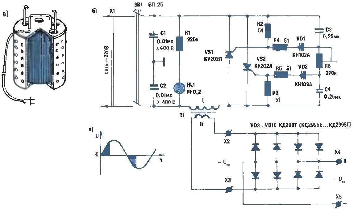
A welding transformer based on the widespread LATR2 (a), its connection to the circuit diagram of a home-made adjustable device for welding with alternating or direct current (b) and a voltage diagram (c), explaining the operation of the resistor regulator of the electric arc combustion mode.
Of course, homemade electrodes made of carbon steel "wire rod" with a diameter of 0.5-1.2 mm are also acceptable. Workpieces with a length of 250-350 mm are covered with liquid glass - a mixture of silicate glue and crushed chalk, leaving unprotected 40-mm ends required for connecting to a welding machine. The coating is thoroughly dried, otherwise it will start "shooting" during welding.
Although for welding you can use both alternating (terminals X2, X3) and constant (X4, X5) current, the second option, according to welders' reviews, is preferable to the first. Moreover, polarity plays an important role. In particular, when the "plus" is applied to the "ground" (welded object) and, accordingly, the electrode is connected to the terminal with the "minus" sign, the so-called forward polarity takes place. It is characterized by the release of more heat than with reverse polarity, when the electrode is connected to the positive terminal of the rectifier, and the "mass" - to the negative. Reverse polarity is used when it is necessary to reduce the generation of heat, for example, when welding thin metal sheets. Almost all the energy released by the electric arc is spent on the formation of a weld, and therefore the penetration depth is 40-50 percent greater than with a current of the same magnitude, but of straight polarity.
And a few more very significant features. An increase in the arc current at a constant welding speed leads to an increase in the penetration depth. Moreover, if the work is carried out on alternating current, then the last of the named parameters becomes 15-20 percent less than when using direct current of reverse polarity. The welding voltage has little effect on the penetration depth. But the width of the seam depends on uw: with increasing voltage, it increases.
Hence, an important conclusion for those involved in, say, welding when repairing a car body made of thin sheet steel: the best results will be obtained by direct current welding of reverse polarity at a minimum voltage (but sufficient for stable arc burning).
The arc must be kept as short as possible, the electrode is then consumed evenly, and the penetration depth of the metal being welded is maximum. The seam itself turns out to be clean and durable, practically free of slag inclusions. And you can protect yourself from rare splashes of the melt, which are difficult to remove after the product has cooled down, by rubbing the heat-affected surface with chalk (the drops will roll off without adhering to the metal).
Excitation of the arc is carried out (having previously applied to the electrode and "mass" corresponding to Ucv) in two ways. The essence of the first is in a light touch of the electrode to the parts to be welded, followed by its removal by 2-4 mm to the side. The second method resembles striking a match over a box: sliding the electrode over the surface to be welded, it is immediately taken away a short distance. In any case, you need to catch the moment of the arc and only then, smoothly moving the electrode over the seam formed immediately, maintain its quiet combustion.
Depending on the type and thickness of the metal to be welded, one or another electrode is selected. If, for example, there is a standard assortment for a St3 sheet with a thickness of 1 mm, electrodes with a diameter of 0.8-1 mm are suitable (this is basically the design in question). For welding on 2-mm rolled steel, it is desirable to have a more powerful "welder" and a thicker electrode (2-3 mm).
For welding jewelry made of gold, silver, cupronickel, it is better to use a refractory electrode (for example, tungsten). It is possible to weld less oxidation-resistant metals using carbon dioxide protection.
In any case, the work can be performed both with a vertically located electrode, and tilted forward or backward. But sophisticated professionals say: when welding with an angle forward (meaning an acute angle between the electrode and the finished seam), a more complete penetration and a smaller width of the seam itself are provided. Welding with a backward angle is recommended only for overlapping joints, especially when you have to deal with profile rolled products (angle, I-beam and channel).
An important thing is the welding cable. For the device under consideration, a copper stranded (total cross-section of about 20 mm2) in rubber insulation is the best fit. The required amount is two one and a half meter sections, each of which should be equipped with a carefully crimped and soldered terminal lug for connection to the "welder". For direct connection with the "mass", a powerful clip of the "crocodile" type is used, and with an electrode - a holder resembling a three-pronged fork. You can also use a car "cigarette lighter".
A good welding machine makes all metal work much easier. It allows you to connect and cut various pieces of iron, which differ in their thickness and density of steel.
Modern technology offers a huge selection of models, differing in power and size. Reliable designs have a fairly high cost. Budget options tend to have a short lifespan.

Our material provides detailed instructions on how to make a do-it-yourself welding machine. Before starting the work process, it is recommended that you familiarize yourself with the type of welding equipment.

Types of welding machine
The devices of this technique differ into several types. Each mechanism has some features that are reflected in the work performed.
Modern welding machines are divided into:
- DC models;
- with alternating current
- three-phase
- invector.

The AC model is considered the simplest mechanism that you can easily make yourself.

A simple welding machine allows you to perform complex work with iron and thin steel. To assemble such a structure, you must have a certain set of materials.

These include:
- wire for winding;
- core made of transformer steel. It is necessary for winding the welder.

All of these parts can be purchased from specialized stores. Detailed consultation of specialists helps to make the right choice.
AC design
Experienced welders call this a step-down transformer.

How to make a welding machine with your own hands?
The first thing to do is to make the right core. For this model, it is recommended to select the bar part type.

For its manufacture, you will need plates made of transformer steel. Their thickness is 0.56 mm. Before proceeding with the assembly of the core, its dimensions must be observed.

How to calculate the parameters of a part correctly?
Everything is simple enough. The dimensions of the center hole (window) must accommodate the entire winding of the transformer. The photo of the welding machine shows a detailed diagram of the assembly of the mechanism.

The next step is to assemble the core. For this, thin transformer plates are taken, which are interconnected to the required thickness of the part.

Next, we wind a step-down transformer consisting of turns of a thin wire. For this, 210 turns of thin wire are made. On the other hand, 160 turns are wound. The third and fourth primary windings should contain 190 turns. After that, a thick plate is attached to the surface.

The ends of the wound wire are fixed with a bolt. I mark its surface with the number 1. The next ends of the wire are fixed in a similar way with the application of the appropriate markings.
Note!


The finished structure should contain 4 bolts with a different number of turns.

In the finished structure, the winding ratio will be 60% to 40%. This result ensures normal operation of the device and good quality of the welding attachment.

You can control the supply of electrical energy by switching the wires to the required amount of winding. It is not recommended to overheat the welding mechanism during operation.
DC apparatus
These models allow you to perform complex work on thick steel sheets and cast iron. The main advantage of this mechanism is simple assembly, which does not take much time.

The welding invector is a secondary winding design with an additional rectifier.

Note!

It will be made of diodes. In turn, they must withstand an electric current of 210 A. For this, elements marked D 160-162 are suitable. Such models are often used to work on an industrial scale.

The main welding invector is made from a printed circuit board. Such a semiautomatic welding machine can withstand power surges during long-term operation.

Repairing the welding machine will not be difficult. Here it is enough to replace the damaged area of the mechanism. In the event of a serious breakdown, it is necessary to re-implement the primary and secondary windings.

Diy welding machine photo


Note!


Burnt LATRs (laboratory autotransformers) have long been a widespread material for the manufacture of home-made welding transformers. Inside the LATR body there is a toroidal autotransformer made on a magnetic circuit of a significant section. It is this magnetic circuit that will be needed from LATR for the manufacture of a welding transformer. A transformer usually requires two identical magnetic circuit rings from large LATRs.
LATRs are produced in different types, with maximum currents from 2 to 10A, not all of them are suitable for the manufacture of transformers for welding, only those with the size of the magnetic cores that allow you to lay the required number of turns. The most common among them is probably the LATR-1M autotransformer. Depending on the winding wire, it is designed for currents of 6.7-9A, although the dimensions of the autotransformer itself do not change from this. The LATR-1M magnetic core has the following dimensions: outer diameter D = 127 mm, inner diameter d = 70 mm, ring height h = 95 mm, section S = 27 cm 2, weight about 6 kg. A good welding transformer can be made of two LATR-1M rings, however, due to the small internal volume of the window, you cannot use too thick wires and you will have to save every millimeter of window space. A significant disadvantage of the LATR transformer, in comparison with the U-shaped transformer circuit, is also the fact that the coils cannot be made separately from the magnetic circuit. This means that you will have to wind, pulling each turn through the window of the magnetic circuit, which, of course, greatly complicates the manufacturing process.
There are LATRs with more voluminous magnetic drive rings. They are much better suited for making welding transformers, but less common. In other autotransformers, similar in parameters to LATR-1M, for example AOSN-8-220, the magnetic circuit has other dimensions: the outer diameter of the ring is larger, but the height and diameter of the window are smaller, d = 65 mm. In this case, the window diameter must be expanded to 70 mm.
The ring of the magnetic circuit consists of pieces of iron tape wound on top of each other, fastened along the edges by spot welding. In order to increase the inner diameter of the window, it is necessary to detach the end of the tape from the inside and unwind the required amount. But don't try to rewind everything in one go. It is better to unwind one turn at a time, cutting off the excess each time. Sometimes in this way the windows of larger LATRs are also expanded, although this inevitably decreases the cross-sectional area of the magnetic circuit.
In principle, a cross-sectional area and one ring would be sufficient for a welding transformer. But the problem is that smaller magnetic cores inevitably require more turns, which increases the volume of the coils and requires more window space.
Staggered shoulder transformer
At the beginning of the manufacture of the transformer, it is necessary to insulate both rings. In this case, special attention should be paid to the corners of the edges of the rings - they are sharp, they can easily cut the imposed insulation, and then close the winding wire with themselves. It is better to first smooth the corners a little with a file, and then apply some strong and elastic tape along it, for example, a dense keeper tape or a cambric tube cut along the length. On top of the rings, each separately, they are wrapped with a thin layer of fabric insulation.Then the insulated rings are connected together. The rings are tightly tightened with a strong tape, and on the sides they are fixed with wooden pegs, also then tightened with tape, - the magnetic core for the transformer is ready.
The next step is the most critical - laying the primary winding. The windings of this welding transformer are wound according to the scheme: primary in the middle, two secondary sections on the side arms.

The primary winding takes about 70-80 m of wire, which will have to be pulled through both windows of the magnetic circuit with each turn. In this case, you can not do without a simple device.

First, the wire is wound on a wooden reel and in this form is easily pulled through the ring windows.
The primary wire can have a diameter of 1.6-2.2 mm. For magnetic circuits made up of rings with a window diameter of 70 mm, you can use a wire with a diameter of no more than 2 mm, otherwise there will be little space for the secondary winding. The primary winding contains, as a rule, 180-200 turns at normal mains voltage, which is sufficient for efficient operation with a 3 mm electrode.
A cambric is put on the end of the wire, which is attracted by HB electrical tape to the beginning of the first layer. The surface of the magnetic circuit has a rounded shape, so the first layers will contain fewer turns than the next ones to level the surface.

The wire lays down coil to coil, in no case allowing the wire to overwhelm the wire. The layers of wire must be insulated from each other. Again, to save space, the winding should be placed as compactly as possible. On a magnetic core made of medium-sized rings, the interlayer insulation should be used thinner. One should not strive to wind the primary winding quickly. This process is slow, and after laying the hard wires, your fingers begin to ache. It is better to do this in 2-3 approaches - after all, quality is more important than speed.
If the primary winding is made, most of the work is done, leaving the secondary. But first you need to determine the number of turns of the secondary winding for a given voltage. To get started, connect the ready-made primary to the network. The no-load current of this version of the transformer is small - only 70-150 mA, the hum of the transformer should be barely audible. We wind 10 turns of any wire on one of the side arms and measure the output voltage across them. Each of the side arms accounts for half of the magnetic flux created on the central arm, so here 0.6-0.7V falls on each turn of the secondary winding. Based on the result obtained, the number of turns of the secondary winding is calculated, focusing on a voltage of 50V (about 75-80 turns).
The choice of material for the secondary winding is limited by the remaining space of the magnetic circuit windows. Moreover, each turn of a thick wire will have to be pulled along its entire length into a narrow window. The easiest way is to wind it with an ordinary stranded wire 16 mm 2 in synthetic insulation - it is soft, flexible, well insulated, and will only slightly warm up during operation. It is possible to make a secondary winding from several strands of copper wire.
Half of the turns of the secondary winding is wound on one shoulder, half on the other. If there are no wires of sufficient length, you can connect them from pieces - it's okay. Having wound the windings on both arms, you need to measure the voltage on each of them, it may differ by 2-3V - the somewhat excellent properties of the magnetic cores of different LATRs affect, which does not particularly affect the properties of the arc during welding. Then the windings on the shoulders are connected in series, but care must be taken that they are not in antiphase, otherwise the output will produce a voltage close to zero (see article Winding of a welding transformer). At a mains voltage of 220-230V, a welding transformer of this design must develop a current of 100-130A in arc mode. Short-circuit current of the secondary circuit - up to 180A.
It may turn out that it was not possible to fit all the calculated turns of the secondary winding into the windows, and the output voltage turned out to be lower than the desired one. The operating current will not decrease much from this. To a greater extent, lowering the no-load voltage affects the arc ignition process. The arc ignites easily at voltages close to 50V and above. Although the arc can be ignited without any problems at lower voltages. So if the manufactured transformer has an output of about 40V, then it can be used for work. It's another matter if you come across electrodes designed for high voltages - some brands of electrodes operate from 70-80V.
Toroidal transformer
On the LATR rings, you can also make a welding transformer according to a different - toroidal scheme. This also requires two rings, preferably from large LATRs. The rings are connected and insulated: one ring-magnetic circuit with a significant cross-sectional area is obtained.
The primary winding contains the same number of turns as in the previous circuit, but winds along the length of the entire ring and, as a rule, lies in two layers. The problem of the lack of internal space of the magnetic circuit window of such a transformer circuit is even more acute than for the previous design. Therefore, it is necessary to insulate here with as thin layers and materials as possible. Thick winding wires cannot be used here either. Although some installations use LATRs of particularly large dimensions, only one such ring can be used to manufacture a toroidal welding transformer.
The advantageous difference between the toroidal circuit for a welding transformer is a higher efficiency. Each turn of the secondary winding will now have more than one volt of voltage, therefore, the "secondary" will have fewer turns, and the output power will be higher than in the previous circuit. However, the length of the turn on the toroidal magnetic circuit will be longer, and it is unlikely that it will be possible to save on the wire here. The disadvantages of this scheme include: the complexity of the winding, the limited volume of the window, the inability to use a wire of large cross-section, as well as the high intensity of heating. If in the previous version all the windings were separate and at least partially had contact with air, now the primary winding is completely under the secondary, and their heating is mutually reinforced.
It is difficult to use rigid wires for the secondary winding. It is easier to wind it with a soft stranded or multi-strand wire. If you select all the wires correctly and carefully lay them, then the required number of turns of the secondary winding will fit into the space of the magnetic circuit window and the required voltage will be obtained at the output of the transformer.
Sometimes a toroidal welding transformer is made from several LATR rings in a different way, they are not placed on top of each other, but the iron strips of tape are rewound from one to the other. To do this, first, the inner turns of the strips are selected from one ring in order to expand the window. The rings of other LATRs are completely dissolved into strips of tape, which are then wound as tightly as possible on the outer diameter of the first ring. After that, the assembled single magnetic circuit is wrapped very tightly with insulating tape. Thus, a ring-magnetic circuit with a more voluminous inner space than all previous ones is obtained. In such it will be possible to fit a wire of significant cross-section. The required number of turns is calculated from the sectional area of the assembled ring.
The disadvantages of this design include the laboriousness of manufacturing a magnetic circuit. Moreover, no matter how hard you try, it will still not be possible to manually wind the iron strips on each other as tightly as before. As a result, the magnetic core is flimsy. When working in welding mode, the iron in it vibrates strongly, emitting a powerful hum.
When using the content of this site, you need to put active links to this site, visible to users and search robots.
The basis of the first design welding machine- laboratory transformer LATR for 9 A. The casing and all the fittings are removed from it, only the winding remains on the core. In the transformer of the welding machine, it will be primary (network). This winding is insulated with two layers of electrical tape or varnished cloth. A secondary winding is wound over the insulation - 65 turns of a wire or a set of wires with a total cross section of 12-13 mm 2. The winding is reinforced with electrical tape.The transformer is installed on an insulating stand made of textolite or getinax inside a casing made of sheet steel or duralumin with a thickness of no more than 3 mm. Holes with a diameter of 8-10 mm are made in the cover of the casing, on the rear and side walls for ventilation. A steel bar handle is reinforced from above.
An indicator light, a 220 V, 9 A switch and terminals of the secondary winding are brought out to the front panel - a cable with an electrode holder is attached to one of them, a cable is connected to the other, the other end of which is pressed against the workpiece during welding. In addition, this last terminal must be grounded during operation. The indicator lamp of alternating current of the type CH-1, CH-2, M.N-5 signals the switching on of the apparatus.
The electrodes for this apparatus must have a diameter of no more than 1.5 mm.

For a welding machine of the second design(fig. 126) it is necessary to make a transformer. From the W-shaped transformer iron, a core with a cross section of about 45 cm 2 is collected, a primary (network) winding is wound on it - 220 turns of a 1.5 mm PEL wire. Taps are made from the 190th and 205th turns, after which the winding is insulated with two or three layers of electrical tape or varnished cloth.
A secondary winding is wound over the insulated primary winding.
It contains 65 turns of wire or a set of wires with a total cross-section of 25-35 mm 2. It is best to use PEL or PEV 1.0-1.5 mm wires in the set. As in the first design, the finished transformer is fixed on an insulating support and placed in a casing. The walls of the casing must be at least 30 mm away from the transformer. On the front panel, in addition to the light, the switch and the terminals, a switch is brought out that regulates the current strength.
In a welding machine of this design, electrodes with a diameter of 1.5 and 2 mm can be used.

When working, you must wear a mask. You cannot connect this device to your home network, since it consumes about 3 kW. The device can be used in a workshop if there is an electrical network to which it is allowed to connect devices with a power of up to 5 kW.
Attention! Check grounding before starting work.
Wear dry tarpaulin clothing and gloves during welding. Place a rubber mat under your feet. Do not work without a mask.