Description of assembling a simple metal detector with your own hands. DIY metal detector - diagrams, application features and sensitivity settings (115 photos)
This is almost akin to searching for treasures. Some are stopped by the fact that they live far from mountains or rivers in order to look for nuggets by washing sand. Others do not understand radio components to know how to extract gold from them. Still others prefer to look for precious metal using a metal detector, but do not have the funds to buy it. Fortunately, the device is quite simple, and even without being a radio amateur, you can make it yourself.
Operating principle
What is a metal detector? This is a device that, using certain radiation, finds metal located underground, without direct contact with it. The response data that comes back helps to identify the find and informs about it using an audio or visual signal.
The principle of operation of the metal detector
The electromagnetic field that the device emits comes into contact with metals, in this case gold, which provokes the appearance of eddy currents on their surface. By measuring electrical conductivity, metals are identified and data about this is transmitted by a signal.
Metal detectors can have different wave parameters, return signal processing techniques, additional functions and much more. Therefore, before you start making a device, you need to decide what exactly you want to get as a result.
The standard frequency for metal detectors is 6–20 kHz, but for gold it should be slightly higher, 14–20 kHz or more. This is because gold often occurs in tiny nuggets, so higher sensitivity is needed. If there is such a possibility, then it is good to have a device with a multi-frequency customizable search, then it will be possible to increase the number of objects that it recognizes.
Among all the metal detector circuits on the Internet, experts advise choosing devices with balanced induction, which have two coils in the head and a powerful electronic circuit. Also of great interest are circuits that have a receiver-transmitter operating principle, operating at high frequencies, about 20 kHz, which makes it possible to distinguish non-ferrous metals from ferrous ones.
Common parameters
Various technical methods can be used to design a metal detector. Much depends on the conditions in which it will be used. Therefore, the idea of what requirements the device must meet must be defined as clearly as possible. The following device parameters are distinguished:
- sensitivity - a characteristic that determines how small objects the detector can detect;
- selectivity - the ability to identify metals and react to specific ones;
- resistance to interference - the ability not to respond to extraneous radio signals from radio stations, cars, lightning strikes and others;
- energy consumption - how much the device consumes and how long the built-in battery or batteries last;
- penetrating power - the depth at which the device can recognize metals;
- dimensions of the device;
- search area size - the area covered by the device without changing its location.
Resolution is the main parameter, in turn, it is also a composite one. There are one or two signals at the output of the device, and there are more properties that determine the object and its location. For example, if you lower the frequency of the generator, you can achieve an increase in the search and penetration area, but lose in sensitivity, as well as mobility due to the increase in the size of the coil.
 Diagram of a simple metal detector
 The peculiarity of the design of the metal detector is that all of the above parameters, in combination or individually, depend specifically on the frequency of the coil. Thus, this characteristic is decisive when designing the device. By frequency, metal detectors are divided into the following:
- ultra-low frequency: frequency up to several hundred hertz, low mobility, high power consumption, complex in design and signal processing;
- low-frequency: hundreds, thousands of Hz, low sensitivity, high noise immunity, simple design, permeability depends on power - from 1 to 4 m, mobile;
- high frequency: tens of kHz, simple design, permeability up to 1.5 m, poor noise immunity, so-so discrimination, good sensitivity;
- high-frequency: radio frequencies, typical “gold”, excellent discrimination, small permeability, up to 80 cm, low consumption, other parameters are poor.
Device design
The device, which does not require absolutely any knowledge in radio engineering, can be assembled with your own hands, having: a calculator, a radio receiver, a box with a hinged lid made of plastic or cardboard, and double-sided tape. The calculator must be as cheap as possible to serve as a basis for radio interference, and the receiver must not be immune to interference.
DIY metal detector, instructions:
- We unfold the box, forming it into a book.
- We fix the calculator and receiver in the box, the latter in the lid.
- Turn on the receiver and look for a free area at the top of the AM band.
- Turn on the calculator: the receiver should make a sound, set it to maximum volume.
- If there is no tone, we adjust until it appears.
- Fold the lid so that the tone disappears. In this position, the magnetic vector of the primary pulses will be perpendicular to the axis of the magnetic antenna rod.
- We fix the cover.
Thus, it is quite simple to assemble a primitive device, but in order to obtain more data, you already need to have some knowledge and skills in radio electronics. On the Internet you can find a suitable one from many schemes.
There is probably no need to tell you what this electronic device is intended for. Everything is clear to everyone. These devices are used by sappers, at airports, in intelligence agencies, and in various institutions related to security in one way or another. But that is not all.
Metal detector in the 90s
These devices in the 90s of the twentieth century helped people not to die of hunger. During those difficult times, you could often see young people and others walking the streets with metal detectors. The device was used to search for metals and alloys. In particular, in cities near which large industries were located, it was possible to dig up real wealth with its help.
Basically, these guys made metal detectors with their own hands and looked for waste from metallurgical plants or native metals that remained in the bowels of the earth. The latter were used in the construction of routes. After all, many asphalt and dirt roads were covered with slag, and often in its composition one could find metal and an alloy of iron and manganese - ferromanganese. At the end of the 90s, it had already become quite expensive. In one day of such work on city and country roads one could earn as much as a factory worker earned in a week. Since many people were unemployed, this activity became especially popular. After all, this alloy is one of the components for creating steel of various grades at the same metallurgical plants.
Metal detectors today
Today, the topic of searching with the help of electronic devices is not so widely developed. However, these devices are still popular among certain groups of people. They wander through the places of former glory of valiant Soviet soldiers, trying to dig up something valuable from historical objects. For example, you can find coins from the time of the Patriotic War, German ones of course. And some people manage to dig up really valuable things. You just need to know where to look.
What can you really find?
Unless you pick up the device yourself and walk along the city roads or through memorable and historical places, you will hardly believe how many interesting objects the earth stores. And for this you should build a metal detector with your own hands.
Coins
Often you can dig them up. During the times of Ancient Rus', coins of the Arab East were used for trade. Then they used coins of Byzantine and Tatar production. Silver bullion is now found in the form of money.

Today in Crimea (and this is where well-preserved objects can be found) you can see people with these devices.
Crosses, icons, coils
Every self-respecting Christian wore a cross in Ancient Rus'. All crosses were different from each other, depending on the type and its purpose. You can often find so-called vests.
Buckles, buttons, various household items
This group of items is very numerous. Most of them have been used since the Bronze Age and are still used today. Often the objects were made of bronze, copper or iron.
Echoes of War
This is the most popular group of items that are searched for purposefully. They are especially popular among collectors. Enthusiasts are searching, getting them, and restoring them. Some end up in museums, some end up in your hands.
How to make a metal detector with your own hands
In the era of the popularity of ferromanganese and high prices for it, grimy young people did not shy away from digging in the ground to earn a little money. More often they purchased devices to search for their prey in numerous markets or from various specialists who, by chance, were fired from radio factories or TV repair shops. One way or another, these professionals assembled the metal detector with their own hands from radio components left in stores using various schemes and technologies. The guys often argued about who had the better and more technologically advanced device. After all, back then it was actually a working tool, and not a hobby device, as it is nowadays.
Those who had at least a little knowledge of electronics also made their own metal detectors. But these guys weren't interested in digging a metallurgical ingredient out of the ground. But it seems we have deviated from the topic.
Principle of operation
Before moving on to assembling various circuits, you need to look at the operating principle of these devices.

The operation of a metal detector is based on the principles of magnetic attraction. The device creates a magnetic field through one coil. The second receives return signals. Then, if found, it sends a return signal through an audible alarm. You can even make a special metal detector for non-ferrous metals with your own hands.
The larger the coil, the more sensitive the device will be. Although in modern devices, and especially in industrial models, the coil is small. But there are amplifiers on microcircuits.
Types
An ultra-low frequency finder is the simplest device. Every schoolchild knows how to make a metal detector with his own hands using an ultra-low frequency circuit. But this does not mean that such a seeker is ineffective. Just the opposite. With proper setup, you can achieve good results.
The pulse finder is a deeper device. With its help you can easily find jewelry, coins and other small items at great depths. Such schemes are popular among professional treasure hunters.
A device that operates on beats allows you to detect absolutely any metal object or mineral in the bowels of the earth at a depth of up to a meter. It is designed for certain types of alloys. This is a cheap device to assemble.
The radio detector is capable of detecting metals at a depth of up to a meter. It's easy to do. This is a suitable device for beginners, but is not popular among diggers.
A primitive metal detector using one transistor
If you still have a long-wave radio receiver in working condition at home, then even if you have little knowledge of electronics, you can assemble a metal detector attachment for this receiver.

To make a metal detector with your own hands, the diagram is drawn without much difficulty. The circuit diagram represents the most common LC generator, designed for frequencies in the region of 140 KHz. The coil for the device, which is used as an oscillating circuit, should contain 16 turns of the simplest insulated wire up to 0.5 mm in diameter. The coils must be laid on plywood of suitable sizes. Fix the resulting contour to the base using glue. This is how you usually make a coil for a metal detector with your own hands.
Required Parts
You can use absolutely any resistors and capacitors for this device. As a transistor, a low-power high-frequency one with reverse conductivity will suffice. This could be the popular and easily available KT315. Or KT3102 with any letter index.
To assemble this simple metal detector with your own hands, the circuit is assembled either by surface mounting or on a pre-prepared board made of getinax or textolite.
Setting up a simple metal detector
After the part is ready, we need to place it next to our coil. The device should have a comfortable handle. The radio receiver must be mounted on the finder handle, and then tuned to a frequency around 140 kHz. You will hear a squeak or squeak. If you bring the coil closer to a metal object, the sound in the headphones will change its tone.

Despite the fact that these are the simplest metal detectors in design and layout, making them with your own hands is elementary; the sensitivity of such devices makes it possible to work at depths of up to 200 mm.
High frequency finder
This assembly scheme is a little more complicated than the previous one. But also much more effective. Its difference is that there are two coils.
The first is the outer contour. A magnetic field is created directly in this coil. The second is the receiving circuit. This part is designed to receive, process, and amplify signals that come from the earth.
Making a deep metal detector with your own hands
First you need to assemble the so-called command block. To create it, an old computer, an equally old laptop or a radio will do. Then you need to find the highest frequency in the AM band. You need to make sure that there is no radio station on the frequency.
Search head
To assemble the search head, you need to cut two circles from thin plywood. One of them should have a diameter of about 15 cm, the second should be made a little smaller. This is done so that the rings can be inserted into each other. Then we need to cut out small pieces of wood so that our head rings are parallel.
After this, 10-15 turns of enameled wire with a cross-section of 0.25 mm from the outer circle should be removed from the plates. You also need to secure the resulting structure. For everything to work, you need to connect the head from the bottom and the detector from the top.

It's time to turn on our frequency. A faint tonal sound will be heard. It's better to use headphones.
Metal detector "Pirate"
Assembling the device is not difficult at all. The device circuit does not contain programmable microcircuits; it is easy to make and configure this metal detector with your own hands. Detailed instructions will help with this. Also, this scheme does not contain expensive or scarce parts. "Pirate" in its parameters can surpass foreign, quite expensive industrial analogues.
Options
For power supply you will need from 9 to 12 V. The current consumed by the device is up to 40 mA. Sensitivity will be up to 150 cm subject to large metal objects.
How is the element base for a metal detector made?
The “Pirate” type circuit consists of two nodes. This is a transmitting circuit, which consists of a pulse generator based on KR1006VI1 and a switch made from an IRF740 transistor. The receiver is made on the basis of the K157UD2 microcircuit and the VS547 transistor.

The coil should have 190 mm in diameter. The number of turns on the PEV wire is 0.5 - 25. The transistor in the circuit can be pulled out of an ordinary energy-saving light bulb or any charger for mobile phones. A properly assembled “Pirate” metal detector with your own hands practically does not need to be configured.
"Terminator"
The device has good capabilities. For example, the device will detect a coin with a denomination of 5 Russian rubles from 25 cm. The finder will recognize a German military helmet from 80 cm. These values are given on the condition of a coil with a diameter of 240 mm. "Terminator" can recognize metals even at the maximum working depth.
It is worth saying that beginners are unlikely to be able to assemble a “Terminator” metal detector with their own hands. The device requires careful setup. Even experienced craftsmen sometimes make mistakes when assembling this circuit. The main thing here is not to rush.

In order to assemble the Terminator, you will need a multimeter, as well as an oscilloscope and an LC meter. They are not available to every person. However, you can try to create a special software and hardware complex based on a regular home personal computer.
Description
The terminator is a single-tone device that operates from pulsed beats. The finder is great for finding coins. Also, if you make a little modification, you can look for gold on the beaches, while completely ignoring any other metals. "Terminator" is also suitable for searching for any other objects from any alloys.
In conclusion
So, we found out how to make a “Pirate” metal detector with our own hands, and also looked at “Terminator”. As you can see, by devoting a minimal amount of free time and effort to the assembly, you can get a rather interesting, and most importantly, workable tool with which you can find ancient objects, and possibly expensive coins.
Many people mistakenly believe that if they make a metal detector with their own hands, it will be of much worse quality than a factory one. However, a homemade device can be not only better, but also much cheaper than models produced at the factory. Most people who like to look for various treasures are looking for cheap options to save money. Typically, they end up assembling the metal detector themselves.
Operating principles of a metal detector
Beginners at the first stages may be intimidated by various schemes and formulas when assembling them on their own. But if you look for available information on the Internet, you can easily understand all the nuances. Therefore, in order to ultimately get a good device with discrimination, it is necessary to carefully study the various diagrams, instructions and operating principles of the metal detector.

The operating principle of such a device is to use an electromagnetic field. It is created by the transmitter coil after detecting an object that conducts current (mostly all metals). The process is accompanied by characteristic sounds due to the creation of eddy currents and distortion of the EPM coil.
If the found object does not conduct current, but the metal detector still detects it, then this means that it has its own electromagnetic field.
When an object is detected, cheaper devices create a special sound after transmitting information to the control unit. But in expensive factory models, information can also be displayed on the screen.
In order to assemble the device efficiently, you must first study the detailed instructions; Making a metal detector with your own hands is not so easy. Although with the right approach it is quite possible even without special training. Moreover, it is possible to make an underwater vehicle that can search for gold and other precious metals. Although it is unlikely that it will be possible to make a deep metal detector, such devices are manufactured in factories.
The metal detector consists of:

Preparing the PCB
First you need to prepare a printed circuit board, where all the parts and components of the metal detector will subsequently be located. Basically, the method of laser-iron technology (abbr. LUT) is used for this.
At this stage To produce a board, you must follow these steps:

Installing all elements
After the PCB board is ready, it is necessary to solder the circuit elements onto it. They can be taken from old and unnecessary tape recorders, televisions, and radios. But in principle, if the list of necessary parts is ready, then you can buy everything on the radio market. They cost pennies.

The installation process is as follows:
- First you need to install the main chip. You can use the foreign NE555 or the Soviet KR1006VI1, both will do. But problems may arise with domestic ones, since they are no longer manufactured. There should be no problems with a foreign analogue. Before installing the main part, a jumper is soldered underneath it.
- After this, K157UD2 is installed - a two-channel amplifier. It can be found in an old tape recorder.
- Next, capacitors and resistors are mounted.
- At the next stage, you need to solder two transistors like BC557 or analogues.
Metal detector coil assembly
 In order to make a high-quality metal detector with your own hands at home, you need to approach the assembly of the coil with great responsibility.
You can make a homemade coil from a frame with a diameter of 20 centimeters. To create such a frame, you need to take PEV wire 0.5 millimeters in diameter. 25 skeins will be enough. But in any case, the number of turns of wire can either increase or decrease. In order to understand how many of them actually need to be made, for quality work you need to use a coin. The maximum catching distance should be checked.
The speaker that produces the signal can be removed from the portable radio. An important factor is its resistance. It should not be less than 8 ohms. Alternatively, you can use cheap Chinese speakers.
Installation of additional elements
 To configure the device, you need two potentiometer models of different power. One for 100 kOhm, and the second only for 10 kOhm. During operation of the metal detector, interference can often occur. To avoid this result, shielded wire is used to connect the coil and the circuit. But you need to understand that it will not be possible to completely get rid of interference. A minimum 12 V battery is used as the power source for the device.
The stability of the electrical circuit can be increased by additionally using a voltage stabilizer type L7812.
After all the electronic elements are ready, you should begin assembling the frame for the metal detector. But here it is necessary to give only general recommendations, since everyone will assemble it from improvised means.
For beginners we can advise:
- Purchase 5 meters of PVC pipe (which is used in plumbing) to create a rod, as well as a jumper. A special hand rest is installed on top of the pipe. It allows you to feel more comfortable when working. To place the board you need to find any box of appropriate size.
- The device can be powered from a regular battery from a screwdriver. The advantages of using such a battery in its small capacity.
- When creating the body of the structure, you need to take into account that there should be no unnecessary metal elements. They can negatively affect the electromagnetic field of the metal detector.
How to check functionality
A metal detector on a chip can be tested in different ways. First, sensitivity is adjusted using potentiometers. The boundary indicator will be a uniform, very strong crackling. For example, he must find a 5-ruble coin from a distance of 30 centimeters, and a Soviet ruble from 40 centimeters. Large pieces of metal should be detected from a meter or more away.

But on the other hand, he will not be able to find small objects at great depths. Moreover, he will not distinguish between the size of the detected metal and its type. Because of this, when working on such equipment, nails or pieces of unnecessary metal will be a common find.
Many who are interested in the question of how to make a homemade metal detector turn out to be novice treasure hunters who do not have the necessary funds to purchase a factory-made device.
Simple homemade designs
Today there are many ways you can make a metal detector at home, using almost only improvised means. To implement some methods, you need to have special knowledge in the field of electrical engineering, while other options can be used without any knowledge.
Metal detector made from computer disks
There is a lot of information on the Internet on how to make a metal detector from computer CDs or DVDs. The circuit is not complicated, and even a schoolchild can make such a device. To do this, you do not need to have experience with electrical engineering or special tools. Theoretically, you can also make a DIY metal detector from a phone (cell or landline) yourself.
The main material used is:

In order to To assemble a working metal detector from these parts, you need to:
- Cut off the plug from the headphones and remove the insulation by 5-10 millimeters.
- Each stripped wire must be divided into two parts. As a result, four parts should be formed.
- A disk must be attached to each wire using glue. If the disc is single-sided, then it needs to be glued to the writing side.
- Additionally, the wires must be secured with electrical tape.
- The remaining separations from the wires must be attached to the plus and minus of the battery.
- Carefully insulate the wires.
- The included calculator should be installed to the CD using electrical tape.
- Place a DVD on top and connect them with tape.
- Attach the battery to the top of the DVD disc with electrical tape.
- Testing phase.
Additionally, you can make a handle for convenient operation of the metal detector. Basically, such metal detectors are used to search for insignificant and small objects, for example, to search for a metal profile in a wall. This device is not suitable for searching for various coins and precious metals, but it is just right for home needs.
Radio receiver as a basis
In practice, they use a good and cheap way to create a metal detector from a radio receiver. This option is no worse than the previous one, but, on the contrary, has increased power.
To create such a metal detector you need:
- a box from an ordinary computer disk;
- radio receiver operating on AM frequency;
- calculator;
- scotch.
These materials should be used as follows:

As you can see from the situation, making a more or less powerful search engine will not be difficult, and will take no more than 5 minutes. This option is for novice users, since it can be done without microcircuits, drawings and the necessary experience in electrical engineering. You can also attach a handle to it for convenient use. The device is ideal for detecting old wiring or metal profiles.
This is one of the most prudent ways to create a metal detector yourself. The decision is up to everyone. On the one hand, there is an opportunity to save up to 5,000 rubles, but on the other hand, homemade devices do not always work as they should.
Many radio amateurs dream of making a metal detector with their own hands. It can be used to detect metal objects in the ground at different depths. On the Internet you can find many photos of metal detector circuits that are simple to use. Any beginning radio amateur can make them.
Easy assembly
For example, let's take the circuit of a simple metal detector. It is of the pulse type, but due to the simplicity of its design it is not able to distinguish between types of metals. Therefore, it will not be possible to operate such a device in areas where objects made of non-ferrous metal are found.

How to assemble the device
To assemble a simple metal detector circuit with your own hands, you will need the following tools and parts:
- Presence of KR1006VI1 microcircuit and IRF740 transistor;
- Presence of K157UD2 microcircuit and VS547 transistor;
- Copper conductor 0.5mm (PEV);
- NPN transistor;
- Housing, and various materials for it;
- Solder, flux, soldering iron.

Other details are shown in the diagram. In order for the assembled circuit to be securely fastened, a plastic case should be prepared for it.

The bar can be made using a small diameter plastic tube. A metal detecting coil will be installed in its lower part.


Beginning of work
The circuit diagram of a metal detector using transistors is a common option for many models. Assembly begins with the manufacture of a printed circuit board. Next, all radio elements are mounted on it exactly as shown in the diagram.

To ensure stable operation of the device, film capacitors are used in the circuit. This will allow you to use it in cold weather without any problems.

Power type for device
The device can operate on a voltage of 9-12 V. Due to its sufficient power, energy is intensively consumed. It is recommended to install up to 3 batteries and connect them in a parallel circuit. You can use a small battery that has a charger. Thanks to its capacity, the metal detector will work longer.

Coil installation
There are different types and schemes for the manufacture of metal detectors, but in the pulsed version, inaccuracies are allowed in the installation of the coil. When making a mandrel, the winding should be up to 25 turns, and the diameter of the ring should be 1900-200mm.

All turns of the coil must be insulated with electrical tape. Reducing the number of turns to 22, and the mandrel diameter of 270 mm will allow you to detect objects at a deeper location. The wire cross-section on the coil is 0.5 mm.

When the winding is ready, it is attached to a durable housing with sufficient rigidity, on which there should be no metal parts. Otherwise, they are able to shield the magnetic field, and the operation of the metal detector will be disrupted. The body can be made of wood or plastic, but so that it can withstand various impacts that can damage the coil.

The leads on it should be soldered to a conductor of several cores. The best option is a two-core wire.


Installation of the non-ferrous metal detector circuit is a little more complicated, and high precision must be observed in the manufacture of the coil. The number of turns reaches 100pcs, and a vinyl tube is used as the core. Foil is wound on top of the winding, which forms an electrostatic screen.

Device setup
If the installation of the circuit is done exactly, then the metal detector will not need additional settings. Its sensitivity indicators will be maximum, but fine adjustment is possible through variable resistance R13. It must be performed until rare clicks begin in the headphones.

If the adjustment fails, then the resistances must be replaced with R12. When the resistor adjustment is in the middle, this will be considered normal.

An oscilloscope is suitable for checking the device. The frequency of transistor T2 is measured on it, and the pulse should last up to 150 ms. The optimal operating frequency is up to 150 Hz.


How to use the device
You should not rush and start working immediately after turning on the metal detector. It should stabilize, so you need to wait up to 20 seconds. After adjusting the resistor appropriately, you can start looking for metal.
Note! 

Photo of the metal detector circuit


Note! 


Note! 


BEST METAL DETECTOR
Why was Volksturm named the best metal detector? The main thing is that the scheme is really simple and really working. Of the many metal detector circuits that I have personally made, this is the one where everything is simple, thorough and reliable! Moreover, despite its simplicity, the metal detector has a good discrimination scheme - determining whether iron or non-ferrous metal is in the ground. Assembling the metal detector consists of error-free soldering of the board and setting the coils to resonance and to zero at the output of the input stage on the LF353. There is nothing super complicated here, all you need is desire and brains. Let's look at the constructive metal detector design and a new improved Volksturm diagram with description.
Since questions arise during the assembly process, in order to save you time and not force you to flip through hundreds of forum pages, here are the answers to the 10 most popular questions. The article is in the process of being written, so some points will be added later.
1. The operating principle and target detection of this metal detector?
2. How to check if the metal detector board is working?
3. Which resonance should I choose?
4. Which capacitors are better?
5. How to adjust resonance?
6. How to reset the coils to zero?
7. Which wire is better for coils?
8. What parts can be replaced and with what?
9. What determines the depth of target search?
10. Volksturm metal detector power supply?
How the Volksturm metal detector works
I will try to briefly describe the principle of operation: transmission, reception and induction balance. In the search sensor of the metal detector, 2 coils are installed - transmitting and receiving. The presence of metal changes the inductive coupling between them (including the phase), which affects the received signal, which is then processed by the display unit. Between the first and second microcircuits there is a switch controlled by pulses of a generator phase-shifted relative to the transmitting channel (i.e. when the transmitter is working, the receiver is turned off and vice versa, if the receiver is turned on, the transmitter is resting, and the receiver calmly catches the reflected signal in this pause). So, you turned on the metal detector and it beeps. Great, if it beeps, it means many nodes are working. Let's figure out why exactly it beeps. The generator on the u6B constantly generates a tone signal. Next, it goes to an amplifier with two transistors, but the amplifier will not open (it will not let a tone pass) until the voltage at the output u2B (7th pin) allows it to do so. This voltage is set by changing the mode using this same thrash resistor. They need to set the voltage so that the amplifier almost opens and passes the signal from the generator. And the input couple of millivolts from the metal detector coil, having passed through the amplification stages, will exceed this threshold and it will finally open and the speaker will beep. Now let's trace the passage of the signal, or rather the response signal. At the first stage (1-у1а) there will be a couple of millivolts, up to 50. At the second stage (7-у1B) this deviation will increase, at the third (1-у2А) there will already be a couple of volts. But there is no response everywhere at the outputs.
How to check if the metal detector board is working

In general, the amplifier and switch (CD 4066) are checked with a finger at the RX input contact at maximum sensor resistance and maximum background on the speaker. If there is a change in the background when you press your finger for a second, then the key and opamps work, then we connect the RX coils with the circuit capacitor in parallel, the capacitor on the TX coil in series, put one coil on top of the other and begin to reduce to 0 according to the minimum reading of the alternating current on the first leg of the amplifier U1A. Next, we take something large and iron and check whether there is a reaction to metal in the dynamics or not. Let's check the voltage at y2B (7th pin), it should change with a thrash regulator + a couple of volts. If not, the problem is in this op-amp stage. To start checking the board, turn off the coils and turn on the power.
1. There should be a sound when the sense regulator is set to maximum resistance, touch the RX with your finger - if there is a reaction, all op-amps work, if not, check with your finger starting from u2 and change (inspect the wiring) of the non-working op-amp.
2. The operation of the generator is checked by the frequency meter program. Solder the headphone plug to pin 12 of the CD4013 (561TM2), carefully removing p23 (so as not to burn the sound card). Use In-lane on the sound card. We look at the generation frequency and its stability at 8192 Hz. If it is strongly shifted, then it is necessary to unsolder the capacitor c9, if even after it is not clearly identified and/or there are many frequency bursts nearby, we replace the quartz.
3. Checked the amplifiers and generator. If everything is in order, but still does not work, change the key (CD 4066).
Which coil resonance to choose?

When connecting the coil into series resonance, the current in the coil and the overall consumption of the circuit increases. The target detection distance increases, but this is only on the table. On real ground, the ground will be felt the more strongly, the greater the pump current in the coil. It is better to turn on parallel resonance, and increase the sense of input stages. And the batteries will last much longer. Despite the fact that sequential resonance is used in all branded expensive metal detectors, in Sturm it is parallel that is needed. In imported, expensive devices, there is a good detuning circuitry from the ground, so in these devices it is possible to allow sequential.
Which capacitors are best installed in the circuit? metal detector

The type of capacitor connected to the coil has nothing to do with it, but if you experimentally changed two and saw that with one of them the resonance is better, then simply one of the supposedly 0.1 μF actually has 0.098 μF, and the other 0.11. This is the difference between them in terms of resonance. I used Soviet K73-17 and green imported pillows.
How to adjust coil resonance metal detector

The coil, as the best option, is made from plaster floats, glued with epoxy resin from the ends to the size you need. Moreover, its central part contains a piece of the handle of this very grater, which is processed down to one wide ear. On the bar, on the contrary, there is a fork with two mounting ears. This solution allows us to solve the problem of coil deformation when tightening the plastic bolt. The grooves for the windings are made with a regular burner, then zero is set and filled. From the cold end of the TX, leave 50 cm of wire, which should not be filled initially, but make a small coil from it (3 cm in diameter) and place it inside the RX, moving and deforming it within small limits, you can achieve an exact zero, but do this It’s better outside, placing the coil near the ground (as when searching) with GEB turned off, if any, then finally fill it with resin. Then the detuning from the ground works more or less tolerably (with the exception of highly mineralized soil). Such a reel turns out to be light, durable, little subject to thermal deformation, and when processed and painted it is very attractive. And one more observation: if the metal detector is assembled with ground detuning (GEB) and with the resistor slider located centrally, set zero with a very small washer, the GEB adjustment range is + - 80-100 mV. If you set zero with a large object - a coin of 10-50 kopecks. the adjustment range increases to +- 500-600 mV. Do not chase the voltage when setting up the resonance - with a 12V supply, I have about 40V with a series resonance. To make discrimination appear, we connect the capacitors in the coils in parallel (series connection is only necessary at the stage of selecting capacitors for resonance) - for ferrous metals there will be a drawn-out sound, for non-ferrous metals - a short one.
Or even simpler. We connect the coils one by one to the transmitting TX output. We tune one into resonance, and after tuning it, the other. Step by step: Connected, poked a multimeter in parallel with the coil with a multimeter at the alternating volts limit, also soldered a 0.07-0.08 uF capacitor parallel to the coil, look at the readings. Let's say 4 V - very weak, not in resonance with the frequency. We poked a second small capacitor in parallel with the first capacitor - 0.01 microfarads (0.07+0.01=0.08). Let's look - the voltmeter has already shown 7 V. Great, let's increase the capacitance further, connect it to 0.02 µF - look at the voltmeter, and there is 20 V. Great, let's move on - we'll add a couple thousand more peak capacitance. Yeah. It has already started to fall, let's roll back. And so achieve maximum voltmeter readings on the metal detector coil. Then do the same with the other (receiving) coil. Adjust to maximum and connect back to the receiving socket.
How to zero metal detector coils

To adjust the zero, we connect the tester to the first leg of the LF353 and gradually begin to compress and stretch the coil. After filling with epoxy, the zero will definitely run away. Therefore, it is necessary not to fill the entire coil, but to leave places for adjustment, and after drying, bring it to zero and fill it completely. Take a piece of twine and tie half of the spool with one turn to the middle (to the central part, the junction of the two spools), insert a piece of stick into the loop of the twine and then twist it (pull the twine) - the spool will shrink, catching the zero, soak the twine in glue, after almost complete drying adjust the zero again by turning the stick a little more and fill the twine completely. Or simpler: The transmitting one is fixed in plastic, and the receiving one is placed 1 cm over the first one, like wedding rings. There will be an 8 kHz squeak at the first pin of U1A - you can monitor it with an AC voltmeter, but it’s better to just use high-impedance headphones. So, the receiving coil of the metal detector must be moved or shifted from the transmitting coil until the squeak at the output of the op-amp subsides to a minimum (or the voltmeter readings drop to several millivolts). That's it, the coil is closed, we fix it.
Which wire is better for search coils?

The wire for winding the coils does not matter. Anything from 0.3 to 0.8 will do; you still have to slightly select the capacitance to tune the circuits to resonance and at a frequency of 8.192 kHz. Of course, a thinner wire is quite suitable, it’s just that the thicker it is, the better the quality factor and, as a result, the instinct. But if you wind it 1 mm, it will be quite heavy to carry. On a sheet of paper, draw a rectangle 15 by 23 cm. From the upper and lower left corners, set aside 2.5 cm and connect them with a line. We do the same with the upper right and lower corners, but set aside 3 cm each. We put a dot in the middle of the lower part and a point on the left and right at a distance of 1 cm. We take plywood, apply this sketch and drive nails into all the points indicated. We take a PEV 0.3 wire and wind 80 turns of wire. But honestly, it doesn’t matter how many turns. Anyway, we will set the frequency of 8 kHz to resonance with a capacitor. As much as they reeled in, that's how much they reeled in. I wound 80 turns and a capacitor of 0.1 microfarads, if you wind it, say 50, you will have to put a capacitance of about 0.13 microfarads. Next, without removing it from the template, we wrap the coil with a thick thread - like how wire harnesses are wrapped. Afterwards we coat the coil with varnish. When dry, remove the spool from the template. Then the coil is wrapped with insulation - fum tape or electrical tape. Next - winding the receiving coil with foil, you can take a tape from electrolytic capacitors. The TX coil does not need to be shielded. Remember to leave a 10mm GAP in the screen, down the middle of the reel. Next comes winding the foil with tinned wire. This wire, together with the initial contact of the coil, will be our ground. And finally, wrap the coil with electrical tape. The inductance of the coils is about 3.5mH. The capacitance turns out to be about 0.1 microfarads. As for filling the coil with epoxy, I didn’t fill it at all. I just wrapped it tightly with electrical tape. And nothing, I spent two seasons with this metal detector without changing the settings. Pay attention to the moisture insulation of the circuit and search coils, because you will have to mow on wet grass. Everything must be sealed - otherwise moisture will get in and the setting will float. Sensitivity will worsen.
What parts can be replaced and with what?

Transistors:
BC546 - 3 pcs or KT315.
BC556 - 1 piece or KT361
Operators:
LF353 - 1 piece or exchange for the more common TL072.
LM358N - 2pcs
Digital chips:
CD4011 - 1 piece
CD4066 - 1 piece
CD4013 - 1 piece
Resistors are constant, power 0.125-0.25 W:
5.6K - 1 piece
430K - 1 piece
22K - 3pcs
10K - 1 piece
390K - 1 piece
1K - 2pcs
1.5K - 1 piece
100K - 8pcs
220K - 1 piece
130K - 2 pieces
56K - 1 piece
8.2K - 1 piece
Variable resistors:
100K - 1 piece
330K - 1 piece
Non-polar capacitors:
1nF - 1 piece
22nF - 3pcs (22000pF = 22nF = 0.022uF)
220nF - 1 piece
1uF - 2pcs
47nF - 1 piece
10nF - 1 piece
Electrolytic capacitors:
220uF at 16V - 2 pcs
The speaker is miniature.
Quartz resonator at 32768 Hz.
Two ultra-bright LEDs of different colors.
If you cannot get imported microcircuits, here are domestic analogues: CD 4066 - K561KT3, CD4013 - 561TM2, CD4011 - 561LA7, LM358N - KR1040UD1. The LF353 microcircuit has no direct analogue, but feel free to install LM358N or better TL072, TL062. It is not at all necessary to install an operational amplifier - LF353, I simply increased the gain to U1A by replacing the resistor in the negative feedback circuit of 390 kOhm with 1 mOhm - the sensitivity increased significantly by 50 percent, although after this replacement the zero went away, I had to glue it to the coil in a certain place tape a piece of aluminum plate. Soviet three kopecks can be sensed through the air at a distance of 25 centimeters, and this is with a 6-volt power supply, the current consumption without indication is 10 mA. And don’t forget about the sockets - the convenience and ease of setup will increase significantly. Transistors KT814, Kt815 - in the transmitting part of the metal detector, KT315 in the ULF. It is advisable to select transistors 816 and 817 with the same gain. Replaceable with any corresponding structure and power. The metal detector generator has a special clock quartz at a frequency of 32768 Hz. This is the standard for absolutely all quartz resonators found in any electronic and electromechanical watches. Including wrist and cheap Chinese wall/table ones. Archives with a printed circuit board for the variant and for (variant with manual detuning from the ground).
What determines the depth of target search?
The larger the diameter of the metal detector coil, the deeper the instinct. In general, the depth of target detection by a given coil depends primarily on the size of the target itself. But as the diameter of the coil increases, there is a decrease in the accuracy of object detection and sometimes even the loss of small targets. For objects the size of a coin, this effect is observed when the coil size increases above 40 cm. Overall: a large search coil has a greater detection depth and greater capture, but detects the target less accurately than a small one. The large coil is ideal for searching for deep and large targets such as treasure and large objects.
According to their shape, coils are divided into round and elliptical (rectangular). An elliptical metal detector coil has better selectivity compared to a round one, because the width of its magnetic field is smaller and fewer foreign objects fall into its field of action. But the round one has a greater detection depth and better sensitivity to the target. Especially on weakly mineralized soils. The round coil is most often used when searching with a metal detector.
Coils with a diameter of less than 15 cm are called small, coils with a diameter of 15-30 cm are called medium, and coils over 30 cm are called large. A large coil generates a larger electromagnetic field, so it has a greater detection depth than a small one. Large coils generate a large electromagnetic field and, accordingly, have greater detection depth and search coverage. Such coils are used to view large areas, but when using them, a problem may arise in heavily littered areas because several targets may be caught in the field of action of large coils at once and the metal detector will react to a larger target.
The electromagnetic field of a small search coil is also small, so with such a coil it is best to search in areas heavily littered with all sorts of small metal objects. The small coil is ideal for detecting small objects, but has a small coverage area and a relatively shallow detection depth.
For universal searching, medium coils are well suited. This search coil size combines sufficient search depth and sensitivity to targets of different sizes. I made each coil with a diameter of approximately 16 cm and placed both of these coils in a round stand from under an old 15" monitor. In this version, the search depth of this metal detector will be as follows: aluminum plate 50x70 mm - 60 cm, nut M5-5 cm, coin - 30 cm, bucket - about a meter. These values were obtained in the air, in the ground it will be 30% less.
Metal detector power supply
Separately, the metal detector circuit draws 15-20 mA, with the coil connected + 30-40 mA, totaling up to 60 mA. Of course, depending on the type of speaker and LEDs used, this value may vary. The simplest case is that the power was taken from 3 (or even two) lithium-ion batteries connected in series from a 3.7V mobile phone and when charging discharged batteries, when we connect any 12-13V power supply, the charging current starts from 0.8A and drops to 50mA per an hour and then you don’t need to add anything at all, although a limiting resistor certainly wouldn’t hurt. In general, the simplest option is a 9V crown. But keep in mind that the metal detector will eat it in 2 hours. But for customization, this power option is just right. Under any circumstances, the crown will not produce a large current that could burn something on the board.
Homemade metal detector

And now a description of the process of assembling a metal detector from one of the visitors. Since the only instrument I have is a multimeter, I downloaded O.L. Zapisnykh’s virtual laboratory from the Internet. I assembled an adapter, a simple generator and ran the oscilloscope at idle. It seems to show some kind of picture. Then I started looking for radio components. Since signets are mostly laid out in the “lay” format, I downloaded “Sprint-Layout50”. I found out what laser-iron technology is for manufacturing printed circuit boards and how to etch them. Etched the board. By this time, all the microcircuits had been found. Whatever I couldn’t find in my shed, I had to buy. I started soldering jumpers, resistors, microcircuit sockets, and quartz from a Chinese alarm clock onto the board. Periodically checking the resistance on the power buses to ensure there are no snot. I decided to start by assembling the digital part of the device, as it would be the easiest. That is, a generator, a divider and a commutator. Collected. I installed a generator chip (K561LA7) and a divider (K561TM2). Used ear chips, torn out from some circuit boards found in a shed. I applied 12V power while monitoring the current consumption using an ammeter, and the 561TM2 became warm. Replaced 561TM2, applied power - zero emotions. I measure the voltage on the generator legs - 12V on legs 1 and 2. I am changing 561LA7. I turn it on - at the output of the divider, on the 13th leg there is generation (I observe it on a virtual oscilloscope)! The picture is really not that great, but in the absence of a normal oscilloscope it will do. But there is nothing on legs 1, 2 and 12. This means the generator is working, you need to change TM2. I installed a third divider chip - there is beauty on all outputs! I came to the conclusion that you need to desolder the microcircuits as carefully as possible! This completes the first step of construction.
Now we set up the metal detector board. The "SENS" sensitivity regulator did not work, I had to throw out the capacitor C3 after that the sensitivity adjustment worked as it should. I didn’t like the sound that appeared in the extreme left position of the “THRESH” regulator - threshold, I got rid of it by replacing resistor R9 with a chain of series-connected 5.6 kOhm resistor + 47.0 μF capacitor (negative terminal of the capacitor on the transistor side). While there is no LF353 microcircuit, I installed the LM358 instead; with it, Soviet three kopecks can be sensed in the air at a distance of 15 centimeters.

I turned on the search coil for transmission as a series oscillatory circuit, and for reception as a parallel oscillatory circuit. I set up the transmitting coil first, connected the assembled sensor structure to the metal detector, an oscilloscope parallel to the coil, and selected capacitors based on the maximum amplitude. After this, I connected the oscilloscope to the receiving coil and selected the capacitors for RX based on the maximum amplitude. Setting the circuits to resonance takes several minutes if you have an oscilloscope. My TX and RX windings each contain 100 turns of wire with a diameter of 0.4. We start mixing on the table, without the body. Just to have two hoops with wires. And to make sure of the functionality and possibility of mixing in general, we will separate the coils from each other by half a meter. Then it will be zero for sure. Then, having overlapped the coils by about 1 cm (like wedding rings), move and push apart. The zero point can be quite accurate and it is not easy to catch it right away. But it is there.
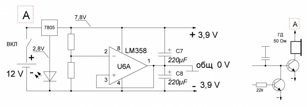
When I raised the gain in the RX path of the MD, it began to work unstably at maximum sensitivity, this was manifested in the fact that after passing over the target and detecting it, a signal was issued, but it continued even after there was no target in front of the search coil, this manifested itself in the form of intermittent and fluctuating sound signals. Using an oscilloscope, the reason for this was discovered: when the speaker is operating and the supply voltage drops slightly, “zero” goes away and the MD circuit goes into a self-oscillating mode, which can only be exited by coarsening the sound signal threshold. This didn’t suit me, so I installed a KR142EN5A + super bright white LED for power supply to raise the voltage at the output of the integrated stabilizer; I didn’t have a stabilizer for a higher voltage. This LED can even be used to illuminate the search coil. I connected the speaker to the stabilizer, after that the MD immediately became very obedient, everything started working as it should. I think the Volksturm is truly the best homemade metal detector!
Recently, this modification scheme was proposed, which would turn the Volksturm S into the Volksturm SS + GEB. Now the device will have a good discriminator as well as metal selectivity and ground detuning; the device is soldered on a separate board and connected instead of capacitors C5 and C4. The revision scheme is also in the archive. Special thanks for the information on assembling and setting up the metal detector to everyone who took part in the discussion and modernization of the circuit; Elektrodych, fez, xxx, slavake, ew2bw, redkii and other fellow radio amateurs especially helped in preparing the material.