How to light an ldc with burnt out threads. How to start DRL lamps with and without a choke? How does a fluorescent lamp work?
The so-called “daylight” lamps (LDL) are certainly more economical than conventional incandescent lamps, and they are also much more durable. But, unfortunately, they have the same “Achilles heel” - the filament. It is the heating coils that most often fail during operation - they simply burn out. And the lamp has to be thrown away, inevitably polluting the environment with harmful mercury. But not everyone knows that such lamps are still quite suitable for further work.
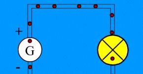
In order for the LDS, in which only one filament has burned out, to continue to work, it is enough to simply bridge those pin terminals of the lamp that are connected to the burnt-out filament. It is easy to determine which thread is burnt out and which is intact using an ordinary ohmmeter or tester: a burnt-out thread will show an infinitely high resistance on the ohmmeter, but if the thread is intact, the resistance will be close to zero. In order not to bother with soldering, several layers of foil paper (from a tea wrapper, milk bag or cigarette package) are strung onto the pins coming from the burnt-out thread, and then the entire “layer cake” is carefully trimmed with scissors to the diameter of the lamp base. Then the LDS connection diagram will be as shown in Fig. 1. Here, the EL1 fluorescent lamp has only one (left according to the diagram) whole filament, while the second (right) is short-circuited with our improvised jumper. Other elements of the fluorescent lamp fittings - such as inductor L1, neon starter EK1 (with bimetallic contacts), as well as interference suppression capacitor SZ (with a rated voltage of at least 400 V) may remain the same. True, the ignition time of the LDS with such a modified scheme can increase to 2...3 seconds.
A simple circuit for switching on an LDS with one burnt-out filament
The lamp works in such a situation like this. As soon as the mains voltage of 220 V is applied to it, the neon lamp of the EK1 starter lights up, causing its bimetallic contacts to heat up, as a result of which they eventually close the circuit, connecting the inductor L1 - through the whole filament to the network. Now this remaining thread heats up the mercury vapor located in the glass flask of the LDS. But soon the bimetallic contacts of the lamp cool down (due to the extinguishing of the neon) so much that they open. Due to this, a high-voltage pulse is formed at the inductor (due to the self-induction emf of this inductor). It is he who is able to “set fire” to the lamp, in other words, ionize mercury vapor. It is the ionized gas that causes the glow of the powder phosphor, with which the flask is coated from the inside along its entire length.
But what if both filaments in the LDS burn out? Of course, it is permissible to bridge the second filament. However, the ionization ability of a lamp without forced heating is significantly lower, and therefore a high-voltage pulse here will require a larger amplitude (up to 1000 V or more).
To reduce the plasma “ignition” voltage, auxiliary electrodes can be arranged outside the glass flask, as if in addition to the two existing ones. They can be in the form of a ring band glued to the flask with BF-2, K-88, “Moment” glue, etc. A belt about 50 mm wide is cut out of copper foil. A thin wire is soldered to it with PIC solder, electrically connected to the electrode of the opposite end of the LDS tube. Naturally, the conductive belt is covered on top with several layers of PVC electrical tape, “adhesive tape” or medical adhesive tape. A diagram of such a modification is shown in Fig. 2. It is interesting that here (as in the usual case, i.e. with intact filaments) it is not at all necessary to use a starter. So, the closing (normally open) button SB1 is used to turn on the lamp EL1, and the opening (normally closed) button SB2 is used to turn off the LDS. Both of them can be of the KZ, KPZ, KN type, miniature MPK1-1 or KM1-1, etc.

Connection diagram for LDS with additional electrodes
In order not to bother yourself with winding conductive belts, which are not very attractive in appearance, assemble a voltage quadrupler (Fig. 3). It will allow you to forget once and for all about the problem of burning out unreliable filaments.

A simple circuit for switching on an LDS with two burnt-out filaments using a voltage quadrupler
The quadrifier contains two conventional voltage doubling rectifiers. So, for example, the first of them is assembled on capacitors C1, C4 and diodes VD1, VD3. Thanks to the action of this rectifier, a constant voltage of about 560V is formed on the capacitor SZ (since 2.55 * 220 V = 560 V). A voltage of the same magnitude appears on capacitor C4, so a voltage of the order of 1120 V appears on both capacitors SZ and C4, which is quite sufficient to ionize mercury vapor inside the LDS EL1. But as soon as ionization begins, the voltage on capacitors SZ, C4 decreases from 1120 to 100...120 V, and on the current-limiting resistor R1 drops to approximately 25...27 V.
It is important that paper (or even electrolytic oxide) capacitors C1 and C2 must be designed for a rated (operating) voltage of at least 400 V, and mica capacitors SZ and C4 - 750 V or more. It is best to replace the powerful current-limiting resistor R1 with a 127-volt incandescent light bulb. The resistance of resistor R1, its dissipation power, as well as suitable 127-volt lamps (they should be connected in parallel) are indicated in the table. Here you can also find data on the recommended diodes VD1-VD4 and the capacitance of capacitors C1-C4 for LDS of the required power.
If you use a 127-volt lamp instead of the very hot resistor R1, its filament will barely glow - the heating temperature of the filament (at a voltage of 26 V) does not even reach 300ºC (dark brown incandescent color, indistinguishable to the eye even in complete darkness). Because of this, 127-volt lamps here can last almost forever. They can only be damaged purely mechanically, say, by accidentally breaking a glass flask or “shaking off” a thin hair of a spiral. 220-volt lamps would heat up even less, but their power would have to be excessively high. The fact is that it should exceed the power of the LDS by approximately 8 times!
Fluorescent tubular lamps have long been popular in lighting rooms of any size. They work for a long time and do not burn out, which means they require much less maintenance. The main problem is not the burnout of the light bulb itself (burnout of the filament and phosphor), but the failure of the ballasts. In this article we will tell you how to connect a fluorescent lamp without a choke and starter, and also power it from a low-voltage DC source.
Classic scheme for switching on fluorescent lamps
Despite technical progress and all the advantages of electronic ballasts (EPG), to this day a switching circuit with a throttle and starter is often found. Let's remember what it looks like:
A fluorescent lamp is a bulb, which is structurally designed as a straight and twisted tube filled with mercury vapor. At its ends there are electrodes, for example, spirals or needles (for products with a cold cathode, which are used in monitor backlighting). The spirals have two terminals to which power is supplied, and the walls of the bulb are covered with layers of phosphor.
The operating principle of the standard connection diagram for a fluorescent tube with a throttle and starter is quite simple. At the first moment of time, when the starter contacts are cold and open, a glow discharge appears between them, it heats the contacts and they close, after which the current flows through the following circuit:
Phase-throttle-spiral-starter-second spiral-zero.
At this moment, under the influence of the flowing current, the spirals heat up, while the starter contacts cool down. At a certain point in time, the contacts bend from heating and the circuit breaks. After which, due to the energy accumulated in the inductor, a voltage surge occurs and a glow discharge occurs in the lamp.
Such a light source cannot operate directly from a 220V network, because for it to work it is necessary to create conditions with the “correct” power supply. Let's consider several options.
Power supply from 220V without choke and starter
The fact is that starters periodically fail, and chokes burn out. All this is not cheap, so there are several schemes for connecting a lamp without these elements. You can see one of them in the picture below.

You can choose any diodes with a reverse voltage of at least 1000V and a current not less than the lamp consumes (from 0.5 A). Choose capacitors with the same voltage of 1000V and a capacity of 1-2 µF. Please note that in this connection circuit the lamp terminals are closed to each other. This means that the coils are not involved in the ignition process and the circuit can be used to ignite lamps where they have burned out.
This scheme can be used to illuminate utility rooms and corridors. You can use it in the garage if you do not work on machines there. The light output may be lower than with a classic connection, and the light output will flicker, although this is not always noticeable to the human eye. But such lighting can cause a stroboscopic effect - where rotating parts may appear to be stationary. Accordingly, this can lead to accidents.
Note: During experiments, keep in mind that launching fluorescent light sources in the cold season is always difficult.
The video below clearly shows how to start a fluorescent lamp using diodes and capacitors:
There is another diagram for connecting a fluorescent lamp without a starter and choke. An incandescent light bulb is used as ballast.

Use an incandescent lamp at 40-60 W, as shown in the photo:

An alternative to the described methods is to use a board from energy-saving lamps. In fact, this is the same electronic ballast that is used with tubular analogues, but in a miniature format.


The video below clearly shows how to connect a fluorescent lamp through an energy-saving lamp board:
Power supply of lamps from 12V
But homemade lovers often ask the question “How to light a fluorescent lamp from low voltage?” We have found one of the answers to this question. To connect a fluorescent tube to a low-voltage DC source, for example, a 12V battery, you need to assemble a step-up converter. The simplest option is a self-oscillator converter circuit with 1 transistor. In addition to the transistor, we will need to wind a three-winding transformer on a ferrite ring or rod.

This circuit can be used to connect fluorescent lamps to the vehicle’s on-board network. It also does not require a throttle or starter to operate. Moreover, it will work even if its coils are burned out. Perhaps you will like one of the variations of the considered scheme.


Starting a fluorescent lamp without a choke and starter can be done according to several considered schemes. This is not an ideal solution, but rather a way out of the situation. A lamp with such a connection diagram should not be used as the main lighting for workplaces, but it is acceptable for lighting rooms where people do not spend a lot of time - corridors, storage rooms, etc.
You probably don't know:
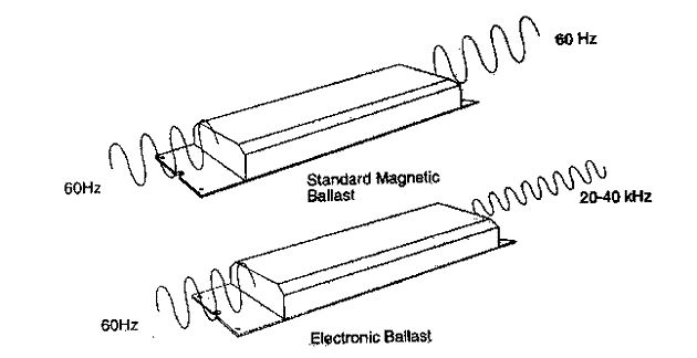
I have already said more than once that many things that surround us could have been realized much earlier, but for some reason they entered our everyday life quite recently. We have all encountered fluorescent lamps - those white tubes with two pins at the ends. Remember how they used to turn on? You press a key, the lamp begins to blink and finally enters its normal mode. This was really annoying, so they didn’t install such things at home. They were installed in public places, in production, in offices, in factory workshops - they are really economical compared to conventional incandescent lamps. But they blinked at a frequency of 100 times per second, and many people noticed this blinking, which was even more annoying. Well, to start each lamp there was a ballast choke, like a piece of iron weighing about a kilogram. If it was not assembled well enough, it would buzz rather disgustingly, also at a frequency of 100 hertz. What if there are dozens of such lamps in the room where you work? Or hundreds? And all these dozens turn on and off in phase 100 times per second and the throttles hum, although not all of them. Did it really have no effect?
But, in our time, we can say that the era of buzzing chokes and blinking lamps (both at start and during operation) is over. Now they turn on immediately and to the human eye their operation looks completely static. The reason is that instead of heavy chokes and periodically sticking starters, electronic ballasts (electronic ballasts) came into use. Small and light. However, just looking at their electrical diagram, the question arises: what prevented their mass production back in the late 70s and early 80s? After all, the entire element base was already there then. Actually, in addition to two high-voltage transistors, it uses the simplest parts, literally of a pittance cost, which were available in the 40s. Well, okay, the USSR, here production responded poorly to technological progress (for example, tube TVs were discontinued only in the late 80s), but in the West?
So, in order...
The standard circuit for switching on a fluorescent lamp was, like almost everything in the twentieth century, invented by the Americans on the eve of the Second World War and included, in addition to the lamp, the choke and starter we have already mentioned. Yes, a capacitor was also hung parallel to the network to compensate for the phase shift introduced by the inductor or, in even simpler terms, to correct the power factor.
Chokes and starters
 |
The principle of operation of the entire system is quite tricky. At the moment the power button is closed, a weak current begins to flow through the circuit network-button-throttle-first spiral-starter-second spiral-mains - approximately 40-50 mA. Weak because at the initial moment the resistance of the gap between the starter contacts is quite large. However, this weak current causes ionization of the gas between the contacts and begins to increase sharply. This causes the starter electrodes to heat up, and since one of them is bimetallic, that is, it consists of two metals with different dependences of changes in geometric parameters on temperature (different coefficients of thermal expansion - CTE), when heated, the bimetal plate bends towards the metal with a lower CTE and closes with another electrode. The current in the circuit increases sharply (up to 500-600 mA), but still its growth rate and final value are limited by the inductance of the inductor; inductance itself is the property of preventing the instantaneous inductance of current. Therefore, the choke in this circuit is officially called a “ballast control device”. This high current heats up the coils of the lamp, which begin to emit electrons and heat the gas mixture inside the cylinder. The lamp itself is filled with argon and mercury vapor - this is an important condition for the occurrence of a stable discharge. It goes without saying that when the contacts in the starter close, the discharge in it stops. The entire process described actually takes a fraction of a second.
| |
Now the fun begins. The cooled contacts of the starter open. But the inductor has already stored energy equal to half the product of its inductance and the square of the current. It cannot instantly disappear (see above about inductance), and therefore causes the appearance of a self-induction EMF in the inductor (in other words, a voltage pulse of approximately 800-1000 volts for a 36-watt lamp 120 cm long). Added to the amplitude mains voltage (310 V), it creates a voltage on the electrodes of the lamp sufficient for breakdown - that is, for a discharge to occur. The discharge in the lamp creates an ultraviolet glow of mercury vapor, which in turn affects the phosphor and makes it glow in the visible spectrum. At the same time, let us remind you once again that the choke, having an inductive reactance, prevents an unlimited increase in the current in the lamp, which would lead to its destruction or tripping of the circuit breaker in your home or other place where similar lamps are used. Note that the lamp does not always light up the first time; sometimes it takes several attempts for it to enter a stable glow mode, that is, the processes that we described are repeated 4-5-6 times. Which is really quite unpleasant. After the lamp has entered the glow mode, its resistance becomes significantly less than the resistance of the starter, so it can be pulled out, the lamp will continue to glow. Well, also, if you disassemble the starter, you will see that a capacitor is connected in parallel to its terminals. It is needed to reduce radio interference generated by contact.
So, very briefly and without delving into the theory, let’s say that a fluorescent lamp is turned on with a high voltage, and is kept in a luminous state by much less (for example, it turns on at 900 volts, glows at 150). That is, any device for switching on a fluorescent lamp is a device that creates a high switch-on voltage at its ends, and after the lamp is ignited, it reduces it to a certain operating value.
This American switching scheme was actually the only one, and only 10 years ago its monopoly began to rapidly collapse - Electronic ballasts (EPG) entered the market en masse. They made it possible not only to replace heavy buzzing chokes, to ensure instantaneous switching on of the lamp, but also to introduce a lot of other useful things such as:
- soft start of the llama - pre-heating of the coils, which dramatically increases the life of the lamp
— overcoming flicker (lamp power frequency is significantly higher than 50 Hz)
— Wide input voltage range 100…250 V;
— reduction in energy consumption (up to 30%) with a constant luminous flux;
— increase in the average service life of lamps (by 50%);
— protection against power surges;
— ensure the absence of electromagnetic interference;
- O no switching current surges (important when many lamps turn on simultaneously)
— automatic shutdown of defective lamps (this is important, devices are often afraid of idling)
— Efficiency of high-quality electronic ballasts — up to 97%
— lamp brightness control
But! All these goodies are sold only in expensive electronic ballasts. And in general, not everything is so rosy. More precisely, maybe everything would be cloudless if the EPR circuits were made truly reliable. After all, it seems obvious that electronic ballast (EPG) should in any case be no less reliable than a choke, especially if it costs 2-3 times more. In the “former” circuit consisting of a choke, a starter and the lamp itself, it was the choke (starter control element) that was the most reliable and, in general, with high-quality assembly could work almost forever. Soviet chokes from the 60s still work, they are large and wound with a fairly thick wire. Imported chokes with similar parameters, even from well-known companies such as Philips, do not work as reliably. Why? The very thin wire with which they are wound raises suspicion. Well, the core itself is much smaller in volume than the first Soviet chokes, which is why these chokes get very hot, which probably also affects reliability.
Yes, so, as it seems to me, electronic ballasts, at least cheap ones - that is, costing up to 5-7 dollars apiece (which is higher than that of a throttle), are made deliberately unreliable. No, they can work for years and may even work forever, but it’s like in a lottery - the probability of losing is much higher than winning. Expensive electronic ballasts are made to be conditionally reliable. We will tell you why “conditionally” a little later. Let's start our little review with the cheap ones. As for me, they make up 95% of purchased ballasts. Or maybe almost 100%.
Let's consider several such schemes. By the way, all “cheap” circuits are almost identical in design, although there are nuances.
 |
Cheap electronic ballasts (EPG). 95% of sales.
These types of ballasts cost 3-5-7 dollars and simply turn on the lamp. This is their only function. They don't have any other useful bells and whistles. I drew a couple of diagrams to explain how this newfangled miracle works, although as we said above, the principle of operation is the same as in the “classic” throttle version - we ignite with a high voltage, keep it low. It's just implemented differently.
 |
All the circuits of electronic ballasts (EPG) that I held in my hands - both cheap and expensive - were half-bridges - only the control options and the “piping” differed. So, an alternating voltage of 220 volts is rectified by the diode bridge VD4-VD7 and smoothed out by capacitor C1. In the input filters of cheap electronic ballasts, due to saving price and space, small capacitors are used, on which the magnitude of voltage ripple with a frequency of 100 Hz depends, despite the fact that the calculation is approximately as follows: 1 watt of lamp - 1 µF of filter capacitance. In this circuit there are 5.6 uF per 18 watts, that is, clearly less than necessary. This is why (although not only this), by the way, the lamp glows visually dimmer than from an expensive ballast of the same power.
Then, through the high-resistance resistor R1 (1.6 MOhm), capacitor C4 begins to charge. When the voltage on it exceeds the operating threshold of the bidirectional dinistor CD1 (approximately 30 volts), it breaks through and a voltage pulse appears at the base of transistor T2. Opening the transistor starts the operation of a half-bridge self-oscillator formed by transistors T1 and T2 and transformer TR1 with control windings connected in antiphase. Typically these windings contain 2 turns, and the output winding contains 8-10 turns of wire.
Diodes VD2-VD3 dampen negative emissions occurring on the windings of the control transformer.
So, the generator starts at a frequency close to the resonant frequency of the series circuit formed by capacitors C2, C3 and inductor C1. This frequency may be equal to 45-50 kHz, in any case, I was unable to measure it more accurately; I did not have a storage oscilloscope at hand. Please note that the capacitance of capacitor C3 connected between the electrodes of the lamp is approximately 8 times less than the capacitance of capacitor C2, therefore, the voltage surge across it is the same times higher (since the capacitance is 8 times greater - the higher the frequency, the greater the capacitance on a smaller capacity). That is why the voltage of such a capacitor is always chosen to be at least 1000 volts. At the same time, a current flows through the same circuit, heating the electrodes. When the voltage on capacitor C3 reaches a certain value, breakdown occurs and the lamp lights up. After ignition, its resistance becomes significantly less than the resistance of capacitor C3 and it does not have any effect on further operation. The generator frequency also decreases. Choke L1, as in the case of the “classic” choke, now performs the function of limiting the current, but since the lamp operates at a high frequency (25-30 kHz), its dimensions are many times smaller.
Appearance of ballast. It can be seen that some elements are not soldered into the board. For example, where I soldered a current-limiting resistor after the repair, there is a wire jumper.
One more product. Unknown manufacturer. Here they did not sacrifice 2 diodes to make an “artificial zero”.
 |

|
"Sevastopol scheme"
There is an opinion that no one will do it cheaper than the Chinese. I was sure of it too. I am sure until I got my hands on electronic ballasts from a certain “Sevastopol plant” - at least the person who sold them said so. They were designed for a 58 W lamp, that is, 150 cm in length. No, I won’t say that they didn’t work or worked worse than the Chinese ones. They worked. The lamps glowed from them. But…
Even the cheapest Chinese ballasts (electronic ballasts) consist of a plastic case, a board with holes, a mask on the board on the printed circuit side, and a designation indicating which part is which on the mounting side. The “Sevastopol version” was devoid of all these redundancies. There, the board was also the cover of the case, there were no holes in the board (for this reason), there were no masks, no markings, the parts were placed on the side of the printed conductors and everything that could be made of SMD elements, which I never I haven’t seen it even in the cheapest Chinese devices. Well, the scheme itself! I've watched a lot of them, but I've never seen anything like it. No, everything seems to be like the Chinese: an ordinary half-bridge. It’s just that the purpose of elements D2-D7 and the strange connection of the base winding of the lower transistor is completely unclear to me. And further! The creators of this miracle device combined a half-bridge generator transformer with a choke! They simply wound the windings on an W-shaped core. No one has thought of this, not even the Chinese. In general, this scheme was designed either by geniuses or alternatively gifted people. On the other hand, if they are so ingenious, why not sacrifice a couple of cents to introduce a current-limiting resistor to prevent current surge through the filter capacitor? Yes, and for a varistor for smooth heating of the electrodes (also cents) - they could go broke.
IN THE USSR
The above “American circuit” (choke + starter + fluorescent lamp) operates from an alternating current network with a frequency of 50 hertz. What if the current is constant? Well, for example, the lamp must be powered from batteries. Here you won’t be able to get by with the electromechanical option. You need to “make a diagram.” Electronic. And there were such schemes, for example, on trains. We all traveled in Soviet carriages of varying degrees of comfort and saw these fluorescent tubes there. But they were powered by a direct current of 80 volts, the voltage produced by the carriage battery. For power supply, “that same” circuit was developed - a half-bridge generator with a series resonant circuit, and to prevent current surges through the spirals of the lamps, a direct heating thermistor TRP-27 with a positive temperature coefficient of resistance was introduced. The circuit, it must be said, was exceptionally reliable, and in order to convert it into ballast for an AC network and use it in everyday life, it was necessary to essentially add a diode bridge, a smoothing capacitor and slightly recalculate the parameters of some parts and the transformer. The only "but". Such a thing would be quite expensive. I think its cost would be no less than 60-70 Soviet rubles, with the cost of the throttle being 3 rubles. Mainly due to the high cost of powerful high-voltage transistors in the USSR. And this circuit also produced a rather unpleasant high-frequency squeak, not always, but sometimes it could be heard; perhaps, over time, the parameters of the elements changed (the capacitors dried out) and the frequency of the generator decreased.
Power supply diagram for fluorescent lamps in trains in good resolution
 |
Expensive electronic ballasts (EPG)
An example of a simple “expensive” ballast is a product from TOUVE. It worked in the aquarium lighting system; in other words, it powered two green llamas of 36 watts each. The owner of the ballast told me that this thing is something special, specially designed for lighting aquariums and terrariums. "Eco-friendly". I still don’t understand what is environmentally friendly; another thing is that this “ecological ballast” did not work. Opening and analyzing the circuit showed that, compared to cheap ones, it is significantly more complicated, although the principle - half-bridge + triggering through the same DB3 dinistor + series resonant circuit - is retained in full. Since there are two lamps, we see two resonant circuits T4C22C2 and T3C23C5. The cold coils of the lamps are protected from surge current by thermistors PTS1, PTS2.
Rule! If you buy an economical lamp or an electronic ballast, check how this same lamp turns on. If it’s instant, the ballast is cheap, no matter what they tell you about it. In more or less normal conditions, the lamp should turn on after pressing the button in about 0.5 seconds.
Further. The RV input varistor protects the power filter capacitors from surge current. The circuit is equipped with a power filter (circled in red) - it prevents high-frequency interference from entering the network. The Power Factor Correction is outlined in green, but in this circuit it is assembled using passive elements, which distinguishes it from the most expensive and sophisticated ones, where the correction is controlled by a special microcircuit. We will talk about this important problem (power factor correction) in one of the following articles. Well, a protection unit has also been added in abnormal modes - in this case, generation is stopped by shorting the SCR base Q1 to ground with the SCR thyristor.
For example, deactivation of the electrodes or a violation of the tightness of the tube leads to the appearance of an “open circuit” (the lamp does not light up), which is accompanied by a significant increase in the voltage across the starting capacitor and an increase in the ballast current at the resonance frequency, limited only by the quality factor of the circuit. Long-term operation in this mode leads to damage to the ballast due to overheating of the transistors. In this case, the protection should work - the SCR thyristor closes the Q1 base to ground, stopping generation.
 |
It can be seen that this device is much larger in size than cheap ballasts, but after repair (one of the transistors flew out) and restoration, it turned out that these same transistors heat up, as it seemed to me, more than necessary, up to about 70 degrees. Why not install small radiators? I am not saying that the transistor failed due to overheating, but perhaps operation at elevated temperatures (in a closed case) was a provoking factor. In general, I installed small radiators, since there was room.
A fluorescent light bulb can be found in almost any room today. It is a source of daylight and makes it possible to save energy. Therefore, such lamps are also called housekeepers.
Appearance of a fluorescent lamp
But such products have one significant drawback - they burn out. And the reason for this is the combustion of the electronic filling - the throttle or starter. This article will tell you whether there is a way to connect fluorescent lamps without using a choke in the electrical circuit.
How does a housekeeper work?
The appearance of fluorescent lamps may vary. Despite this, they have the same operating principle, which is implemented thanks to the following elements that the device circuit usually contains:
- electrodes;
- phosphor - a special luminescent coating;
- glass flask with an inert gas and mercury vapor inside.

The structure of a fluorescent light bulb
This fluorescent lamp is a gas-discharge device with a sealed glass bulb. The gas mixture inside the flask is selected in such a way as to reduce the energy costs required to support the ionization process.
Note! For such lamps, in order to maintain the glow, you need to create a glow discharge.
To do this, a voltage of a specific value is applied to the electrodes of the fluorescent lamp. They are located on opposite sides of the glass flask. Each electrode has two contacts that connect to a current source. In this way, the space near the electrodes is heated.
The actual connection diagram for this light source consists of a series of sequential actions:
- heating of electrodes;
- then a high-voltage pulse is supplied to them;
- the optimal voltage is maintained in the electrical circuit to create a glow discharge.
As a result, an ultraviolet invisible glow is formed in the flask, which, passing through the phosphor, becomes visible to the human eye.
To maintain the voltage to create a glow discharge, the operating diagram of fluorescent lamps involves connecting the following devices:
- throttle. It acts as a ballast and is designed to limit the current flowing through the device to an optimal level;

Choke for fluorescent light bulbs
- starter. It is designed to protect the fluorescent lamp from overheating. At the same time, it regulates the intensity of the electrodes.
Very often, the cause of breakdown of the housekeepers is the failure of the electronic ballast filling or the burnout of the starter. To avoid this, you can avoid using burnt-out parts in the connection.

Standard connection diagram
The standard circuit used for connecting fluorescent lamps can be modified (go without a choke). This will minimize the risk of failure of the lighting fixture.

Switching option without ballast
As we found out, ballast plays an important role in the design of a fluorescent lamp. At the same time, today there is a scheme in which it is possible to avoid the inclusion of this element, which very often fails. You can avoid turning on both the ballast and the starter.
Pay attention! This connection method can also be used for burnt-out daylight tubes.
As you can see, this circuit does not contain a filament. In this case, the lamps/tubes will be powered through a diode bridge, which will create an increased DC voltage. But in such a situation, it is necessary to remember that with this method of power supply, the lighting product may darken on one side.
In implementation, the above scheme is quite simple. It can be implemented using old components. For this type of connection you can use the following elements:
- 18 W tube/light source;
- GBU 408 assembly. It will act as a diode bridge;

Diode bridge
- capacitors with an operating voltage not exceeding 1000 V, having a capacity of 2 and 3 nF.
Note! When using more powerful light sources, it is necessary to increase the capacitance of the capacitors used in the circuit.

Assembled circuit
It must be remembered that the selection of diodes for the diode bridge, as well as capacitors, must be carried out with a voltage reserve.
A lighting device assembled in this way will produce a glow slightly less bright than when using the standard connection option using a choke and starter.
What a non-standard connection option can achieve
Changing the usual method of connecting electrical components in fluorescent lamps is carried out in order to minimize the risk of device failure. Fluorescent lamps, despite having impressive advantages, such as excellent luminous flux and low energy consumption, also have some disadvantages. These should include:
- during their operation they produce a certain noise (hum), which is due to the functioning of the ballast element;
- high risk of starter burnout;
- possibility of filament overheating.
The above diagram for connecting the components of the electrical circuit will avoid all these disadvantages. When using it you will receive:
- a light bulb that will light up instantly;

What does the assembly look like?
- the device will operate silently;
- there is no starter, which burns out more often than other parts when the lighting system is used frequently;
- It becomes possible to use a lamp with a burnt-out filament.
Here the role of a choke will be performed by a regular incandescent light bulb. Therefore, in such a situation there is no need to use expensive and rather bulky ballast.
Another connection option
There is also a slightly different suitable scheme:

Another connection option
It also uses a standard light source with a power approximately equal to a fluorescent lamp. In this case, the device itself must be connected to the power supply via a rectifier. It is assembled according to the classical scheme, used to double the voltage: VD1, VD2, C1 and C2.
This connection option occurs as follows:
- at the moment of switching on, there is no discharge inside the glass bulb;
- then double the network voltage drops on it. Thanks to this, the light is ignited;
- the device is activated without preheating the cathodes;
- after starting the electrical circuit, the current-limiting lamp (HL1) is turned on;
- at the same time, HL2 establishes the operating voltage and current. As a result, the incandescent lamp will barely glow.
To make the start reliable, you need to connect the phase output of the network to the current-limiting lamp HL1.
In addition to this method, you can use other variations of the standard switching circuit.
Conclusion
Using modifications to the usual method of connecting fluorescent lamps, it is possible to exclude an element such as a choke from the electrical circuit. In this case, it is possible to minimize the negative effects (for example, noise) that are observed when operating a standard lighting installation of this type.
 Choosing a box for LED strips, correct installation
Dear visitors!!!
This method of connecting a fluorescent lamp should be familiar to everyone, in particular to professional electricians. With such a scheme for switching on a fluorescent lamp, there is one characteristic feature of the method of such connection, which you will have to familiarize yourself with. The information presented in this topic takes place in training students in the profession of “Electrician of electrical networks and electrical equipment,” which I am currently teaching.
How to turn on a fluorescent lamp - without a choke
The figure shows two ways to connect fluorescent lamps:
schematic diagram for switching on a fluorescent lamp with starter ignition (Fig. 1, a) and switching on a fluorescent lamp without a choke (Fig. 1, b).

For both schemes for switching on fluorescent lamps, the increased voltage pulse that promotes the formation of an arc discharge in the lamps (necessary for their ignition) is the inductor LL and the incandescent lamp EL2.
The second diagram (Fig. 1, b) shows a circuit for switching on a fluorescent lamp using an incandescent lamp (instead of a choke). In this circuit there is a current-carrying wire, one end of which is connected to one of the terminals of the electrodes of the fluorescent lamp. Instead of a live wire, you can use a wide strip of foil, which has the same electrical connection as the wire. Accordingly, both the piece of wire itself and the strip of foil must be secured at the ends of the bulb with metal clamps corresponding to the diameter of the bulb (fluorescent lamp).
That's all for now. Follow the section.