Installation of wall and hanging gutters. Wall-mounted and suspended gutters, what is the difference Installing a wall-mounted gutter
For the installation of a wall gutter on the mounted cornice overhang, the previously applied inclined lines (see Fig. 88) are restored on both sides of the watershed. Beacon hooks are installed on these lines near the “funnel” and on the watershed; their vertical bends should be on the indicated lines. Between the beacons (perpendicular to the lines) the rest of the hooks are attached in the same way at intervals of 670-730 mm. The hook on the watershed is set perpendicular to the cornice overhang.
The prepared pictures of the gutters are collected, as well as the cornice covering. When making paintings, the direction of water flow is taken into account. The assembly is carried out from the water intake funnels to the watershed. The sides of the gutter are overlapped with each other, taking into account the direction of water flow. At the same time, make sure that the upper edge of the paintings on the cornice is always located above the top of the gutter side. On the watershed and when joining at the funnel, the paintings are connected with a double lying seam. The sides of the gutters on the hooks are fixed with rivets. The upper longitudinal edge of the wall gutters is connected to the patterns of the ordinary coating with a seam seam. The tray is installed along the axis of the water intake area in such a way that its tail lapel is under the ends of the connected wall gutters.
Rice. 89. Wall gutter device:
1 - a pin with a bracket, 2 - a water intake funnel, 3 - a tray, 4 - a groove flooring, 5 - a rafter leg, 6 - a cornice flooring, 7 - purlin, 8 - picture of the wall gutter, 9, 13 - nails, 10 - crutch, 11 - hook for the gutter, 12 - picture of the cornice overhang , 14 - klyamery
The lapel is fastened with four nails measuring 30X40 mm. The sides of the trays and gutters are connected with corner folds that are bent onto the inner planes of the tray sides (Fig. 89, node 2).
Trays for water intake funnels, assembled in the corners of the roof of a building, are somewhat different from conventional trays installed on its eaves. If trays for cornices can be prepared in advance, then corner trays are usually made on the spot according to full-scale measurements. At the same time, the width of the pictures of wall gutters, their position relative to the cornices and the height of the sides are taken into account.
Suspended gutters are semi-circular or rectangular trays that are hung directly under the draining edge of the eaves. Hanging gutters serve the same purposes as wall gutters. The water collected by the gutters is diverted to the funnels.
On the eaves, the gutter is positioned so that the water flowing from the slope does not overflow through its front side.
Before installing the tray brackets, the horizontality of the leading edge is checked by level. Staples are attached in this sequence. First, two extreme (lighthouse) brackets are installed, a cord is pulled between them and the rest of the brackets are marked and cut into the plank base.
The gutter raised on the cornice (Fig. 90) is laid on tray brackets 2 and fastened with cleats 6. To avoid the consequences of the expansion of the gutter during temperature fluctuations, compensators are arranged in it or movable seams are made.
The compensator is a water intake funnel, which includes freely laid ends of hanging gutters on both sides. This design of the gutter allows it to freely lengthen or shorten by 10-15 mm, which is quite enough for temperature changes at different times of the year.
A movable seam is made at the point of the highest rise of the gutters. Here, the end ends of the gutters are sealed with tin plugs. A temperature gap of 30-40 mm is left between their ends. Both ends of the gutters are closed on top with a tin lid (two slopes), through which water flows down to the ends of the gutters. In some cases, you can limit yourself to rigid fastening of the gutter to one of the brackets located in its middle, leaving the ends only movably fixed in the cleats.
Rice. 90. Hanging chute device:
a, b. c - options for arranging gutters (villages are given at the points of the highest rise); 1 - gutter, 2 - tray bracket, 3 - roofing, 4 - flooring, 5 - rivet, b - cleat, 7 - screw with a sunk head, 8 - picture of the cornice overhang, 9 - nail, 10 - spacer
The device of water intake funnels. Water intake funnels are made in a round or rectangular shape. In both cases, one or two holes are arranged in them for the entry of gutters. The funnel is attached to the eaves with a standard pin with a crimp collar. It is recommended to additionally fasten the lapels of the funnel rim with rivets to both sides of the tray. After that, the pictures of the cornice overhangs are laid (if they are provided) and proceed to the coating.
Roof drainage: internal or external
When snow melts and especially during heavy rains, the problem of draining water from the roof will arise as sharply as possible, since its excess will sooner or later lead to a violation of the integrity of the house structure, up to the foundation. There is no shortage of ready-made systems of this kind on the modern market. In order for them to function effectively, it is enough just to connect the elements together correctly.
Types of drainage systems
The drainage system from the roof is internal and external. The choice of the system is based on such parameters as the temperature regime of the premises, the profile and design of the coating, the length of the slopes and the amount of precipitation in the construction region.
Internal drainage from the roof involves the location of pipes inside the building, as a rule, at some distance from the walls. It consists of water intake funnels, outlet pipes, risers and outlet. If it is correctly installed, it will work effectively both at a positive external temperature and a negative one. Internal drainage is considered the most reliable option for removing water from roofs, since a positive temperature in a heated building virtually eliminates the risk of water freezing in risers. Most often, water is drained from such a system into an external sewerage network, rainwater or common alloy.

External drainage from the roof, in turn, is divided into:
- unorganized - in these systems, water is drained along the overhangs of the eaves;
- organized - provides the discharge of flowing water through the gutters to the external drainpipes.
The first option has a number of disadvantages, due to which they are provided quite rarely. In particular, with such an organization of water flow, the walls can be moistened, which leads to a decrease in their thermal performance and durability, and the ice formed on the cornices causes the destruction of the roof. In the case of organized drainage, the disadvantages of this type appear to a much lesser extent, however, the water in the gutters and drain pipes should not freeze, otherwise the entire system will be in danger of failure. Therefore, if the installation of an anti-icing system for drains is not provided, an organized external drainage system is more suitable for those climatic zones where water in the external elements of the system will not freeze. Any external drainage system includes suspended and horizontal wall gutters, vertical drain pipes and drains, through which the vertical elements of the drain are connected to the horizontal ones.
The gutter is the most important element of the system

wall gutter
Although this element is called a wall element, in fact it is located at the very edge of the slope, very close to the cornice overhang. By design, these are low sides of 15–20 cm, which act as a water barrier. Trays are installed at an angle to the overhang so that two of them, converging at the lowest level, hang directly over the funnel of the drain pipe. When water drains from the roof, it hits the side and then rushes along the path of least resistance, that is, towards the funnel.
In conditions of very rare rains, the angle of inclination is insignificant - only a couple of millimeters per linear meter of the gutter. An angle of 15⁰ is considered optimal - with any amount of precipitation, they will not overflow through the barrier. In addition, such a design prevents the formation of icicles and landslide snow from the roof, which is undoubtedly an advantage. The fastening of one tray to another is carried out in different ways - with a double lying fold or with glue, depending on the material. The installation of wall gutters is started after covering the cornice overhangs.
Suspension
Unlike a wall-mounted one, a rain (suspended) gutter is fixed directly under the roof overhang and so tightly that the water from the roof that has gained some speed does not pour under the tray. On weight, it is usually held by special metal hooks, they are shaped to match the tray. Brackets, if they are extended beyond the upper edge of the wall, are attached to the rafters or to the frontal board, which is located under the overhang.
In the first case, the deflections of the brackets differ and increase as you approach the location of the downpipes, usually the corners of the building. When fastening to a windboard, fasteners are simply positioned at different levels to provide the required slope.
The angle of inclination of the gutter in the drainage system depends on the intensity of precipitation falling per year.
The gutter, generally speaking, should not be interrupted anywhere, even above the funnel. During installation, such a hole is cut in this place so that its throughput is enough to prevent water from accumulating at high pressure.
Gutter calculation
The usual length is three to four meters. Their required number is calculated based on the perimeter of the roof. Next, carry out the calculation of additional accessories:
- connectors - one for two trays;
- hooks - one for every 60 cm of its length;
- plugs - for each final design.
Construction assembly
Trays are connected by special elements, in the upper part of which there are grips. It is in them that the edges of the gutter are fixed. Corner joints are made through special elements under the outer and inner corner, that is, the gutters in these places can no longer be sawn and unnecessary joints can be avoided. In sections longer than 18 m, instead of a standard connection, an expansion joint is used, on both sides of which brackets are mounted for the drain.
Types of gutters: material and sectional shape

They may differ in cross-sectional shape. For instance,
- semicircular - universal, they can be used for any roof, and because of this they are the most popular. The special shape of the tray edges ensures the rigidity of the element and resistance to mechanical stress.
- semi-elliptical - due to their large throughput, they are excellent for large roof areas.
They are also distinguished by the material of manufacture. Let's look at some of the most common options.

Plastic. During production, they are coated with an acrylic or titanium dioxide layer that increases their resistance to weathering. Plastic, as a rule, is painted over in bulk, so small defects, say, scratches, which may appear on the surface of the product over time, are hardly noticeable. Installation of the drain is carried out by means of latches, couplings equipped with rubber gaskets, or gluing.
Steel. These are galvanized products coated with a polymer material that is resistant to corrosion, mechanical stress and fading. A wide color palette makes it easy to match the gutter to the color of the facade or roof. The connection is made using locks or staples equipped with latches with rubber gaskets. Installation is facilitated by brackets and holders having a snap-on design.
Aluminum. Usually they are varnished or painted in various colors and thus provide anti-corrosion protection. The elements of the system are connected by riveting, then the joints are sealed with silicone, special paste or glue for aluminum.
Drain system

It is clear that the water flowing from the roof eventually drains through the pipes, but how does it get there? Trays and pipes are connected to each other through a kind of adapter - a funnel. There are several design options for such a part:
- inclined with a neck located at an angle;
- adjustable inclined, the position of the neck can be changed arbitrarily;
- with extension functions, with the same functions as a similar connector.
From below, an ordinary pipe with an expander or an elbow is attached to its branch pipe, which can provide a turn of 45⁰, 60⁰ or 75⁰. The transition element can also consist of two elbows, each of them can be bent at the required angle.
 In the middle, the drain can be equipped with a tee for branching. The lower part of the drain can go into
- a simple drain that provides an orifice tip;
- collector, in this case, a nozzle with the same diameter as the point collector is mounted.
Features of installation of wall and hanging gutters in the drainage system
To protect the walls, the foundation of the house from rain or melt water, it is necessary to equip its roof with a water drainage system. If water from a pitched roof flows directly to the ground (the so-called unorganized drain), then over time, due to the high hydrostatic load, the basement and foundation may be destroyed, and the facade of the building may be damaged. Drainage systems collect water from the entire surface of the roof and send it to one specially designated place. The water drainage system consists of several elements, including downpipes, a wall-mounted or suspended gutter with fasteners, funnels for draining water. When choosing the elements of the drainage system, the aesthetic component should also be taken into account - its color and the materials from which the ebbs are made should be combined with the roof, windows, and platbands of the house.
Video instruction for installation of the drainage system
Organized external drainage
Outdoor organized drainage is suitable for use in those climatic zones where the water in the outer pipes will not freeze. When organizing such a water drainage system, the following points should be considered:
- Wall and hanging gutters can be mounted on roofs with a slope of at least 15 degrees;
- Installation of gutters should be carried out with a longitudinal slope of at least two degrees;
- When calculating the area of downpipes, it is assumed that one square meter of the roof should account for one and a half centimeters of the pipe section.
Let us dwell in more detail on the designs of gutters for water flow and consider their features, advantages and disadvantages.

wall gutter
The wall gutter is mounted on the edge of the roof slope near its overhang. The design is a low ledge, installed at a slight angle to the overhang so that the two gutters, converging at the lowest point, hang directly over the drainpipe funnel. Water, flowing down the roof, hits the wall of such a side and then goes directly into the pipe. The undoubted advantage of such a system is that it prevents the avalanche of snow from the roof and the formation of icicles.
The wall gutter is more durable than the hanging gutter and is more suitable for the harsh snowy Russian winters. Such designs are available both made of plastic and more durable metal. The material is selected depending on the material of the roof. So, a copper wall gutter is best suited to a copper roof - the photo below shows an example of a roof made of copper and a drainage system.
The disadvantage of wall structures is that in winter, ice and snow accumulating in them are saturated with melt water when the temperature rises, and leaks may occur.

Hanging chute
The suspended gutter is mounted under the roof overhang using special metal brackets that repeat their shape. Fasteners are mounted either to the rafters or to the frontal (wind) board, which is located under the overhang. During installation, it must be borne in mind that in the case of attachment to the rafters, the brackets must have a different deflection, the value of which will increase towards the corner of the house, where, as a rule, a downpipe is attached. If the installation is carried out to the frontal board, it is enough to install the fasteners at different levels, thereby providing the structure with the necessary slope. It is best not to interrupt the gutter above the drainpipe funnel, but to cut a hole in this place of such a diameter that water does not accumulate in it.
Suspended structures provide complete collection of all water from the roof, including drops from the eaves, which is their advantage. The disadvantages include susceptibility to deformation in the event of frost and icicles, in addition, snow and ice coming off the roof can tear the structure off the fasteners.

How to calculate the spillway system
The roof area is the main parameter on which the diameter of the elements of the weir system and the required number of funnels depend. When calculating, the following points should be taken into account:
- If the roof of the house does not exceed 70 sq. m., the diameter of the pipes should be 50-75 mm, and the gutters - 70-155 mm;
- For roofs over 100 sq. m., the diameter of the drain pipes is 75-100 mm, and the cross-section of the gutters is 115-130 mm.
- For roofs over 100 sq. m. gutters with a diameter of 140-200 mm and pipes of 90-160 mm are required.
In addition, it is necessary to correctly calculate the slope angle. A small slope can cause it to overflow with water, and a large angle can cause the funnel not to pass the right amount of water. During installation, the slope of the gutters is made at the rate of 2-4 mm per meter of its length.

A properly installed drainage system will help protect the walls and foundation of your home from damage caused by water intrusion. When calculating and installing a structure, a number of important points must be taken into account: choosing the right material for its constituent elements, determining the method of fastening and choosing the angle of inclination of the gutters, calculating the diameter of the pipes and the number of funnels, etc. Therefore, in order to be sure that your home is reliably equipped with a quality drainage system, it is best to entrust this work to professionals.
Wall and hanging gutters
Device diagram wall gutter in the outer corners of the house on the pitched rafter roof of the house is shown in Fig.1.
Scheme of the device of a wall gutter in the outer corners of the house on a pitched roof.
1- sparse roof lathing; 2- continuous flooring along the slope of the roof; 3- covering the roof overhang; 4- wall inclined chute; 5- onboard chute limiter; 6- chute holder; 7- drain from the gutter into the drain; 8- drain funnel; 9- downpipe; 10- covering the roof ribs; 11- roofing.
Coating of cornices and grooves should be made from roofing steel sheets connected one to another, as well as with a row covering, double lying seams, filling the seams with putty.
Mutual displacement of lying folds adjacent rows of paintings within one roof slope and the mutual displacement of standing seams on opposite roof slopes must be at least 50 mm.
Device diagram wall gutter in the inner corners of the house and a groove in the valleys pitched truss roof of the house is shown in Fig.2.
Scheme of the device of a wall gutter in the inner corners of the house and a groove in the valleys of a pitched roof.
1- sparse roof lathing; 2- roofing sheathing continuous along the slope of the roof; 3- covering the roof overhang; 4- wall inclined chute; 5- onboard chute limiter; 6- chute holder; 7 - drain tray from the gutter to the drain; 8- drain funnel; 9- downpipe; 10- coating of the valley roof; 11- roofing; 12 - roofing crutch.
The rolled vapor barrier carpet is conditionally not shown - for clarity of the coating option.
grooves(fig.2 pos.10) and overhangs(fig.2 pos.3) with wall gutters(Fig. 2 pos. 4) asbestos-cement and tile roofs in the absence of tray parts should be covered with galvanized sheet steel roofing.
At the junction with the groove(Fig. 2 pos. 10) roofing piece materials must go beyond the edge of the tray for at least 100 mm.
Trays for water intake funnels(Fig. 3 pos. 7), collected in the corners of the roof of the building, are somewhat different from conventional trays installed on its eaves.
If trays for cornices can be prepared in advance, then corner trays are made at the place of their installation by actual size. This takes into account the width of the paintings(fig.3 pos.4) wall gutters, their position relative to the cornices and side heights(fig.3 pos.5).
Device diagram wall gutter for any type of roof in the inner corners of the house pitched truss roof of the house is shown in Fig.3.
Scheme of a wall gutter for any type of roof in the inner corners of a pitched roof.
1- sparse roof lathing; 2- roofing sheathing continuous flooring along the roof slope; 3- covering the roof overhang; 4- wall inclined chute; 5- onboard chute limiter; 6- hook chute holder; 7 - drain tray from the gutter to the drain; 8- drain funnel; 9- downpipe; 10- roofing crutch; 11-clamp for attaching the gutter; 12- drip cover overhang; 13- nails.
The rolled vapor barrier carpet is conditionally not shown - for clarity of the coating option.
Overhangs paintings(Fig. 3 pos. 3) are fixed to a continuous crate (Fig. 3 pos. 2) with nails, with overlapped trough patterns(fig.3 pos.4), and to metal roofing crutches(fig.3 pos.12), nailed to the crate at a distance 700 mm one from the other.
Overhangs covering patterns(fig.3 pos.3) and grooves(Fig.2 pos.10) are attached to the crate using clamp(fig.3 pos.11) - at least two on one side of the sheet.
2. Preparation and fastening of a funnel for wall gutters.
Inlet funnels for hanging gutters make a round or rectangular shape. In both cases, they install one or two gutter entry holes v.
The shape of the pipes of the drainage system can be round or rectangular:
- funnels rectangular perform size - 300x250 mm;
- round funnels perform size - 260 mm or 320 mm.
2.1. Open funnels for drainpipes.
Funnel rim lapels(fig.4 pos.2) IT IS RECOMMENDED to additionally fasten with rivets to both tray sides(fig.4 pos.1).
Thereafter stack pictures(fig.3 pos.3) cornice layers (if any) and start covering the roof.
Funnel cutting option for downpipes d=110 mm and wall gutters shown in Fig.4.
The scheme of cutting the funnel for downpipes and wall gutters.
1- tray wall gutter; 2- restrictive rim of the overflow of the drain funnel; 3- cone of a drain funnel made of roofing steel with a thickness of 0.7 mm; 4- glass funnel; 5- side rim limiting the fastening of the part; 6 - lapels of the assembly of assembly parts, width 10 ... 12 mm; 7- drainpipe.
To perform a workpiece stencil intake cone funnels on thick paper draw its scan with allowances for the edges ( 10…15 mm) for folds according to the scheme (Fig. 4 pos. "a ... p").
Top edge limiter(Fig. 4 pos. 2) perform height 14…15 mm for rolling into the edge of the rim of the wire d=3…4mm.
On the cone blank(Fig. 4 pos. 3) bend roller edges(Fig. 4 pos. "d, f"). After that, the workpiece is rolled into a cone.
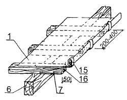
2.2. Installation of a funnel for wall gutters.
funnel(Fig. 5, pos. 1) the downpipe is connected with tray(Fig. 5, pos. 2) with recumbent folds, for which a cutout is made in the shell of the funnel with a width corresponding to the width of the tray.
Option to install a water intake funnel with wire mesh filter and gutter tray for wall gutters is shown in Fig.5.
How to install a funnel with a wire mesh filter and a drain tray for wall gutters.
1- water intake funnel d=260 (320) mm with a wire mesh filter; 2- drain tray; 3- wall chute; 4- ribs of the wall gutter; 5- hook for fastening the ribs of the gutter; 6- covering the roof overhang; 7- crutches for fastening the overhang cover; 8- wooden overhang flooring; 9- slate roofing.
The funnel is attached to the cornice standard pin with crimp collar.
Water intake installation option funnels for wall gutters on the overhang eaves the roof of the house is shown in Fig.6.
Scheme of fixing the water intake funnel for wall gutters on the eaves of the roof overhang.
1- water intake funnel d=260 mm; 2 - eaves drain tray; 3- edge of the wall gutter; 4- downpipe d=110 mm; 5- collar; 6 - cornice overhang shield made of boards 50 mm thick; 7-post fencing with fastening to the eaves shield with M 8x30 mm bolts and rubber gasket; 8- roof roof.
When choosing the shape and size of pipes and gutters it is necessary to take into account the slope, number and location of water flow points.
Scheme for calculating points of wastewater (funnel) an organized external drainage system on a roof with a drainage system is shown in Fig. 1 in the section of the site “Establishment and repair of drainage from pitched roofs of buildings. Arrangement of cornice overhangs of roofs for hanging gutters.
Gutter systems
Installation of wall gutters with a funnel.
Device diagram wall gutter with a funnel for a drain for any covering of a pitched truss roof of a house is shown in Fig. 7.
Scheme of the device of a wall gutter with a funnel for a drain for any coating on straight sections of a pitched roof.
1- pictures of overhangs; 2- wall gutter; 2a - wall gutter rib; 3- chute tray; 4- drain funnel; 5- collar under the funnel; 6- crutches for roof overhangs; 7- hooks for fastening the wall gutter; 8- plank flooring of the roof overhang; 9- clamp; 10- nail; 12- overhang drip.
Vertical seams of downpipes(Fig. 7, pos. 6) are performed with recumbent folds with a width of no more 10 mm with landing.
Gutter cutting option funnel tray wall gutters shown in Fig.8.
A variant of cutting a gutter tray for a funnel.
Gutter trays must have a slope of at least 15% and width 105…215 mm at the bottom and 160…226 mm at the top.
Consumption of materials for parts from roofing sheet steel 0.5 mm thick according to the meters indicated in table 1.
Table 1: Consumption of materials for parts made of roofing sheet steel with a thickness of 0.5 mm according to the meters indicated in the table.
Consumption of materials per 1 m2 of coating when changing wall gutters, cornice overhangs and grooves made of sheet steel is shown in Table 2
Table 2: Consumption of materials per 1 m2 of coating when changing wall gutters, cornice overhangs and grooves.
| p/n | Name of materials | Unit rev. | Roof parts | |||
| Wall gutters | Cornice overhangs with wall gutters | Grooving width | ||||
| 700 mm | 1400 mm | |||||
| 1 | 2 | 3 | 4 | 5 | 6 | 7 |
| 1 | Roofing sheet steel 4 kg | kg | 2,98 | 5,92 | 2,98 | 6,2 |
| 2 | Nails - 75 mm | kg | - | - | 0,017 | 0,018 |
| 3 | Nails - 50 mm | kg | 0,005 | 0,01 | - | - |
| 4 | Wire 3 mm | kg | 0,059 | 0,118 | - | - |
| 5 | Metal hooks 0.8 kg | kg | 1,17 | 1,17 | - | - |
| 6 | Crutches 2 kg | kg | - | 2,89 | - | - |
Installation of downpipes for wall gutters see in the site section “Installation of downpipes for external drainage gutters. Fixing drainpipes.
wall gutter
 When repairing roofs with a wall gutter, strict adherence to the set of rules for design and construction (SP 31-101-97) is necessary, installation in another way is not allowed. If violations are detected, then the contractor will definitely have problems with the “acceptance” of the work.
Our company manufactures a complete set of accessories for the correct installation of an organized drain with a wall gutter.
The components include:
- pictures of a wall gutter made of galvanized steel with a seam connection (lying seam), element 1;
- wall gutter tray with rebate connection, element 2;
- wall gutter hook, element 3;
- T-shaped crutch, element 4;
- funnel drainage (drainage funnel), element 5;
- drainpipe with fastening clamps.
The pictures and the tray of the wall trough are made on a Schechtl CNC bending machine, thanks to this, fast and high-quality bending is possible on an urgent basis. The thickness of the metal used is 0.43-0.7 mm.

Installation of a drainage system with a wall gutter. The photo shows a crate, a gutter with a tray for draining water, mounted seam paintings.
wall gutter
The picture of the wall gutter is a sheet of galvanized steel, on one side of which a shelf of 100 mm (A) is rolled and bent by 110 degrees (depending on the slope of the roof), on the other side a bend of 145 degrees is made by a value of 15-25 mm ( B). A recumbent fold (F) is formed from the ends of the product. During production, the product is formed in such a way that the horizontal surface of one picture at the junction fits into another picture, that is, the horizontal shelf (C) on the left and right has a different width.

Installation of a wall gutter during the repair of a folded roof. The photo shows the crate on which the pictures of the gutter are mounted.
Wall gutter tray
The wall gutter tray is structurally similar to the gutter itself, but the shelf (A) is not parallel to the bend (B) and creates a direction for the outflow of water to the center where the spout of the tray (H) is embedded. The tray spout has a length of about 200 mm (according to the customer's drawing) and has a tapered shape. The manufacture of the tray is somewhat more complicated and therefore requires more time.

In the photo, a wall gutter tray manufactured by our company is mounted and connected to the gutter directly on the roof.
Wall gutter hook
The wall gutter hook is made of strip 40*4 with subsequent painting, galvanizing is possible. The hook profile consists of two shelves, one 300-500 mm long with holes for self-tapping screws, the other 100 mm long bent at an angle of 110 degrees (depending on the roof slope, it may have a different slope).

The photo shows two types of hooks for mounting the wall gutter. Other options are possible, but these are the most commonly ordered.
T-crutch
Drainage systems.
The removal of rain and melt water from roofs is a necessary measure to ensure the normal operation of buildings. Methods of intake and release must be justified in the project, and drainage devices must comply with the requirements of GOSTs.
In the simplest version, water from a pitched roof can drain directly to the ground. This type of drainage is commonly referred to as disorganized. The justification for its use is limited to isolated cases: for example, for small buildings with a shed roof (and provided that water does not fall on the blind area or sidewalks). But it must be understood that unorganized drainage eventually leads to damage to the elements of the facade, destruction of the basement and premature wear of the foundation due to excessively high hydrostatic load.
There are only two ways organized drainage: internal and external. External drainage, in addition to the direct function of draining water, must have elements of aesthetics.
At internal drainage pipes are located inside the building, usually away from the outer walls. Roofing, valleys and grooves in this case should have slopes to the water intake funnels. Water intake funnels must be placed evenly over the roof area in low areas and at a distance of at least 500 mm from parapets and other protruding parts of the building. The roof area per one funnel should be set at the rate of 0.75 sq.m. roofing per 1 sq. cm of the cross section of the pipe.
With organized external drainage The water flowing down from the roof is channeled through the gutters to the external drainpipes. Such drainage is the most popular, but also more laborious, compared to unorganized. It is formed by a drainage system, completed from several elements. For temperate latitudes with an average amount of precipitation, an organized drainage system installed around the perimeter of the building is the best option. At the same time, it cannot be said that gutters and downpipes spoil the appearance of the building. On the contrary, tastefully selected, they give the house a certain completeness and enliven it, giving the house comfort and signs of being inhabited.
Any external drainage system consists of horizontal wall or hanging gutters, vertical downpipes and drains, through which the vertical elements of the drainage system are connected to the horizontal elements.
The main features that one has to face when arranging an external drainage system in our conditions:
- eaves, joints of slopes and gutters freeze over in winter. This problem is solved mainly through the use of special anti-icing systems, it is also important to pay special attention to the correct fastening of individual elements of the drain to each other;
- snow falling like an avalanche from the roof can sometimes tear off horizontal gutters-trays from the mounts. This problem can be solved if, instead of a wall gutter, a hanging tray is installed under the edge of the eaves. Moreover, the outer, open edge of the tray should not be above the conditional plane that continues the surface of the overlying slope, and the middle of the tray should be vertically right under the edge of the eaves drain so that all rainwater flows into the tray. On pitched roofs, it is desirable to install snow-retaining elements that prevent snow avalanches, which not only threaten the health of passers-by, but can also damage the drainage system;
- special attention should be paid to the methods of articulation of individual elements of the spillway system and the elimination of joint leaks;
- clogging of drains with falling leaves and branches requires the organization of easy access for their maintenance;
- a complex roof profile entails an increase in the length of the elements of the drainage systems, the complication of their profile, as well as an increase in the likelihood of errors during design and installation, which generally reduces the efficiency of the entire drainage system;
Above the entrances to buildings and above other places of pedestrian zones on pitched roofs, it is necessary to arrange snow retention.
The main parameters of the system calculation.
1.
The main parameter in calculating the capacity of the gutter system, its configuration is catchment area. Most often, the catchment area is taken as the area of the slope or the area of the projection of the slope onto a horizontal plane.
2.
Bandwidth gutters and pipes depends not only on their section, but also on the design of the system. For example, doubling the length of a gutter leads to a similar decrease in its throughput, since it is the length of the gutter that limits the amount of water flowing from the roof. It is necessary to choose the most suitable gutter in size, that is, to make a configuration from the smallest number of main and connecting elements and thus simplify installation, reduce the cost of the system as a whole. The sides of the gutters are made at least 120 mm high, and the distance between the drainpipes is no more than 24 m (usually 12 ... 14 m).
3.
Much attention is paid to the throughput of the gutters by their bias. With an insufficient slope (less than 2%), "overlapping" is possible, with a very large one, "flooding" of the receiving funnels.
4.
Wall or hanging gutters are installed on roofs, the coverings of which are made with a slope of more than 15%.
5.
The clear area of the drain pipe is taken at the rate of 1.5 cm2 of its cross section per 1 m2 of the roof area.
Main points of system installation.
Drainage system with hanging gutter.
1.
Picture of the cornice overhang.
2.
Hanging gutter.
3.
Hanging gutter with end cap.
4.
Groove with inset.
5.
Drainpipe. It is hung in two steps from the bottom up: first the grips, then the elements of the drain pipes (lower link, inter-knee, knee, funnel).
6.
T-bracket.
7.
The suspension bracket is selected in such a way that the pipes are spaced from the wall at a distance of 100-150 mm.
8.
Knee.
9.
The mark is mounted at a distance of 30-40 cm from the ground level.
Drainage system with wall gutter.

1.
Picture of the cornice overhang.
2.
Picture of a wall gutter. They are laid at the end of the coating of the cornice overhangs. Usually located between water intake funnels with a slope of 1:20 to 1:10.
3.
Water tray.
4.
Wall bracket. Work on the installation of the system begins with their installation. Put on top of cornice paintings.
5.
T-bracket.
6.
Bracket for connecting the tray with a water intake funnel.
Maintenance of the drainage system.
Elimination of minor defects and malfunctions.
Malfunctions of drainage devices, leading to waterlogging of house structures, must be eliminated immediately.
Downspouts and other details of black roofing steel are periodically, every 3 years, painted with oil paint.
Debris must not be allowed to accumulate in gutters, internal drainage funnels and downpipes. In the spring, after the snow melts, the roof is cleaned of debris, the surface of the protective layer of the roof is inspected, drains are cleaned, and damage is eliminated.
To clean the water intake funnels from dust, silt and dirt, the receiving grates and glasses are removed and cleaned. To prevent clogging of the inlet funnels of the internal drainage system, special protective caps must be installed above the inlet funnel.
Periodically check the tightness of the mating of the roofing carpet with the funnel, the serviceability of the compensation socket (to compensate for temperature and sedimentary deformations) located in the upper part of the drainpipe, the tightness of the connection in the individual sections of the riser, as well as the serviceability of the hydraulic shutter, revisions and cleanings. If the "compensator" is faulty, the roofing carpet is torn in its connections with the water intake funnel.
In order to avoid freezing of drain funnels and pipes, it is necessary to arrange thermal insulation of pipeline sections within the attic, technical underground (floor) and outlets.
Cleaning roofs from debris, snow and ice.
On all types of roofs of residential buildings during operation, it is required to clean the roofs and drainage devices from debris, which prevents the flow of water. It is necessary to clean the protective gratings, water intake funnels of both internal and external drains.
Roofs are swept as leaves accumulate on the roof. A prerequisite is the cleaning of roofs and gutters from debris in the fall before the snow falls and in the spring after the snow melts.
Roofs with external drainage must be periodically cleared of snow, preventing its accumulation in a layer of more than 30 cm. During thaws, snow should be dumped even at a smaller thickness. The removal of snow and ice from roofs should be entrusted to roofers, as well as workers who know the rules for maintaining roofs, and be carried out only with wooden or plastic shovels, leaving intact the protective layer 5 cm thick adjacent to the roof.
Ice and icicles on roof overhangs with external drainage should be periodically removed to prevent their formation.
The use of steel shovels and crowbars when cleaning roofs from snow is strictly prohibited.
It is forbidden to sweep leaves and debris into the gutters and funnels of internal and external drains.
When throwing snow from the roof, measures must be taken to prevent damage to electrical and telephone wires, canopies, signboards and green spaces.
Funnels of external drainpipes are recommended to be closed for the winter with special covers-trays made of sheet steel, to prevent accumulation of snow in funnels, to ensure the flow of melt water during thaws.
To install a wall gutter on a mounted cornice overhang, the previously applied oblique lines (see Fig. 88) are restored on both sides of the watershed. Beacon hooks are installed on these lines near the “funnel” and on the watershed; their vertical bends must be on the indicated lines. Between the beacons (perpendicular to the lines) the rest of the hooks are attached in the same way at intervals of 670-730 mm. The hook on the watershed is set perpendicular to the cornice overhang.
The prepared pictures of the gutters are collected, as well as the cornice covering. When making paintings, the direction of water flow is taken into account. The assembly is carried out from the water intake funnels to the watershed. The sides of the gutter are overlapped with each other, taking into account the direction of water flow. At the same time, make sure that the upper edge of the paintings on the cornice is always located above the top of the gutter side. On the watershed and when joining at the funnel, the paintings are connected with a double lying fold. The sides of the gutters on the hooks are fixed with rivets. The upper longitudinal edge of the wall gutters is connected to the patterns of the ordinary coating with a seam seam. The tray is installed along the axis of the water intake area in such a way that its tail lapel is under the ends of the connected wall gutters.
Rice. 89. Wall gutter device:
1 - a pin with a bracket, 2 - a water intake funnel, 3 - a tray, 4 - a flooring of a groove, 5 - a rafter leg, 6 - a cornice flooring, 7 - purlin, 8 - picture of the wall gutter, 9, 13 - nails, 10 - crutch, 11 - hook for the gutter, 12 - picture of the cornice overhang , 14 - klyamery
The lapel is fastened with four nails measuring 30X40 mm. The sides of the trays and gutters are connected with corner folds that are bent onto the inner planes of the tray sides (Fig. 89, node 2).
Trays for water intake funnels, assembled in the corners of the roof of a building, are somewhat different from conventional trays installed on its eaves. If trays for cornices can be prepared in advance, then corner trays are usually made on the spot according to full-scale measurements. At the same time, the width of the pictures of wall gutters, their position relative to the cornices and the height of the sides are taken into account.
Suspension gutters are semi-circular or rectangular trays that are hung directly under the drain edge of the eaves. Hanging gutters serve the same purposes as wall gutters. The water collected by the gutters is diverted to the funnels.
On the eaves, the gutter is positioned so that the water flowing from the slope does not overflow over its front side.
Before installing the tray brackets, check the horizontality of the leading edge by level. Staples are attached in this sequence. First, two extreme (lighthouse) brackets are installed, a cord is pulled between them and the rest of the brackets are marked and cut into the plank base.
The gutter raised on the cornice (Fig. 90) is laid on tray brackets 2 and fastened with cleats 6. To avoid the consequences of expansion of the gutter during temperature fluctuations, compensators are arranged in it or movable seams are made.
The compensator is a water intake funnel, which includes freely laid ends of hanging gutters on both sides. This design of the gutter allows it to freely lengthen or shorten by 10-15 mm, which is quite enough for temperature changes at different times of the year.
A movable seam is made at the point of the highest rise of the gutters. Here, the end ends of the gutters are sealed with tin plugs. Between their ends leave a temperature gap of 30-40 mm. Both ends of the gutters are closed on top with a tin lid (two slopes), through which water flows down to the ends of the gutters. In some cases, it is possible to confine oneself to a rigid fastening of the gutter to one of the brackets located in its middle, leaving the ends only movably fixed in the cleats.
Rice. 90. Hanging chute device:
a, b. c - options for the installation of gutters (villages are given at the points of the highest rise); 1 - gutter, 2 - tray bracket, 3 - roofing, 4 - flooring, 5 - rivet, b - cleat, 7 - sunken screw, 8 - picture of the eaves overhang, 9 - nail, 10 - spacer
The device of water intake funnels. Water-receiving funnels are made in a round or rectangular shape. In both cases, one or two holes are arranged in them for the entry of gutters. The funnel is attached to the eaves with a standard pin with a crimp collar. It is recommended to additionally fasten the lapels of the funnel rim with rivets to both sides of the tray. After that, the pictures of the cornice overhangs are laid (if they are provided) and proceed to the coating.

CENTRAL RESEARCH
AND ORGANIZATIONS
MECHANIZATION AND TECHNICAL ASSISTANCE FOR CONSTRUCTION
TsNIIOMTP
TYPICAL TECHNOLOGICAL CARD
FOR DEVICE AND REPAIR
METAL ROOFING
Moscow 2002
The technological map considers the issues of installation and repair of a metal roof.
The map was developed on the instructions of the Department for the Development of the General Plan of the Government of Moscow at CJSC TsNIIOMTP by employees of the Research and Production Center.
Responsible executor Koloskov V.N.
1 AREA OF USE
1.1. The technological map is drawn up for the installation and repair of a metal roof.
1.2. The technological map is compiled in accordance with the "Guidelines for the development of technological maps in construction."
1.3. As an analogue, a four-story sixteen-apartment building with dimensions in terms of 33.6 × 13.2 along the axes was adopted (Fig.,).
2. TECHNOLOGY AND ORGANIZATION OF WORK PERFORMANCE
2.1. Metal roof device
2.1.1. Prior to the installation of a metal roof, organizational and preparatory measures must be completed in accordance with SNiP 3.01.01-85 * "Organization of construction production".
2.1.2. All installation and related works have been completed, acts for hidden work have been drawn up in accordance with SNiP 3.03.01-87 "Bearing and enclosing structures".
2.1.3. Preparatory work includes:
verification of compliance with the design slopes of the roof slopes;
checking the correctness of the crate device;
sorting and quality control of supplied metal sheets.
2.1.4. Roofs made of galvanized or black roofing steel are provided for roofs of buildings with a slope of 30 to 60% (16°-30°).
2.1.5. The main materials for sheet steel roofing are non-galvanized (black) or galvanized sheet steel roofing.
2.1.6. Roofing steel is produced in the form of sheets measuring 1420×710 mm, 2000×1000 mm, 0.4-0.8 mm thick, weighing (depending on thickness) from 3 to 6 kg.
2.1.7. Non-galvanized (black) sheet steel is used to a limited extent in construction and in the overhaul of buildings.
Roofs from it require frequent painting with drying oil.
2.1.8. The most effective use of roofing galvanized steel. It is less exposed to corrosion, its service life is much longer. The surface of galvanized steel must be smooth, without films, bubbles, streaks, with dense and uniform galvanization.
2.1.9. In addition to sheet steel, roofing works are used:
roofing nails 3.5-4 mm thick, 40-50 mm long with a large head for nailing steel sheets to the crate on cornice overhangs and fastening clamps;
building nails with a thickness of 2.5 to 4 mm, a length of 50-100 mm for nailing crutches and hooks;
clamps (made from scraps of roofing steel) for fastening roofing sheets to the crate;
hooks (made of strip steel 5-6 mm thick, 16-25 mm wide and 420 mm long) for fixing wall gutters;
crutches (made of strip steel 5-6 mm thick, 25-36 mm wide, 450 mm long) to maintain cornice overhangs);
tongs for fastening downpipes to the walls of the building;
clamps on bolts for fastening downpipes, funnels and ebb.
2.1.10. Any roofs consist of two main parts - the bearing and enclosing (the actual roof). With a wooden supporting structure under the roof of steel sheets and a distance between the rafters of 1.2-2 m, they usually arrange a crate of boards with a section of 200 × 50 mm and bars with a section of 50 × 50 mm.
2.1.11. Bars and boards are placed at a distance of 200 mm from each other. With this arrangement in the crate, the foot of a person walking along the slope of the roof will always rest on two bars, which will prevent the deflection of the roofing.
2.1.12. The lathing under the roof of sheet steel must be even, strong, rigid, without protrusions and recesses. Between the control rail 1 m long and the crate, a clearance of no more than 5 mm is allowed.
2.1.13. For the installation of a cornice overhang and wall gutters, a solid plank flooring is laid from edged boards 3-4 boards wide (700 mm). The front board of the cornice overhang must be straight and hang from the cornice by the same amount along its entire length.
A continuous flooring of edged boards is also arranged under the grooves (up to a width of 500 mm in each direction).
2.1.14. Along the ridge of the roof, two boards converging with edges are laid, which serve to maintain the ridge joint.
2.1.15. The durability of the roof depends on the correct arrangement of the lathing, since even a slight deflection of the sheets on it weakens the density of the joints (folds), which leads to leakage and destruction of the coating.
2.1.16. Of the total amount of work on the installation of metal roofs, approximately 50% are installation work performed directly on the roof, i.e. under the most difficult conditions.
2.1.17. Roofing installation works include the following operations:
coating of cornice overhangs;
installation of wall gutters;
the device of an ordinary covering (covering the roof slopes);
gutter covering.
The scheme of organization of work during the installation of a metal roof is shown in fig. .
Roofing pictures prepared in advance are lifted to the roof with the help of a KS-35714K truck crane in special containers. To receive them, an inventory collapsible platform and a light stand for storing sheets are installed on the roof (Fig. ).
2.1.18. Covering the eaves begins with the installation of crutches along the overhang, designed to support the paintings. The crutches are nailed to the crate through 700 mm from each other with the removal (overhang) from the edge of the crate by 130-170 mm.
All crutches must be laid with the same overhang, so first the two extreme crutches are nailed, and one of the nails on each crutch is not completely hammered. A cord is pulled between these nails, by which the positions of all intermediate crutches are determined.
2.1.19. Covering the roof with sheet steel is made from pre-prepared sheets called paintings.
Pictures can be single and double (of two sheets), connected along the short sides. The latter method is more productive, as it reduces labor costs for connecting sheets on the roof and allows the use of enlarged roofing elements (Fig.).
The preparation of paintings consists in bending the edges of the sheet on four sides for their subsequent connection on the roof with folds (Fig.). It can be done manually or mechanized on folding machines.
Roofing sheets are usually interconnected along the short side of the sheet with recumbent folds, and along the long side with standing (ridge) folds. When covering the roof slopes, the ridge folds are located along the slope, and the recumbent folds are located across (parallel to the roof ridge), which does not prevent water from flowing from the slopes. Seam joints can be single and double.
As a rule, the connection of sheets to cover the roof slopes is made with single folds, and only with small roof slopes (about 16 °) and in places of the greatest accumulation of water (gutters, grooves) - double.
Covering the roof slopes is one of the most labor-intensive operations in the construction of sheet steel roofs.
In the complex of works performed on the roof on the installation of an ordinary roofing of slopes, the greatest labor costs fall on connecting paintings with ridge folds, since the length of the latter is twice the length of the recumbent folds, of which half is performed in the workshop when preparing paintings.
Usually, the connection of roofing paintings with a comb seam is carried out by roofers using hammers or with a hammer using a lapel bar (Fig.).
Recently, an electric comb bending machine (Fig.) and comb bending devices have been proposed and used, which allow performing work without the use of roofing hammers.
2.1.20. The cornice paintings prepared earlier and submitted to the roof are laid on top of the crutches along the overhang of the roof in such a way that their edge, which has a lapel tape, tightly wraps around the protruding part of the crutch. The unfolded edge of the sheets on the opposite side is nailed to the crate with nails with a distance of 400-500 mm between them. The nail heads are further covered with a wall gutter. Pictures of the cornice overhang are interconnected by recumbent folds (Fig.).
2.1.21. At the end of the coating of the cornice overhangs, wall gutters are laid. Typically, the gutters are located between the water intake funnels with a slope of 1:20 to 1:10. Work begins with the installation of hooks, which are placed along the line marked for laying the gutters and beaten off with a chalked cord. Hooks are placed on top of the cornice paintings at a distance of 650 mm from one another. Hooks should be placed perpendicular to the line of wall gutters and nailed to the crate with two or three nails (Fig.).
2.1.22. At the end of the work on laying the wall gutters, the roof slopes are covered. Pictures of the ordinary covering of gable roofs (gable) are usually laid, starting from the gable wall (pediment), and hip (four-slope) - from the edge of their ridges.
The paintings are laid out in stripes along the slope of the roof in the direction from the ridge to the gutter (Fig.). Pictures in each strip are connected to each other by recumbent folds. In this way, several strips are laid, which are temporarily attached at the ridge to the crate with nails (beyond the edge of the bent edge of the ridge).
The gable overhang should hang from the crate by 40-50 mm. The overhang is fastened with end clamps installed every 200-400 mm, which, together with the longitudinal bend of the ordinary strip, are bent in the form of a double standing fold (Fig.).
The gable overhangs of monumental buildings, as well as buildings built in areas with heavy winds, should be fixed in the same way as cornice overhangs, i.e. on crutches with the device of lapel tapes with droppers.
2.1.23. Clamps are nailed along the strip assembled from the paintings to the side of the crate (Fig.) at a distance of 600 mm from each other. Then the second strip is assembled and laid in such a way that the folded large edge of the first strip adjoins the small folded edge of the sheets of the second strip. At the same time, adjacent strips are shifted relative to each other by 40-50 mm, so that the recumbent folds of adjacent paintings are spaced apart.
2.1.24. The laying of ordinary strips on a slope is carried out with a release of 50-60 mm above the roof ridge to form a ridge ridge. In order to avoid meeting on the ridge of two ridge folds of opposite roof slopes, they are placed apart at a mutual distance of at least 50 mm.
2.1.25. Adjacent strips of paintings are first connected with a ridge fold only at the clamps, while they are pulled tightly to the crate, and then along the entire length of the ridge fold.
2.1.26. Following the coating of the roof slopes, the grooves are covered from the ridge to the overhang (Fig.). The strip of the groove assembled in the workshop and rolled up on the roof is unfolded and laid in place so that its longitudinal edges fit under the edges of the ordinary roofing of the slopes, which are cut with hand scissors along the borders of the groove. Then the edges of the groove are connected to the edges of the ordinary covering with a lying fold, bent towards the groove, with the final sealing of the folds with a mallet.
2.1.27. After connecting with the ordinary coating, the upper end of the groove, adjacent to the ridge, is cut in the shape of a ridge, and the lower end, adjacent to the wall gutter, is parallel to the direction of the gutter, leaving an edge for the fold. Then the groove is connected to the ridge with a ridge fold and with a wall gutter - a recumbent fold, bent towards the gutter (in the direction of the water flow).
2.1.28. The folds, which connect the sheets of the groove between themselves and with an ordinary roofing, must be smeared with minium putty.
2.1.29. In order to better drain water from behind the pipe, a triangular cut (opening) is made on the upper side of the pipe in the form of a gable roof from boards or bars nailed to the crate and covered with sheet steel (Fig.). Water flowing from the slope of the roof is dissected by cutting and flows down the slopes. The collar formed by the folds of the edges of the paintings should tightly wrap around the pipe shaft and be connected in the corners to the fold.
2.1.30. As an option, the pipes can be framed with a collar, which is made according to a template in the form of U-shaped halves (Fig. ), which are connected with a double lap overlap along the water drain on the roof.
The adjunction of the roof to the chimney is arranged by sealing the edge of the coating into an otter.
2.2. Repair of metal roofs
2.2.1. Repair of old sheet steel roofs, depending on the degree and nature of their wear, is divided into two types: capital and current.
A major overhaul includes a complete (or on large sections of the roof) change of the roofing, as well as drainpipes and linear coverings on the facades of the building.
Current repairs include partial replacement of roofing (small sections or individual sheets), patching, sealing fistulas, replacing unusable parts of drainpipes.
2.2.2. During the overhaul of sheet roofs, which involves a continuous or significant change of roofing, work on the preparation or laying of roofing paintings is carried out in the same ways and techniques as when installing a new roof. In this case, only the operation for the preliminary removal of the old roofing that has become unusable is added. When dismantling the roof, the ridge folds are first unbent or cut off, then the recumbent folds are separated.
2.2.3. Roofing steel removed from the roof is carefully sorted. Reusable sheets are cut with scissors, straightened and cleaned.
2.2.4. Current repairs are performed as follows. Before starting repairs, to detect damaged areas, the roof is inspected simultaneously from the outside and from the attic. Inspection of the attic is carried out through the light in heavy rain or after it.
The found places of damage to the roof are outlined with chalk and applied to the roof diagram, where the dimensions of the replaced sections of the roof are indicated.
2.2.5. Removal (dismantling) of damaged sections of the roof is carried out over the entire width of the sheet (between adjacent ridge folds). When setting up new sheets or paintings, they are first connected with the old coating with lying folds, and then with ridge folds with simultaneous strengthening with clamps. In this case, the line of folds of one strip should not (as in the new coating) coincide with the line of lying folds of the adjacent strip.
2.2.6. With small damaged areas of the roof, patches of roofing steel are placed on them. To do this, the damaged part of the sheet is cut down with a chisel along the lines of the crate so that the new joint is located on a rigid base. Patches on the roof are placed over the entire width of the sheet (between the ridge folds). Work is carried out in the same sequence as when changing entire sheets or paintings.
2.2.7. When repairing a roof, sometimes a partial or complete change of wall gutters, cornices or grooves is required, which are destroyed by rust faster than others.
When changing the gutters, you must first make sure that the coating of the eaves is in good condition, otherwise, the unusable parts of the eaves must first be replaced so that later the repaired gutters do not have to be removed.
2.2.8. Repair of cornice overhangs consists in replacing damaged sections with new ones or in straightening bent parts. When replacing damaged eaves, the gutters must first be dismantled and the hooks removed. When changing gutters and grooves, it is necessary to make extensions to the ordinary coating, since the use of old recumbent folds of the ordinary coating to connect them with gutter or groove patterns is not allowed.
2.2.9. Minor repairs to sheet steel roofs involve patching. Fistulas and holes up to 5 mm are cleaned of dirt, rust and fragile paint with a steel brush and sealed with thick oil red lead putty from the outside and from the side of the attic, blocking the damaged area by 20-30 mm.
In case of damage of 5-30 mm, the torn edges of the holes are straightened and cleaned. The hole is caulked with tow soaked in thick red lead paint. The cleaned place with a caulked hole is smeared with red lead putty on top, then a patch of 80-100 mm larger than the damaged area is applied to it from thin fiberglass impregnated with thick red lead paint. The patch is carefully leveled and pressed against the metal sheet, observing the complete impregnation of the fiberglass and the quality of gluing, especially along the perimeter of the patch.
2.2.10. The need for machines, mechanisms, tools, inventory and fixtures is given in Table. .
Table 1
|
Name |
Type, brand, GOST |
Technical specifications |
Purpose |
Quantity per link (team) |
|
|
Automobile crane |
KS-35714K |
Load capacity - 16 t, telescopic boom 8-18 m |
Supply of materials to the roof |
||
|
Sling |
4SK 1-6.3 GOST 25573-82 |
Load capacity - 6.3 t |
Also |
||
|
Container |
Supply to the roof of metal sheets and roofing paintings |
||||
|
Inventory site |
Acceptance of containers with roofing paintings |
||||
|
inventory stand |
Warehousing of individual roofing paintings |
||||
|
Electric comb bending machine |
Weight 26 kg |
Bending and sealing ridge seams |
|||
|
Roofing hammer |
MKR-1 MKR-2 MKR-3 |
Weight 0.6 kg Weight 0.8 kg Weight 1.6 kg |
Roofing |
||
|
Locksmith borovki |
GOST 7214-72 |
Hole punching |
|||
|
Bench chisel |
GOST 7211-86*E |
Weight 0.1-0.2 kg |
metal cutting |
||
|
Construction pliers |
GOST 14184-83 |
Weight 0.39 kg |
Miscellaneous works |
||
|
Measuring ruler |
GOST 427-75 * |
Measurement of linear dimensions |
|||
|
Measuring tape, metal |
GOST 7502-89* |
Also |
|||
|
Scissors |
GOST 7210-75*E |
Weight 0.7 kg |
Sheet steel cutting |
||
|
Electric scissors |
IE-5407 |
The thickness of the cut sheet is up to 3.5 mm. Weight 4.4 kg |
Also |
||
|
Combination pliers |
GOST 5547-93 |
Weight 0.23 kg |
Miscellaneous works |
||
|
Test square |
GOST 3749-77 |
Weight 0.89 kg |
Checking and marking right angles |
||
|
Marking compasses |
Weight 0.21 kg |
||||
|
Mounting belt |
GOST 12.4.089-86 |
Weight no more than 2.1 kg |
Safety |
||
|
Construction helmet |
GOST 12.4.087-84 |
Weight 0.4 kg |
Also |
per brigade |
|
|
Construction mittens |
GOST 12.4.010-75 |
Also |
Too |
FACADE
Rice. one
ROOF PLAN
Rice. 2
SCHEME OF THE ORGANIZATION OF WORK DURING THE INSTALLATION OF A METAL ROOF

- roofing jobs
1 - automobile crane KS-35714K; 2 - cornice flooring from boards; 3 - crate; 4 - inventory platform; 5 - metal stand; 6 - picture of an ordinary coating; 7 - a picture of a wall gutter; 8 - the boundary of the danger zone near the building under construction.
Rice. 3
INVENTORY ASSEMBLY PLATFORM
METAL STAND

Rice. 4
PICTURE DOUBLE
PICTURE SINGLE

Rice. 5
TYPES OF FOLDS
CREST SINGLE

CRESTED DOUBLE

recumbent single
LYING DOUBLE

Rice. 6
JOINING PICTURES WITH A COMBE FOLD
ROOFING HAMMERS

WITH THE HELP OF A HAMMER AND A BAR

BY ELECTRIC COMBING MACHINE
BRACKET

Rice. 7
SCHEME OF THE DEVICE OF THE CURTAIN OVERHANGS

1 - rafter leg;
2 - crate;
3 - cornice flooring from boards;
4 - picture of the cornice overhang;
5 - crutch.
WALL GUTTER LAYING DIAGRAM
1 - rafter leg;
2 - crate;
3 - picture of the cornice overhang;
4 - gutter hook;
5 - a picture of a wall gutter;
6 - tray.
Rice. 9
SCHEME OF THE DEVICE OF THE ROOF FROM SHEET STEEL
|
1 - a picture in an ordinary strip; 2 - recumbent fold; 3 - ridge fold; 4 - ridge ridge fold; 5 - board; 6 - rafter leg; 7 - crate; 8 - crutch; |
9 - cornice flooring; 10 - a picture of a wall gutter; 11 - hook; 12 - picture of the cornice overhang; 13 - funnel; 14 - tray; 15 - gable clamp; 16 - roofing nail. |
ridge ridge
FASTENING THE GED EDGE OF THE ROW STRIP
Rice. 10
SCHEME OF CONNECTION OF SHEETS WITH A STANDING FOLD WITH THEIR FASTENING WITH A CLASS

1 - clamp;
2 - sheet of roofing steel;
3 - crate.
a - e - sequence of operations
Rice. eleven
SCHEME OF THE DEVICE OF THE GROWTH
Rice. 12
SCHEMES OF CONNECTION OF THE ROOF TO THE CHIMNEY
1 - cutting;
2 - otter;
3 - crate;
4 - collar.
3. REQUIREMENTS FOR QUALITY AND ACCEPTANCE OF WORKS
3.1. In the process of preparing and performing roofing work from. sheet steel check:
the quality of the supplied sheets;
readiness of structural elements for roofing works;
correct execution of all adjunctions to protruding structures.
3.2. The acceptance of the roof should be accompanied by a thorough inspection of its surface, especially at the drainage trays, in the grooves and at the junctions with the protruding structures above the roof.
3.3. Roofing made of sheet steel must meet the following requirements:
have predetermined slopes;
the coating in all joints must be dense and waterproof, present a surface without bulges and depressions;
sheets of roofing steel must be firmly attached and fit snugly to the crate;
when examining the coating from the roof of the attic, no gaps should be visible;
ridge folds must be mutually parallel, equal in height and not cracked.
3.4. Manufacturing defects discovered during the inspection of the roof must be corrected before the building is put into operation.
3.5. Acceptance of the finished roof must be formalized by an act with an assessment of the quality of work.
3.6. When accepting the work performed, it is subject to examination by acts of hidden work:
adjoining the roof to the protruding parts of ventilation shafts, antennas, stretch marks, racks, etc.;
sheet steel roofing.
3.7. Quality requirements and control items are given in Table. .
table 2
|
Name of processes and structures to be controlled |
Specifications for quality assessment |
Subject of control |
Control method |
Control time |
Responsible for control |
|
|
Preparatory work |
||||||
|
Metal roof device |
Compliance with the project |
The distance between the elements of the crate |
Measuring tape |
In progress |
Master |
|
|
Between the control rail and the crate, one clearance of not more than 5 mm is allowed |
Evenness of the crate |
Control rail 1 m long |
Also |
|||
|
Geometric dimensions and quality of coatings of metal sheets |
metal sheets |
|||||
|
Roofing from metal sheets |
||||||
|
Compliance with the project |
The coating in all joints must be dense and waterproof, even without bulges and depressions. When inspecting the roof covering from the attic, gaps should not be visible. The ridge folds must be mutually parallel, equal in height and free of cracks. |
Visually, measuring tape |
||||
4. CALCULATION OF LABOR AND MACHINE TIME
Table 3
|
The code |
Name of the technological process |
Unit of measurement |
Scope of work |
Justification (ENiR and other norms) |
Norm of time |
labor costs |
||||||||
|
workers, man-hour |
driver, man-hour (machine-hour) |
workers, man-hour |
driver, man-hour (machine-hour) |
|||||||||||
|
Lathing device |
100 m 2 slope |
ENiR 1990 §E6-9, tab. 2 no. 1g |
13,5 |
87,8 |
||||||||||
|
The device of cornice overhangs from roofing steel |
1m |
93,6 |
ENiR 1987 §E7-6, No. 1a |
0,17 |
15,9 |
|||||||||
|
Wall gutters |
1m |
93,6 |
ENiR 1987 §E7-6, No. 5a |
0,18 |
16,8 |
|||||||||
|
Roofing with finished paintings |
10 m 2 coverage |
ENiR 1987 §E20-1-113, No. 5 |
123,5 |
|||||||||||
|
Preparing paintings to cover slopes |
10 m 2 coverage |
Same, no. 3 |
65,0 |
|||||||||||
|
Preparation of paintings to cover the cornices of overhangs, wall gutters and grooves |
10 m 2 coverage |
Same, no. 4 |
78,0 |
|||||||||||
|
Supply of materials to the roof |
100 t |
ENiR 1987 §E1-5, No. 1 |
22,0 |
11,0 |
||||||||||
|
TOTAL |
395,8 |
Roofing sheet steel |
SNiP IV § B chapter 8-4 |
0,51 |
0,51 |
|||||||||
|
Boards 40-70 mm |
m 3 |
1,47 |
1,47 |
|||||||||||
|
Bars 50-70 mm |
m 3 |
0,65 |
0,65 |
|||||||||||
|
Building nails |
kg |
|||||||||||||
|
Roofing nails |
kg |
|||||||||||||
|
Construction forgings (crutches, hooks, etc.) |
kg |
72,0 |
72,0 |
|||||||||||
7. SAFETY AND LABOR PROTECTION, ENVIRONMENTAL AND FIRE SAFETY
7.1. Roofing work must be carried out in accordance with the requirements of SNiP III-4-80 * "Safety in construction" and GOST 12.3.040-86 "Construction. Roofing and waterproofing works. Safety requirements".
7.2. Persons at least 18 years of age who have been trained in safe methods and techniques for performing these works, have received appropriate certificates and have been instructed at the workplace are allowed to perform roofing work. An extraordinary safety briefing is carried out when roofing workers are transferred from one type of roof to another, when the conditions for the production of work change, when the team violates the rules and safety instructions.
7.3. The admission of workers to perform roofing work is allowed only after inspection by the foreman or foreman together with the foreman of the serviceability and integrity of the supporting structures of coatings and fences.
7.4. It is not allowed to carry out roofing work during ice, fog, which excludes visibility within the work front, thunderstorms and wind at a speed of 15 m/s or more.
7.5. The leaders of the construction organization timely notify the specialized division that conducts roofing work about sudden changes in the weather (hurricane wind, thunderstorm, snowfall, etc.).
7.6. All persons on the construction site are required to wear safety helmets. When working on roofs with a slope of more than 20 °, workers must use safety belts. The places for fastening the belts are indicated by the master.
7.7. Coating materials must be applied in a technological sequence that ensures the safety of work. When submitting roofing materials for coating by a crane, slinging of goods should be carried out only with inventory slings. Roof elements and details, including protective aprons, gutter links, drains, etc. must be submitted to the workplace in prepared form. Harvesting of these elements and parts directly on the roofs is not allowed.
7.8. It is allowed to place materials on roofs only in the places provided for by the project for the production of works, with the adoption of measures against falling, including from the effects of wind.
7.9. During breaks in work, technological devices, tools and materials must be fixed or removed from the roof.
7.10. The zones of permanent hazardous production factors include:
roofing pitched covering with an angle of inclination of more than 20 °;
area for supplying and receiving roofing materials.
7.11. The zone of potentially active hazardous production factors is a section of the construction site located along the perimeter of the building, on the roof of which work is being carried out.
7.12. Roofers should wear rubber shoes to reduce slipping of their feet on the roof during work.
7.13. Along the entire perimeter of that part of the building on which the roof is being covered or repaired, the boundary of the zone dangerous for people is marked on the ground. The width of such a zone must be at least 3 m from the wall of the building. The boundary of the danger zone is marked with signal tapes, signs, inscriptions and installed on racks.
7.14. The installation of caps and umbrellas on the heads of chimneys and ventilation pipes should be carried out from the scaffolds. It is forbidden to use ladders for this purpose.
7.16. With regard to fire safety, roof installation work must be organized in accordance with the requirements of SNiP 21-01-97 * "Fire Safety of Buildings and Structures" and "Fire Safety Rules for Construction and Installation Works".
7.17. If a fire breaks out at the workplace, it must be extinguished using fire extinguishers.
7.18. In case of accidents that occurred as a result of an accident, all operations for the evacuation of victims, first aid, delivery (if necessary) to a medical institution are performed by a roofer under the guidance of a master (foreman).
8. TECHNICAL AND ECONOMIC INDICATORS FOR 100 m 2 ROOF
Normative labor costs of workers, man-hour .......................................................... 60,9
Normative costs of machine time, machine-hour .............................................. 0,7
Duration of work, shift ...................................................... 1,7
Output per worker per shift, m 2 ............................................................. 13,1
CONTENT
When repairing roofs with a wall gutter, strict adherence to the set of rules for design and construction (SP 31-101-97) is necessary, installation in another way is not allowed. If violations are detected, then the contractor will definitely have problems with the “acceptance” of the work.
Our company manufactures a complete set of accessories for the correct installation of an organized drain with a wall gutter.
The components include:
- pictures of a wall gutter made of galvanized steel with a seam connection (lying seam), element 1;
- wall gutter tray with rebate connection, element 2; element 3;
- T-shaped crutch, element 4;
- funnel drainage (drainage funnel), element 5;
- drainpipe with fastening clamps.
The pictures and the tray of the wall trough are made on a Schechtl CNC bending machine, thanks to this, fast and high-quality bending is possible on an urgent basis. The thickness of the metal used is 0.43-0.7 mm.

Installation of a drainage system with a wall gutter. The photo shows a crate, a gutter with a tray for draining water, mounted seam paintings.
wall gutter
The picture of the wall gutter is a sheet of galvanized steel, on one side of which a shelf of 100 mm (A) is rolled and bent by 110 degrees (depending on the slope of the roof), on the other side a bend of 145 degrees is made by a value of 15-25 mm ( B). A recumbent fold (F) is formed from the ends of the product. During production, the product is formed in such a way that the horizontal surface of one picture at the junction fits into another picture, that is, the horizontal shelf (C) on the left and right has a different width.

Installation of a wall gutter during the repair of a folded roof. The photo shows the crate on which the pictures of the gutter are mounted.
Wall gutter tray
The wall gutter tray is structurally similar to the gutter itself, but the shelf (A) is not parallel to the bend (B) and creates a direction for the outflow of water to the center where the spout of the tray (H) is embedded. The tray spout has a length of about 200 mm (according to the customer's drawing) and has a tapered shape. The manufacture of the tray is somewhat more complicated and therefore requires more time.

In the photo, a wall gutter tray manufactured by our company is mounted and connected to the gutter directly on the roof.
Wall gutter hook
The wall gutter hook is made of strip 40*4 with subsequent painting, galvanizing is possible. The hook profile consists of two shelves, one 300-500 mm long with holes for self-tapping screws, the other 100 mm long bent at an angle of 110 degrees (depending on the roof slope, it may have a different slope).