Generator as an electric motor. Do-it-yourself generator from an asynchronous motor
In an effort to get autonomous sources of electricity, experts have found a way to convert a three-phase asynchronous AC motor into a generator with their own hands. This method has a number of advantages and some disadvantages.
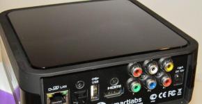
Appearance of an asynchronous electric motor
The section shows the main elements:
- cast-iron case with radiator fins for effective cooling;
- case of a squirrel-cage rotor with magnetic field shift lines relative to its axis;
- switching contact group in a box (boron), for switching the stator windings into star or delta circuits and connecting power supply wires;
- dense bundles of copper wires of the stator winding;
- steel rotor shaft with a groove for fixing the pulley with a wedge-shaped key.
A detailed disassembly of an asynchronous electric motor with all the details is shown in the figure below.

Detailed disassembly of an induction motor
Advantages of generators converted from asynchronous motors:
- ease of assembly of the circuit, the ability not to disassemble the electric motor, not to rewind the windings;
- the possibility of rotation of the electric current generator by a wind or hydro turbine;
- Asynchronous motor generator is widely used in motor-generator systems to convert a single-phase 220V AC network into a three-phase network with a voltage of 380V.
- the possibility of using the generator, in the field spinning it from internal combustion engines.
As a disadvantage, one can note the complexity of calculating the capacitance of capacitors connected to the windings; in fact, this is done experimentally.
Therefore, it is difficult to achieve the maximum power of such a generator, there are difficulties with the power supply of electrical installations that have a large starting current, on circular saws with three-phase AC motors, concrete mixers and other electrical installations.
The principle of operation of the generator
The operation of such a generator is based on the principle of reversibility: "any electrical installation that converts electrical energy into mechanical energy can reverse the process." The principle of operation of generators is used, the rotation of the rotor causes EMF and the appearance of electric current in the stator windings.
Based on this theory, it is obvious that an asynchronous electric motor can be converted into an electric generator. In order to consciously carry out the reconstruction, it is necessary to understand how the generation process takes place and what is required for this. All motors driven by alternating current are considered asynchronous. The stator field moves slightly ahead of the rotor magnetic field, pulling it along in the direction of rotation.
To get the reverse process, generation, the rotor field must be ahead of the movement of the stator magnetic field, in the ideal case, rotate in the opposite direction. This is achieved by including a large capacitor in the power supply network; groups of capacitors are used to increase the capacitance. The capacitor bank is charged by accumulating magnetic energy (an element of the reactive component of the alternating current). The charge of the capacitor is in phase opposite to the current source of the electric motor, so the rotation of the rotor begins to slow down, the stator winding generates current.
transformation
How to practically convert an asynchronous electric motor into a generator with your own hands?
To connect capacitors, it is necessary to unscrew the top cover of the boron (box), where the contact group is located, switching the contacts of the stator windings and the power wires of the asynchronous motor are connected.

Open boron with contact group
The stator windings can be connected in a "Star" or "Delta" circuit.

Connection schemes "Star" and "Triangle"
The nameplate or the product data sheet shows the possible connection diagrams and motor parameters for different connections. It is indicated:
- maximum currents;
- supply voltage;
- power consumption;
- the number of revolutions per minute;
- efficiency and other parameters.

Engine parameters, which are indicated on the nameplate
In a do-it-yourself three-phase generator from an asynchronous electric motor, capacitors are connected in a similar way with a “Triangle” or “Star”.
The option of switching on with the "Star" provides the starting process of generating current at lower speeds than when the circuit is connected to the "Triangle". In this case, the voltage at the output of the generator will be slightly lower. Delta connection provides a slight increase in output voltage, but requires higher RPM to start the generator. In a single-phase asynchronous electric motor, one phase-shifting capacitor is connected.

Connection diagram of capacitors on the generator in the "Triangle"
Capacitors of the KBG-MN model are used, or other brands of at least 400 V non-polar, bipolar electrolytic models are not suitable in this case.

What does a poleless capacitor brand KBG-MN look like
Capacitor capacitance calculation for the motor used
| Rated output power of the generator, in kW | Estimated capacitance in, uF |
|---|---|
| 2 | 60 |
| 3,5 | 100 |
| 5 | 138 |
| 7 | 182 |
| 10 | 245 |
| 15 | 342 |
In synchronous generators, the excitation of the generation process occurs on the armature windings from a current source. 90% of asynchronous motors have squirrel-cage rotors, without winding, excitation is created by the residual static charge in the rotor. It is enough to create an EMF at the initial stage of rotation, which induces a current and recharges the capacitors through the stator windings. Further recharging is already coming from the generated current, the generation process will be continuous while the rotor is rotating.
It is recommended to install the automatic load connection to the generator, sockets and capacitors in a separate closed panel. Lay the connecting wires from the boron generator to the shield in a separate insulated cable.
Even when the generator is not running, it is necessary to avoid touching the terminals of the capacitors of the socket contacts. The charge accumulated by the capacitor remains for a long time and can cause an electric shock. Ground the housings of all units, motor, generator, control panel.
Installation of the motor-generator system
When installing a generator with a motor with your own hands, it must be borne in mind that the indicated number of nominal revolutions of the asynchronous electric motor used at idle is greater.

Scheme of a motor-generator on a belt drive
On an engine of 900 rpm at idle, it will be 1230 rpm, in order to get enough power at the output of the generator converted from this engine, it is necessary to have a number of revolutions 10% more than idle:
1230 + 10% = 1353 rpm.
Belt drive is calculated by the formula:
Vg = Vm x Dm\Dg
Vg - the required rotation speed of the generator 1353 rpm;
Vm - motor rotation speed 1200 rpm;
Dm - pulley diameter on the motor 15 cm;
Dg is the diameter of the pulley on the generator.
Having a motor at 1200 rpm where the pulley is Ø 15 cm, it remains to calculate only Dg - the diameter of the pulley on the generator.
Dg = Vm x Dm / Vg = 1200rpm x 15cm/1353rpm = 13.3 cm.
Generator on neodymium magnets
How to make a generator from an asynchronous electric motor?
This homemade generator eliminates the use of capacitor units. The source of the magnetic field, which induces an EMF and creates a current in the stator winding, is built on permanent neodymium magnets. In order to do this with your own hands, you must sequentially perform the following steps:
- Remove the front and rear covers of the induction motor.
- Remove the rotor from the stator.

What does an induction motor rotor look like?
- The rotor is machined, the top layer is removed by 2 mm more than the thickness of the magnets. At home, it is not always possible to make a rotor boring with your own hands, in the absence of turning equipment and skills. You need to contact the specialists in turning workshops.
- A template is prepared on a sheet of plain paper for placing round magnets, Ø 10-20mm, up to 10 mm thick, with an attraction force of 5-9 kg, per sq / cm, the size depends on the size of the rotor. The template is glued onto the surface of the rotor, the magnets are placed in strips at an angle of 15 - 20 degrees relative to the rotor axis, 8 pieces per strip. The figure below shows that on some rotors there are dark-light stripes of displacement of the magnetic field lines relative to its axis.

Mounting the magnets on the rotor
- The rotor on magnets is calculated so that four groups of strips are obtained, in a group of 5 strips, the distance between the groups is 2Ø of the magnet. The gaps in the group are 0.5-1Ø of the magnet, this arrangement reduces the sticking force of the rotor to the stator, it must be turned by the efforts of two fingers;
- The rotor on magnets, made according to the calculated template, is filled with epoxy resin. After it dries a little, the cylindrical part of the rotor is covered with a layer of fiberglass and impregnated with epoxy again. This will prevent the magnets from flying out when the rotor rotates. The upper layer on the magnets should not exceed the original diameter of the rotor, which was before the groove. Otherwise, the rotor will not fall into place or will rub against the stator winding during rotation.
- After drying, the rotor can be replaced and the covers closed;
- It is necessary to test the electric generator - turn the rotor with an electric drill, measuring the voltage at the output. The number of revolutions when the desired voltage is reached is measured by a tachometer.
- Knowing the required number of revolutions of the generator, the belt drive is calculated using the method described above.
An interesting application is when an electric generator based on an asynchronous electric motor is used in a self-feeding electric motor-generator circuit. When part of the power generated by the generator is supplied to the electric motor, which spins it. The rest of the energy is spent on the payload. By implementing the principle of self-feeding, it is practically possible to provide the house with autonomous power supply for a long time.
Video. G generator from an asynchronous motor.
For a wide range of electricity consumers, it makes no sense to buy powerful diesel power plants like TEKSAN TJ 303 DW5C with an output power of 303 kVA or 242 kW. Low-power gasoline generators are expensive, the best option is to make wind generators with your own hands or a self-feeding motor-generator device.
Using this information, you can assemble a generator with your own hands, on permanent magnets or capacitors. Such equipment is very useful in country houses, in the field, as an emergency power source when there is no voltage in industrial networks. A full-fledged house with air conditioners, electric stoves and heating boilers, they will not pull a powerful circular saw motor. Temporarily provide electricity to essential household appliances, lighting, refrigerator, TV and others that do not require large capacities.
For the needs of building a private residential building or a summer house, a home master may need an autonomous source of electrical energy, which can be bought in a store or assembled with your own hands from available parts.
Homemade generator is able to run on the energy of gasoline, gas or diesel fuel. To do this, it must be connected to the engine through a shock-absorbing clutch that ensures smooth rotation of the rotor.
If local environmental conditions allow, for example, frequent winds blow or a source of running water is nearby, then you can create a wind or hydraulic turbine and connect it to an asynchronous three-phase motor to generate electricity.
Due to such a device, you will have a constantly working alternative source of electricity. It will reduce energy consumption from public networks and allow savings on its payment.
In some cases, it is permissible to use a single-phase voltage to rotate an electric motor and transmit torque to a home-made generator to create its own three-phase symmetrical network.
How to choose an asynchronous motor for a generator by design and characteristics
Technological features
The basis of a homemade generator is a three-phase asynchronous electric motor with:
- phase;
- or squirrel-cage rotor.
Stator device
The magnetic circuits of the stator and rotor are made of insulated plates of electrical steel, in which grooves are created to accommodate the winding wires.

The three individual stator windings can be wired in the factory as follows:
- stars;
- or a triangle.
Their conclusions are connected inside the terminal box and connected with jumpers. The power cable is also installed here.

In some cases, wires and cables can be connected in other ways.

Symmetrical voltages are supplied to each phase of the induction motor, shifted in angle by a third of the circle. They form currents in the windings.

These quantities are conveniently expressed in vector form.

Design features of the rotors
Wound rotor motors
They are provided with a winding modeled on the stator, and the leads from each are connected to slip rings, which provide electrical contact with the start-up and adjustment circuit through pressure brushes.
This design is quite difficult to manufacture, expensive in cost. It requires periodic monitoring of work and qualified maintenance. For these reasons, it makes no sense to use it in this design for a home-made generator.
However, if there is a similar motor and it has no other application, then the conclusions of each winding (those ends that are connected to the rings) can be shorted to each other. In this way, the phase rotor will turn into a short-circuited one. It can be connected according to any scheme considered below.
Squirrel cage motors
Aluminum is poured inside the grooves of the rotor magnetic circuit. The winding is made in the form of a rotating squirrel cage (for which it received such an additional name) with jumper rings short-circuited at the ends.
This is the simplest motor circuit, which is devoid of moving contacts. Due to this, it works for a long time without the intervention of electricians, it is characterized by increased reliability. It is recommended to use it to create a homemade generator.
Designations on the motor housing

In order for a homemade generator to work reliably, you need to pay attention to:
- , which characterizes the quality of protection of the body from the effects of the external environment;
- power consumption;
- speed;
- winding connection diagram;
- permissible load currents;
- Efficiency and cosine φ.

The principle of operation of an induction motor as a generator
Its implementation is based on the method of electric machine reversibility. If the motor is disconnected from the mains voltage, the rotor is forced to rotate at the calculated speed, then EMF will be induced in the stator winding due to the presence of residual energy of the magnetic field.
It remains only to connect a capacitor bank of the appropriate rating to the windings and a capacitive leading current will flow through them, which has the character of a magnetizing one.
In order for the generator to self-excite, and a symmetrical system of three-phase voltages to form on the windings, it is necessary to select the capacitance of the capacitors, which is greater than a certain, critical value. In addition to its value, the design of the engine naturally affects the output power.
For the normal generation of three-phase energy with a frequency of 50 Hz, it is necessary to maintain the rotor speed exceeding the asynchronous component by the amount of slip S, which lies within S=2÷10%. It needs to be kept at the synchronous frequency level.
The deviation of the sinusoid from the standard frequency value will adversely affect the operation of equipment with electric motors: saws, planers, various machine tools and transformers. This has practically no effect on resistive loads with heating elements and incandescent lamps.
Wiring diagrams
In practice, all common methods of connecting the stator windings of an induction motor are used. Choosing one of them creates different conditions for the operation of the equipment and generates a voltage of certain values.
Star schemes
A popular option for connecting capacitors
The connection diagram of an asynchronous motor with star-connected windings for operation as a three-phase network generator has a standard form.

Scheme of an asynchronous generator with connection of capacitors to two windings
This option is quite popular. It allows you to power three groups of consumers from two windings:
- two voltage 220 volts;
- one - 380.

The working and starting capacitors are connected to the circuit by separate switches.
Based on the same circuit, you can create a home-made generator with capacitors connected to one winding of an induction motor.
triangle diagram
When assembling the stator windings according to the star circuit, the generator will produce a three-phase voltage of 380 volts. If you switch them to a triangle, then - 220.

The three schemes shown above in the pictures are basic, but not the only ones. Based on them, other connection methods can be created.
How to calculate the characteristics of the generator by engine power and capacitor capacitance
To create normal operating conditions for an electric machine, it is necessary to observe the equality of its rated voltage and power in the generator and electric motor modes.
For this purpose, the capacitance of the capacitors is selected taking into account the reactive power Q generated by them at various loads. Its value is calculated by the expression:
Q=2π∙f∙C∙U 2
From this formula, knowing the power of the engine, to ensure full load, you can calculate the capacity of the capacitor bank:
C \u003d Q / 2π ∙ f ∙ U 2
However, the mode of operation of the generator should be taken into account. At idle, the capacitors will unnecessarily load the windings and heat them up. This leads to large energy losses, overheating of the structure.
To eliminate this phenomenon, capacitors are connected in steps, determining their number depending on the applied load. To simplify the selection of capacitors for starting an asynchronous motor in generator mode, a special table has been created.
| Generator power (kVA) | Full load mode | Idle mode | ||||
| cos φ=0.8 | cos φ=1 | Q (kvar) | C (uF) | |||
| Q (kvar) | C (uF) | Q (kvar) | C (uF) | |||
| 15 | 15,5 | 342 | 7,8 | 172 | 5,44 | 120 |
| 10 | 11,1 | 245 | 5,9 | 130 | 4,18 | 92 |
| 7 | 8,25 | 182 | 4,44 | 98 | 3,36 | 74 |
| 5 | 6,25 | 138 | 3,4 | 75 | 2,72 | 60 |
| 3,5 | 4,53 | 100 | 2,54 | 56 | 2,04 | 45 |
| 2 | 2,72 | 60 | 1,63 | 36 | 1,27 | 28 |
Starting capacitors of the K78-17 series and the like with an operating voltage of 400 volts or more are well suited for use as part of a capacitive battery. It is quite acceptable to replace them with metal-paper counterparts with the corresponding denominations. They will have to be connected in parallel.

It is not worth using models of electrolytic capacitors to work in the circuits of an asynchronous home-made generator. They are designed for DC circuits, and when passing a sinusoid that changes in direction, they quickly fail.
There is a special scheme for connecting them for such purposes, when each half-wave is directed by diodes to its assembly. But it's pretty complicated.
Design
The autonomous device of the power plant must fully provide the operating equipment and be carried out by a single module, including a hinged electrical panel with devices:
- measurements - with a voltmeter up to 500 volts and a frequency meter;
- switching loads - three switches (one general supplies voltage from the generator to the consumer circuit, and the other two connect capacitors);
- protection - eliminating the consequences of short circuits or overloads and), saving workers from insulation breakdown and phase potential entering the housing.
Main power redundancy
When creating a home-made generator, it is necessary to provide for its compatibility with the grounding circuit of the working equipment, and for autonomous operation, it must be securely connected to.
If the power plant is created for backup power supply of devices operating from the state network, then it should be used when the voltage is disconnected from the line, and when restored, it should be stopped. To this end, it is enough to install a switch that controls all phases simultaneously or connect a complex automatic system for switching on backup power.
Voltage selection
The 380 volt circuit has an increased risk of human injury. It is used in extreme cases, when it is not possible to get by with a phase value of 220.
Generator overload
Such modes create excessive heating of the windings with subsequent destruction of the insulation. They occur when the currents passing through the windings are exceeded due to:
- improper selection of capacitor capacitance;
- connection of high power consumers.
In the first case, it is necessary to carefully monitor the thermal regime during idling. With excessive heating, it is necessary to adjust the capacitance of the capacitors.
Features of connecting consumers
The total power of a three-phase generator consists of three parts generated in each phase, which is 1/3 of the total. The current passing through one winding must not exceed the rated value. This must be taken into account when connecting consumers, distribute them evenly over the phases.
When a homemade generator is designed to operate on two phases, then it cannot safely generate electricity more than 2/3 of the total value, and if only one phase is involved, then only 1/3.
Frequency control
The frequency meter allows you to monitor this indicator. When it was not installed in the design of a home-made generator, then you can use the indirect method: at idle, the output voltage exceeds the nominal 380/220 by 4 ÷ 6% at a frequency of 50 Hz.
One of the options for making a home-made generator from an asynchronous motor and its capabilities are shown in their video by the owners of the Maria channel with Alexander Kostenko.
(13 votes, average: 4.5 out of 5)
I found an article on the Internet on how to convert a car generator to a permanent magnet generator. Is it possible to use this principle and remake the generator with your own hands from an asynchronous electric motor? It is possible that there will be large energy losses, not such an arrangement of coils.
I have an asynchronous type motor for a voltage of 110 volts, revolutions - 1450, 2.2 amperes, single-phase. With the help of containers, I do not undertake to make a home-made generator, as there will be large losses.
It is proposed to use simple engines according to this scheme.
If you change the engine or generator with rounded magnets from the speakers, then you need to install them in crabs? Crabs are two metal parts, anchored outside the excitation coils.
If magnets are put on the shaft, then the shaft will shunt the magnetic lines of force. How then will the excitement be? The coil is also located on a metal shaft.
If you change the connection of the windings and make a parallel connection, accelerate to a speed above normal values, then you get 70 volts. Where can I get a mechanism for such revolutions? If you rewind it to a decrease in speed and lower power, then the power will drop too much.
An induction motor with a closed rotor is iron, which is filled with aluminum. You can take a homemade generator from a car, which has a voltage of 14 volts, a current of 80 amperes. This is good data. An engine with an alternating current collector from a vacuum cleaner or washing machine can be used for a generator. Install bias on the stator, remove the DC voltage from the brushes. According to the highest EMF, change the angle of the brushes. The efficiency tends to zero. But, better than a synchronous type generator, they did not invent.
I decided to try a homemade generator. A single-phase asynchronous motor from a baby washer twisted with a drill. I connected a capacitance of 4 microfarads to it, it turned out 5 volts 30 hertz and a current of 1.5 milliamps for a short circuit.
Not every electric motor can be used as a generator in this way. There are motors with a steel rotor that have a low degree of magnetization on the remainder.
It is necessary to know the difference between electrical energy conversion and energy generation. There are several ways to convert 1 phase to 3. One of them is mechanical energy. If the power plant is disconnected from the socket, then all conversion is lost.
It is clear where the movement of the wire with an increase in speed comes from. Where the magnetic field will be to obtain the EMF in the wire is not clear.
It's easy to explain. Due to the mechanism of magnetism that remains, an EMF is formed in the armature. There is a current in the stator winding, which is closed to the capacitance.
The current has arisen, which means that it gives an increase in the electromotive force on the coils of the rotor shaft. The emerging current gives an increase in the electromotive force. The stator electric current generates much more electromotive force. This goes until the equilibrium of the stator magnetic fluxes and the rotor is established, as well as additional losses.
The size of the capacitors is calculated so that the voltage at the terminals reaches the nominal value. If it is small, then reduce the capacity, then increase it. There were doubts about the old motors, which supposedly are not excited. After accelerating the rotor of a motor or generator, it is necessary to poke quickly into any phase with a small amount of volts. Everything will return to normal. Charge the capacitor to a voltage equal to half the capacitance. Turn on with a three-pole switch. This applies to a 3-phase motor. Such a scheme is used for generators of passenger transport cars, since they have a squirrel-cage rotor.
Method 2
You can make a homemade generator in another way. The stator has a tricky design (has a special design solution), it is possible to adjust the output voltage. I made a generator of this kind with my own hands at the construction site. The engine took a power of 7 kW at 900 rpm. I connected the excitation winding according to the triangle circuit for 220 V. I started it at 1600 revolutions, the capacitors were 3 at 120 microfarads. They were switched on by a contactor with three poles. The generator acted as a three-phase rectifier. From this rectifier, an electric drill with a 1000-watt collector was fed, and a circular saw for 2200 watts, 220 V, grinder 2000 watts.
I had to make a soft start system, another resistor with a shorted phase after 3 seconds.
For motors with manifolds, this is not correct. If the rotating frequency is doubled, then the capacitance will also decrease.
The frequency will also increase. The tank circuit was switched off in automatic mode so as not to use the reactivity torus, not to consume fuel.

During operation, it is necessary to press the stator of the contactor. Three phases dismantled them out of uselessness. The reason lies in the high gap and increased field dissipation of the poles.
Special mechanisms with a double cage for squirrels and slanting eyes for squirrels. Still, I received 100 volts and a frequency of 30 hertz from the washing machine motor, the 15-watt lamp does not want to burn. Very weak power. It is necessary to take the motor stronger, or put more capacitors.
Under the wagons, a generator with a squirrel-cage rotor is used. Its mechanism comes from a gearbox and a belt drive. Turns of rotation 300 turns. It is located as an additional load generator.
Method 3
You can design a homemade generator, a gasoline power plant.

Instead of a generator, use a 1.5 kW 3-phase asynchronous motor at 900 rpm. The electric motor is Italian, it can be connected with a triangle and a star. First, I put the motor on a base with a DC motor, connected it to the coupling. Started turning the engine at 1100 rpm. There was a voltage of 250 volts on the phases. I connected a 1000 watt light bulb, the voltage immediately dropped to 150 volts. It's probably due to phase imbalance. Each phase must be connected to a separate load. Three light bulbs of 300 watts will not be able to reduce the voltage to 200 volts, theoretically. You can put more capacitor.
The engine speed must be increased, do not reduce under load, then the power supply to the network will be constant.
Significant power is needed, the autogenerator will not give such power. If you rewind a large KAMAZ one, then 220 V will not come out of it, since the magnetic circuit will be oversaturated. It was designed for 24 volts.
Today I was going to try to connect the load through a 3-phase power supply (rectifier). The lights were turned off in the garages, it didn't work. In the city of power engineers, the electricity is systematically turned off, so it is necessary to make a source of constant power supply with electricity. For electric welding there is a hitch, it is hooked to the tractor. To connect an electric tool, you need a constant voltage source of 220 V. There was an idea to design a home-made generator with your own hands, and an inverter to it, but you can’t work on batteries for a long time.
The electricity was recently turned on. I connected an asynchronous motor from Italy. I put it with the chainsaw motor on the frame, twisted the shafts together, put a rubber clutch. I connected the coils according to the star scheme, the capacitors in a triangle, 15 microfarads each. When I started the motors, the power output did not work. I attached a capacitor charged to the phases, the voltage appeared. The engine gave out its power of 1.5 kW. At the same time, the supply voltage dropped to 240 volts, at idle it was 255 volts. The grinder from him worked fine at 950 watts.
I tried to increase the engine speed, but the excitation does not work. After the contact of the capacitor with the phase, the voltage appears immediately. I will try to install another engine.
What system designs are produced abroad for power plants? On 1-phase, it is clear that the rotor owns the winding, there is no phase imbalance, because there is one phase. In 3-phase, there is a system that gives power adjustment when motors with the highest load are connected to it. You can also connect an inverter for welding.
Over the weekend I wanted to make a homemade generator with my own hands with an asynchronous motor connected. A successful attempt to make a home-made generator turned out to be the connection of an old engine with a cast iron housing for 1 kW and 950 rpm. The motor is excited normally, with one capacitance of 40 uF. And I installed three containers and connected them with a star. This was enough to start an electric drill, a grinder. I wanted to get the output of voltage on one phase. To do this, I connected three diodes, a half-bridge. The fluorescent lamps for lighting burned out, and the bags in the garage burned out. I will wind the transformer in three phases.
Write comments, additions to the article, maybe I missed something. Take a look at , I will be glad if you find something else useful on mine.
An asynchronous or induction type generator is a special kind of device that uses alternating current and has the ability to reproduce electricity. The main feature is the rather fast turns that the rotor makes; in terms of the rotation speed of this element, it largely exceeds the synchronous variety.
One of the main advantages is the ability to use this device without significant circuit changes or lengthy tuning.
A single-phase version of the induction generator can be connected by supplying the necessary voltage to it, this will require connecting it to a power source. However, a number of models produce self-excitation, this ability allows them to operate in a mode independent of any external sources.
This is done by sequentially bringing the capacitors into working condition.
Scheme of a generator from an induction motor
 generator circuit based on an asynchronous motor
 In virtually any electrical type machine designed as a generator, there are 2 different active windings, without which the device cannot function:
- Excitation winding, which is located on a special anchor.
- Stator winding, which is responsible for the formation of electric current, this process occurs inside it.
In order to visualize and more accurately understand all the processes that occur during the operation of the generator, the best option would be to consider in more detail the scheme of its operation:
- Voltage, which is supplied from a battery or any other source, creates a magnetic field in the armature winding.
- Rotation of device elements together with a magnetic field can be implemented in various ways, including manually.
- A magnetic field, rotating at a certain speed, generates electromagnetic induction, due to which an electric current appears in the winding.
- The vast majority of schemes in use today does not have the ability to provide the armature winding with voltage, this is due to the presence of a squirrel-cage rotor in the design. Therefore, regardless of the speed and time of rotation of the shaft, the power devices will still be de-energized.
When converting an engine into a generator, the independent creation of a moving magnetic field is one of the main and indispensable conditions.
Generator device

Before taking any action to remakeinto the generator, you need to understand the device of this machine, which looks like this:
- stator, which is equipped with a network winding with 3 phases, placed on its working surface.
- Winding organized in such a way that it resembles a star in its shape: 3 initial elements are connected to each other, and 3 opposite sides are connected to slip rings that have no points of contact with each other.
- slip rings have a reliable fastening to the rotor shaft.
- In design there are special brushes that do not make any independent movements, but contribute to the inclusion of a three-phase rheostat. This allows you to change the resistance parameters of the winding located on the rotor.
- Often, in the internal device there is such an element as an automatic short-circuiter, which is necessary in order to short-circuit the winding and stop the rheostat, which is in working condition.
- Another additional element of the generator device may be a special device that separates the brushes and slip rings at the moment when they go through the closing stage. Such a measure contributes to a significant reduction in friction losses.
Making a generator from an engine
 In fact, any asynchronous electric motor can be converted with your own hands into a device that functions like a generator, which can then be used in everyday life. Even an engine taken from an old-style washing machine or any other household equipment may be suitable for this purpose.
In order for this process to be successfully implemented, it is recommended to adhere to the following algorithm of actions:
- Remove the motor core layer, due to which a recess will be formed in its structure. This can be done on a lathe, it is recommended to remove 2 mm. around the core and make additional holes with a depth of about 5 mm.
- Take measurements from the resulting rotor, after which a template in the form of a strip is made from tin material, which will correspond to the dimensions of the device.
- Install in the resulting free space, neodymium magnets, which must be purchased in advance. At least 8 magnetic elements are required for each pole.
- fixing magnets can be done using universal superglue, but it must be borne in mind that when approaching the surface of the rotor, they will change their position, so they must be firmly held by hand until each element is glued. In addition, it is recommended to use protective goggles during this process to avoid splashing glue into the eyes.
- wrap rotor plain paper and tape, which will be required to fix it.
- End part of the rotor close up with plasticine, which will ensure the sealing of the device.
- After the actions it is necessary to process the free cavities between the magnetic elements. To do this, the remaining free space between the magnets must be filled with epoxy. It will be most convenient to cut a special hole in the shell, convert it into a neck and close the borders with plasticine. Resin can be poured inside.
- Wait for complete solidification poured resin, after which the protective paper shell can be removed.
- The rotor needs to be fixed using a machine tool or a vice, so that it can be processed, which consists in grinding the surface. For these purposes, you can use sandpaper with a medium grit parameter.
- Define state and the purpose of the wires coming out of the engine. Two should lead to the working winding, the rest can be cut off so as not to get confused in the future.
- Sometimes the rotation process is carried out quite poorly, most often the cause is old worn and tight bearings, in which case they can be replaced with new ones.
- Rectifier for generator can be assembled from special silicon, which are designed specifically for these purposes. Also, you do not need a controller for charging, virtually all modern models are suitable.
After performing all the above actions, the process can be considered completed, the asynchronous motor was converted into a generator of the same type.
Evaluation of the level of efficiency - is it profitable?
 The generation of electric current by an electric motor is quite real and feasible in practice, the main question is how profitable it is?
Comparison is carried out primarily with a synchronous version of a similar device, in which there is no electrical excitation circuit, but despite this fact, its device and design are not simpler.
This is due to the presence of a capacitor bank, which is an extremely technically complex element that an asynchronous generator does not have.
The main advantage of the asynchronous device is that the available capacitors do not require any maintenance, since all the energy is transferred from the magnetic field of the rotor and the current that is generated during the operation of the generator.
The electric current generated during operation has virtually no higher harmonics, which is another significant advantage.
Asynchronous devices do not have other advantages, except for those mentioned, but they have a number of significant disadvantages:
- During their operation there is no possibility to ensure the nominal industrial parameters of the electric current that is generated by the generator.
- High degree of sensitivity even the slightest fluctuations in workload parameters.
- If the parameters of the permissible loads on the generator are exceeded, a shortage of electricity will be detected, after which recharging will become impossible and the generation process will be stopped. To eliminate this disadvantage, batteries with a significant capacity are often used, which have the feature of changing their volume depending on the magnitude of the loads exerted.
The electric current generated by an asynchronous generator is subject to frequent changes, the nature of which is unknown, it is random and cannot be explained by scientific arguments.
The impossibility of taking into account and appropriate compensation for such changes explains the fact that such devices have not gained popularity and are not widely used in the most serious industries or household chores.
Functioning of an induction motor as a generator
 In accordance with the principles by which all such machines operate, the operation of an asynchronous motor after conversion into a generator occurs as follows:
- After connecting the capacitors to the terminals, a number of processes take place on the stator winding. In particular, a leading current begins to move in the winding, which creates the effect of magnetization.
- Only when matching capacitors parameters of the required capacity, the device self-excites. This contributes to a symmetrical voltage system with 3 phases on the stator winding.
- Final voltage value will depend on the technical capabilities of the machine used, as well as on the capabilities of the capacitors used.
Thanks to the described actions, the process of converting a squirrel-cage induction motor into a generator with similar characteristics takes place.
Application
In everyday life and at work, such generators are widely used in various fields and areas, but they are most in demand to perform the following functions:
- Use as engines for , this is one of the more popular features. Many people make their own asynchronous generators to use them for this purpose.
- Work as a hydroelectric power plant with little output.
- Nutrition and electricity from a city apartment, a private country house or individual household equipment.
- Performing basic functions welding generator.
- Uninterrupted Equipment alternating current of individual consumers.

It is necessary to have certain skills and knowledge not only in the manufacture, but also in the operation of such machines, the following tips can help with this:
- Any kind of asynchronous generators regardless of the area in which they are used, is a dangerous device, for this reason it is recommended to insulate it.
- During the manufacturing process it is necessary to consider the installation of measuring instruments, since it will be necessary to obtain data on its functioning and operating parameters.
- Availability of special buttons, with which you can control the device, greatly facilitates the operation process.
- grounding is a mandatory requirement that must be implemented prior to the operation of the generator.
- During work, the efficiency of an asynchronous device can periodically decrease by 30-50%, it is not possible to overcome the occurrence of this problem, since this process is an integral part of energy conversion.
To make a wind generator with a power of up to 1 kW with your own hands, there is no need to purchase special equipment. This problem is easy to solve with an asynchronous motor. Moreover, the specified power will be quite enough to create conditions for the operation of individual household appliances and connect street lighting in the garden in the country.
If you make a windmill with your own hands, then you will have a free source of energy that you can use at your discretion. Any home master is able to make their own wind generator based on an asynchronous motor.
What is a generator made of?
The generator set, which will generate electricity, provides for the following main elements:

Principle of operation
 Operation of homemade windmills carried out by analogy with wind turbines that are used in industry. The main goal is to generate an alternating voltage, for which kinetic energy is transformed into electrical energy. The wind drives the rotor-type wind wheel, as a result of which the resulting energy flows from it to the generator. And usually the role of the latter is performed by an asynchronous motor.
As a result of the creation of a current generator, the latter enters the battery, which is equipped with a module and a charge controller. From there, it is sent to a DC voltage inverter, the source of which is the mains. As a result manages to create a voltage, whose characteristics are suitable for domestic use (220 V 50 Hz).
A controller is used to transform AC voltage into DC. It is with its help that the batteries are charged. In some cases, inverters are capable of performing the functions of an uninterruptible power supply. In other words, in case of problems with the supply of electricity, they can use batteries or generators as a power source for household devices.
Materials and tools
To make a wind generator enough to have an asynchronous motor, which will have to be redone. At the same time, you will have to stock up on a number of materials:

Characteristics and installation of the generator
The generator has the following characteristics:

Mounting Features
 Most often, do-it-yourself generator installation is carried out using a three-blade wind wheel, reaching a diameter of about 2 m. The decision to increase the number of blades or their length does not lead to an improvement in performance. Regardless of the option chosen regarding the configuration, dimensions and shape of the blades, preliminary calculations should be performed first.
During self-installation, you need to pay attention to such a parameter as the condition of the soil of the site where the support and stretch marks will be placed. The mast is installed by digging a hole with a depth of not more than 0.5 m, which must be filled with concrete mortar.
Network connection carried out in a strictly defined order.: the batteries are connected first, and the wind generator itself follows them.
The rotation of the wind turbine can be carried out in a horizontal or vertical plane. In this case, the choice is usually stopped on a vertical plane, which is associated with the design. It is permissible to use the Darier and Savonius models as rotors.
Sealing gaskets or a cap must be used in the design of the installation. Thanks to this solution, moisture will not harm the generator.
An open area must be chosen for the placement of the mast and support. A suitable height for a mast is 15 m. masts are most widely used whose height does not exceed 5-7 m.
It is optimal if a self-made wind generator acts as a backup power source.
These installations have restrictions on their use, since their operation is possible only in those regions where the wind speed reaches about 7-8 m/s.
Before you start creating a windmill with your own hands, perform accurate calculations. In some cases, there are difficulties in processing the nodes of an induction motor;
A windmill cannot be created without electrical modules, as well as a series of experiments.
How to make an asynchronous generator with your own hands?
 Although, always you can buy a ready-made asynchronous generator, you can go the other way and save money by making it yourself. Difficulties will not arise here. The only thing to do is prepare the necessary tools.
- One of the features of the generator is that it should spin faster than an engine. This can be achieved in the following way. After starting, you need to find out the speed of rotation of the engine. In solving this problem, a tachogenerator or a tachometer will help us
- Having determined the above parameter, 10% should be added to the value. If, for example, its torque is 1200 rpm, then for the generator it will be 1320 rpm.
- To make an electric generator based on an induction motor, you will need to find a suitable capacitance for capacitors. Moreover, it should be remembered that all capacitors must not differ in their phases from each other.
- It is recommended to use a medium sized container. If it turns out to be too large, then this will lead to heating of the asynchronous motor.
- For Assembly capacitors should be used, which can guarantee the desired rotation speed. Their installation must be taken with great seriousness. It is recommended to protect them using special insulating materials.
These are all the operations that must be performed when arranging a generator based on an engine. Then you can proceed to its installation. Be aware that when using a device equipped with a squirrel-cage rotor, you will receive high voltage current. For this reason, in order to achieve a value of 220 V, you will need a step-down transformer.