The principle of operation of a Tesla generator circuit for 220V. Musical tesla coil circuit
In 1891, Nikola Tesla developed a transformer (coil) with which he experimented with high-voltage electrical discharges. The device Tesla developed consisted of a power supply, a capacitor, primary and secondary coils arranged so that voltage peaks alternate between them, and two electrodes separated by a distance. The device received the name of its inventor.
The principles discovered by Tesla using this device are now used in various fields, from particle accelerators to televisions and toys.
Tesla transformer can be made with his own hands. This article is devoted to addressing this issue.
First you need to decide on the size of the transformer. You can build a large device if your budget allows. It should be remembered that this device generates high voltage discharges (creating microlightning), which heat and expand the surrounding air (creating microthunder). The electric fields created can damage other electrical devices. Therefore, it is not worth building and running a Tesla transformer at home; It's safer to do this in a remote location, such as a garage or shed.
The size of the transformer will depend on the distance between the electrodes (on the size of the resulting spark), which in turn will depend on the power consumption.
Components and assembly of the Tesla transformer circuit
- We will need a transformer or generator with a voltage of 5-15 kV and a current of 30-100 milliamps. The experiment will fail if these parameters are not met.
- The current source must be connected to the capacitor. The capacitance parameter of the capacitor is important, i.e. ability to hold an electrical charge. The unit of capacitance is the farad - F. It is defined as 1 ampere-second (or coulomb) per 1 volt. Typically, capacitance is measured in small units - μF (one millionth of a farad) or pF (one trillionth of a farad). For a voltage of 5 kV, the capacitor should have a rating of 2200 pF.
- The capacitor(s) is connected to a spark plug - a gap of air between the contacts of which an electrical breakdown occurs. In order for the contacts to withstand the heat generated by the spark during the discharge, their required diameter must be 6 mm. minimum. A spark plug is necessary to excite resonant oscillations in the circuit.
- Primary coil. Made from thick copper wire or tube with a diameter of 2.5-6 mm, which is twisted into a spiral in one plane in the amount of 4-6 turns
- The primary coil is connected to the arrester. The capacitor and primary coil must form a primary circuit that is in resonance with the secondary coil.
- The primary coil must be well insulated from the secondary.
- Secondary coil. Made from thin enameled copper wire (up to 0.6 mm). The wire is wound onto a polymer tube with an empty core. The height of the tube should be 5-6 times its diameter. 1000 turns should be carefully wound onto the tube. The secondary coil can be placed inside the primary coil.
- The secondary coil at one end must be grounded separately from other devices. It is best to ground directly “to the ground”. The second wire of the secondary coil is connected to the torus (lightning emitter).
- The torus can be made from ordinary ventilation corrugation. It is placed above the secondary coil.
- The secondary coil and the torus form the secondary circuit.
- We turn on the supply generator (transformer). Tesla transformer works.
It's even better to connect several capacitors in series. In this case, each capacitor will retain part of the charge, the total retained charge will increase multiple.
Excellent video explaining how the Tesla transformer works
Precautionary measures
Be careful: the voltage accumulated in the Tesla transformer is very high and, in the event of a breakdown, leads to guaranteed death. The current strength is also very high, far exceeding the value safe for life.
There is no practical use of the Tesla transformer. This is an experimental setup that confirms our knowledge of the physics of electricity.
From an aesthetic point of view, the effects generated by the Tesla transformer are amazing and beautiful. They largely depend on how correctly it is assembled, whether the current is sufficient, and whether the circuits resonate correctly. The effects may include a glow or discharges formed on the second coil, or they may include full-fledged lightning piercing the air from the torus. The resulting glow is shifted to the ultraviolet range of the spectrum.
A high-frequency field is formed around the Tesla transformer. Therefore, for example, when an energy-saving light bulb is placed in this field, it begins to glow. The same field leads to the formation of large amounts of ozone.
The Tesla Transformer is a device invented by Nikola Tesla and bearing his name. It is a resonant transformer that produces high voltage and high frequency. The device was claimed by a US patent dated September 22, 1896, as “Apparatus for producing electric currents of high frequency and potential.”
The simplest Tesla transformer consists of two coils - primary and secondary, as well as a spark gap, a capacitor, a toroid (not always used) and a terminal (shown as “output” in the diagram).
The primary coil usually contains several turns of large diameter wire or copper tubing, and the secondary coil usually contains about 1000 turns of smaller diameter wire. The primary coil can be flat (horizontal), conical or cylindrical (vertical). Unlike conventional transformers, there is no ferromagnetic core. Thus, the mutual inductance between the two coils is much less than that of transformers with a ferromagnetic core. The primary coil, together with the capacitor, forms an oscillatory circuit, which includes a nonlinear element - a spark gap.
The spark gap, in the simplest case an ordinary gas one, consists of two massive electrodes with an adjustable gap. The electrodes must be resistant to the flow of large currents through the electric arc between them and have good cooling.
The secondary coil also forms an oscillatory circuit, where the role of a capacitor is mainly played by the capacitance of the toroid and the own interturn capacitance of the coil itself. The secondary winding is often coated with a layer of epoxy resin or varnish to prevent electrical breakdown.
The terminal can be made in the form of a disk, a sharpened pin or a sphere and is designed to produce predictable spark discharges of long length.
Thus, the Tesla transformer consists of two connected oscillatory circuits, which determines its remarkable properties and is its main difference from conventional transformers. For full operation of the transformer, these two oscillatory circuits must be tuned to the same resonant frequency. Typically, during the tuning process, the primary circuit is adjusted to the frequency of the secondary by changing the capacitance of the capacitor and the number of turns of the primary winding until the maximum voltage is obtained at the output of the transformer.
1. TESLA TRANSFORMER DIAGRAM
As you can see, this diagram has a minimum of elements, which does not make our task any easier. After all, for it to work, you need to not only assemble it, but also configure it! Let's start in order:
MOTS: there is such a transformer in the microwave. It is a regular power transformer with the only difference that its core operates in a mode close to saturation. This means that despite its small size, it has a power of up to 1.5 kW. However, there are also negative aspects to this mode of operation. This includes a high idle current, about 2-4 A, and strong heating even without a load; I am silent about heating with a load. The usual output voltage of the MOT is 2000-2200 volts with a current of 500-850 mA.
For all MOTs, the “primary” is wound at the bottom, the “secondary” at the top. This is done to ensure good insulation of the windings. On the “secondary”, and sometimes on the “primary”, the filament winding of the magnetron is wound, about 3.6 volts. Moreover, between the windings you can see two metal jumpers. These are magnetic shunts. Their main purpose is to close part of the magnetic flux created by the “primary” and thus limit the magnetic flux through the “secondary” and its output current at a certain level. This is done due to the fact that in the absence of shunts, during a short circuit in the “secondary” (during an arc), the current through the “primary” increases many times and is limited only by its resistance, which is already very small. Thus, the shunts prevent the trans from overheating quickly when the load is connected. Although the MOT gets hot, they put a good fan in the stove to cool it and it doesn’t die. If the shunts are removed, then the power delivered by the trans increases, but overheating occurs much faster. Shunts on imported MOTs are usually well filled with epoxy and are not so easy to remove. But it is still advisable to do this; the drawdown under load will be reduced. To reduce the heat, I can recommend putting the MOT in the oil.
I ask amateurs to refuse this work. Danger High voltage. Lethal to life.
Although the voltage is small compared to the line, the current strength, a hundred times greater than the safe limit of 10 mA, will make your chances of staying alive almost equal to zero.
I can upset some people by reporting that MOT, although an ideal power source for Tesla coils (small-sized, powerful, does not die from RF like NST), but its price ranges from 600 to 1500 or more rubles. In addition, even if you have that kind of money, you will have to run around radio markets and stores quite a bit in search of it. Personally, I have never found an imported ILO, neither new nor used. But I found an MOT from the Soviet Electronika microwave oven. It is much larger in size than imported ones and works like a regular trans. It is called from TV-11-3-220-50. Its approximate parameters: power about 1.5 kW, output voltage ~2200 volts, current 800 mA. Decent parameters. Moreover, on it, in addition to the primary, secondary and filament, there is also a 12 V winding, just to power the cooler for the Tesla spark generator.
CAPS: This means high-voltage ceramic capacitors (series K15U1, K15U2, TGK, KTK, K15-11, K15-14 - for high-frequency installations!) The most difficult thing is to find them. We present an identikit:
HF filter: respectively, two coils that perform the function of filters from high frequency voltage. Each contains 140 turns of varnished copper wire 0.5 mm in diameter.
Very clearly visible in this figure:
Iskrovik: Iskrovik is needed to switch the power supply and excite oscillations in the circuit. If there is no spark switch in the circuit, then there will be power, but there will be no oscillations. And the power supply begins to siphon through the primary - and this is a short circuit! As long as the spark switch is not closed, the caps are charging. As soon as it closes, oscillations begin. Therefore, they install ballast in the form of throttles - when the spark plug is closed, the throttle prevents the flow of current from the power supply, it charges itself, and then, when the spark gap opens, it charges the caps with redoubled anger. Yes, if the socket had 200 kHz, the arrester would naturally not be needed.
Finally, the turn has come to the Tesla transformer itself: the primary winding consists of 7-9 turns of wire of a very large cross-section, but a plumbing copper tube will do. The secondary winding contains from 400 to 800 turns, here you need to adjust. Power is supplied to the primary winding. The secondary has one terminal reliably grounded, the second is connected to the TORU (lightning emitter). The torus can be made from ventilation corrugation.
That's all. Remember safety. And I wish you good luck
In this video tutorial of the youtube channel “Alpha Mods” we will assemble a small singing kacher from a purchased Chinese kit, sold in this Chinese store.
Tesla music driver circuit
The bag contains all the necessary parts. Secondary coil, metal ball for discharge, power supply. Let's start the assembly with small components. Precisely from resistors. 3, which is in place, at 22 kilo-ohms. R5, r3 and r2. Everything is indicated on the board, so we just leave it and wash it down. We solder other resistors in the same way. Next came the capacitors. We solder them too. Then LEDs, 1 blue, 2 red. Finally, mosfet and cooling. To easily replace the transistors, the master used a dip panel. But with it the transistor stands a little higher, the holes on the cooler do not match. We are finalizing it. Next we solder the switch.


Here the master accidentally soldered 2 contacts of the switch together. If you ever run into this problem, you need to either blow hard or buy a tool. This suction is sold in a Chinese store. It costs less than 4 dollars. We heat the contacts with a soldering iron, press the button on the desoldering pump, the contact is updated. Finally we solder the primary coil and the secondary. We start the power supply.
Due to the low current consumption, you can make a USB cacher.
Now we take the adapter from the kit for 12 volts, 2 amperes. We connect the circuit to it. The constructor is ready. But let's make it a musical qualityr.
Let's add a couple of details. And a 3.5 minijack appears. We take a smartphone, download the pulse generation application and here you have modulation. You can also connect music in the same way. Someone will say: I can’t hear anything! But this is played by the Streamer on the streamer. Now we take a syringe, screw a self-tapping screw into the nozzle and create a vacuum.
Meet the next Tesla coil. This is a Kacher. Until that moment, I didn’t perceive kachers as a circuit at all; none of them worked for me until they recommended this option powered from a 220-volt household network. His diagram:
But I didn’t have the required field-effect transistor, or rather, I didn’t have any field-effect transistors at all, and so I decided to install a bipolar, but quite powerful transistor D13009K. The Kacher cannot work directly from the network since the transistor, no matter what it is, will burn out anyway, for this they install a diode to rectify one half-cycle and a power supply choke with a resistance of several tens of Ohms.

Bipolar transistors have a higher transition resistance than field-effect transistors, so I decided to limit the current even more. I placed a 1kOhm resistor on the power supply and a 1uF capacitor in parallel with it. Thanks to the capacitor, the kacher began to work in pulses and the transistor stopped heating completely. Even without a radiator it was absolutely cold, but just in case I screwed it to a small plate. Next, during the assembly process, I installed another 5 μF capacitor in parallel with the power supply.

Zener diodes VD1 and VD2 protect the gate (base) of the transistor from voltage surges; they can also be replaced with one suppressor. I replaced the 1k resistor with a small transformer; its primary winding was 1kOhm, since the resistor got quite hot.

I assembled all the elements of the kacher in a canopy, tested them and decided to place them in the case. For the body I chose a thick plastic cup for instant puree.

I cut out the bottom for the cup from thick cardboard and installed everything on it - the transformer and the rest of the radio elements.


During the assembly, I added a thermistor, whose resistance increases many times when heated. And glued it to the radiator. Suddenly, after a couple of hours of operation, the transistor will boil, and the thermistor will work and stop passing current - the circuit will turn off...


The discharge turned out to be about 3 centimeters and is very similar to real lightning or a spark with SGTC. In general, the scheme is quite simple, and I think it will not cause any particular difficulties even for beginners. The main reason for the malfunction may be incorrect phrasing of the windings; it is enough to simply swap the leads of the primary winding. It is also necessary to check whether the secondary winding is “grounded” to the base (gate) of the transistor - this is very important, because The secondary winding simultaneously plays the role of feedback loop. And of course, a video of the cameraman working.
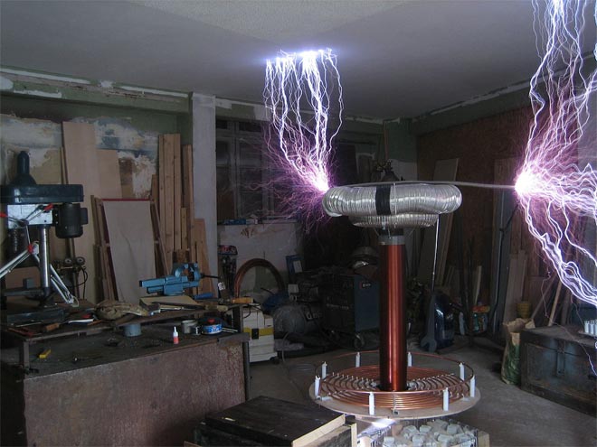
A transformer that increases voltage and frequency many times is called a Tesla transformer. Energy-saving and fluorescent lamps, picture tubes of old TVs, charging batteries from a distance and much more were created thanks to the operating principle of this device. Let’s not exclude its use for entertainment purposes, because the “Tesla transformer” is capable of creating beautiful purple discharges - streamers reminiscent of lightning (Fig. 1). During operation, an electromagnetic field is formed that can affect electronic devices and even the human body, and during discharges in the air a chemical process occurs with the release of ozone. To make a Tesla transformer with your own hands, you do not need to have extensive knowledge in the field of electronics, just follow this article.
Components and operating principle
All Tesla transformers, due to a similar operating principle, consist of identical blocks:
- Power supply.
- Primary circuit.

The power supply provides the primary circuit with voltage of the required magnitude and type. The primary circuit creates high-frequency oscillations that generate resonant oscillations in the secondary circuit. As a result, a current of high voltage and frequency is formed on the secondary winding, which tends to create an electrical circuit through the air - a streamer is formed.
The choice of primary circuit determines the type of Tesla coil, power source and size of the streamer. Let's focus on the semiconductor type. It features a simple circuit with accessible parts and a low supply voltage.
Selection of materials and parts
We will search and select parts for each of the above structural units:


After winding, we insulate the secondary coil with paint, varnish or other dielectric. This will prevent the streamer from getting into it.
Terminal – additional capacity of the secondary circuit, connected in series. For small streamers it is not necessary. It is enough to bring the end of the coil up 0.5–5 cm.
After we have collected all the necessary parts for the Tesla coil, we begin to assemble the structure with our own hands.
Design and assembly
We carry out the assembly according to the simplest scheme in Figure 4.

We install the power supply separately. The parts can be assembled by hanging installation, the main thing is to avoid short circuits between the contacts.
When connecting a transistor, it is important not to mix up the contacts (Fig. 5).

To do this, we check the diagram. We tightly screw the radiator to the transistor body.
Assemble the circuit on a dielectric substrate: a piece of plywood, a plastic tray, a wooden box, etc. Separate the circuit from the coils with a dielectric plate or board with a miniature hole for the wires.
We secure the primary winding so as to prevent it from falling and touching the secondary winding. In the center of the primary winding we leave space for the secondary coil, taking into account the fact that the optimal distance between them is 1 cm. It is not necessary to use a frame - a reliable fastening is enough.
We install and secure the secondary winding. We make the necessary connections according to the diagram. You can see the operation of the manufactured Tesla transformer in the video below.
Switching on, checking and adjusting
Before turning on, move electronic devices away from the test site to prevent damage. Remember electrical safety! To launch successfully, perform the following steps in order:
- We set the variable resistor to the middle position. When applying power, make sure there is no damage.
- Visually check the presence of the streamer. If it is missing, we bring a fluorescent light bulb or incandescent lamp to the secondary coil. The glow of the lamp confirms the functionality of the “Tesla transformer” and the presence of an electromagnetic field.
- If the device does not work, first of all we swap the leads of the primary coil, and only then we check the transistor for breakdown.
- When you turn it on for the first time, monitor the temperature of the transistor; if necessary, connect additional cooling.
Distinctive features of the powerful Tesla transformer are high voltage, large dimensions of the device and the method of producing resonant oscillations. Let's talk a little about how it works and how to make a Tesla spark-type transformer.
The primary circuit operates on alternating voltage. When turned on, the capacitor charges. As soon as the capacitor is charged to the maximum, a breakdown of the spark gap occurs - a device of two conductors with a spark gap filled with air or gas. After the breakdown, a series circuit of a capacitor and a primary coil is formed, called an LC circuit. It is this circuit that creates high-frequency oscillations, which create resonant oscillations and enormous voltage in the secondary circuit (Fig. 6).

If you have the necessary parts, you can assemble a powerful Tesla transformer with your own hands, even at home. To do this, it is enough to make changes to the low-power circuit:
- Increase the diameters of the coils and the cross-section of the wire by 1.1 - 2.5 times.
- Add a toroid-shaped terminal.
- Change the DC voltage source to an alternating one with a high boost factor that produces a voltage of 3–5 kV.
- Change the primary circuit according to the diagram in Figure 6.
- Add reliable grounding.
Tesla spark transformers can reach a power of up to 4.5 kW, therefore creating large-sized streamers. The best effect is obtained when the frequencies of both circuits are equal. This can be realized by calculating parts in special programs - vsTesla, inca and others. You can download one of the Russian-language programs from the link: http://ntesla.at.ua/_fr/1/6977608.zip.