Do-it-yourself LED camping lamp diagram. How to assemble LED lamps with your own hands
Attention! This design has no galvanic isolation from a high-voltage alternating current network. Strictly follow safety precautions. When repeating a design, you do everything at your own peril and risk. The author does not bear any responsibility for your actions.
The article discusses the design of an LED lamp powered by an alternating current network with a voltage of up to 240 V and a frequency of 50/60 Hz. This lamp has been serving me for more than two years and I want to share this design with you. The lamp has a very simple current limiting circuit, which makes it possible for beginning radio amateurs to repeat the design. It has low power and can be used as a night light or to illuminate a room where high brightness is not needed, but such factors as low energy consumption and long service life are important. You can hang it in the entrance or on the landing and not worry about turning off or high electricity consumption - its service life is practically limited by the service life of the LEDs used, since this lamp does not have a pulse converter, which often fail faster than the LEDs themselves, and the radio elements are here are selected in such a way that the rated voltages and operating currents of both capacitors with diodes and the LEDs themselves are not exceeded, even at the maximum permissible voltage and frequency in the supply network.
The lamp has the following characteristics:
The lamp uses three-crystal warm white LEDs of the smd5050 type:
When a rated current of 20 mA flows on one LED chip, the voltage drops by about 3.3 V. These are the main parameters for calculating the quenching capacitor for powering the lamp.

The crystals of all nine LEDs are connected in series with each other and thus the same current flows through each crystal. This ensures uniform luminescence and maximum service life of the LEDs and therefore the entire lamp. The LED connection diagram is shown in the figure:
After soldering, you get this LED matrix:

This is what it looks like from the front:

I present to you the schematic diagram of this LED lamp:
The lamp uses a full-wave rectifier using diodes D1-D4. Resistor R1 limits the current surge when the lamp is turned on. Capacitor C2 is a filter and smoothes out current ripples through the LED matrix. For this case, its capacity in microfarads can be approximately calculated using the formula:

where I is the current through the LED matrix in milliamps and U is the voltage drop across it in volts. You should not chase too large a capacitance of this capacitor, since the current-quenching capacitor plays the role of a current limiter, and the connected LED matrix is a voltage stabilizer.
In this case, you can use a capacitor with a capacity of 2.2-4.7 μF. A resistor R3 installed in parallel with it ensures that this capacitor is completely discharged after turning off the power. Resistor R2 plays the same role for current suppression capacitor C1. Now the main question is how to calculate the capacity of the quenching capacitor? There are many formulas and online calculators for this on the Internet, but they all underestimated the result and gave a lower capacity, which was confirmed in practice. When using formulas from various sites and after using online calculators, in most cases the resulting capacitance was 0.22 µF. When installing a capacitor with this capacity and measuring the current flowing through the LED matrix, a result of 12 mA was obtained at a mains voltage of 240 V and a frequency of 50 Hz:


Then I took a longer route and first calculated the required quenching resistance, and then derived the capacity of the quenching capacitor. For the initial data we have:
- Supply voltage: 220 V. Let's take the maximum possible - 240 V.
- I took the network frequency to 60 Hz. At a frequency of 50 Hz, less current will flow through the matrix and the lamp will shine less brightly, but there will be a reserve.
- The voltage dropped on the LED matrix will be 27 * 3.3 = 89.1 V, since we have 27 LED crystals connected in series and each of them will drop approximately 3.3 V. Let’s round this value to 90.
- At a maximum frequency of 60 Hz and a network voltage of 240 V, the current flowing through the matrix should not exceed 20 mA.
The calculations use the effective values of currents and voltages. According to Ohm's law, the damping resistance should be:


Where U c - mains voltage (V)
Um - voltage on the LED matrix (V)
I m - current through the matrix (A).
Since we use a capacitor as a damping resistance, then X c = R and according to the well-known formula for capacitance:

We calculate the required capacitance of the capacitor:


Where f - supply frequency (Hz)
X c - required capacitance (Ohm)
Let me remind you that the value of the capacitor capacity obtained in this case is valid for a supply frequency of 60 Hz. For a frequency of 50 Hz, according to calculations, the value is 0.42 μF. To check the validity, I temporarily installed two parallel-connected capacitors of 0.22 μF each with a resulting total capacitance of 0.44 μF, and when measuring the current flowing through the LED matrix, a value of 21 mA was recorded:

But durability and versatility were important to me, and based on the calculation for a frequency of 60 Hz with the result of the required capacitance of 0.35 µF, I took a similar value with a capacitance of 0.33 µF. I also advise you to take a capacitor with a slightly smaller capacity than the calculated one, so as not to exceed the permissible current of the LEDs used.
Next, by substituting the formula for calculating resistance into the formula for determining capacitance and reducing the entire expression, I derived a universal formula into which, by substituting the initial values, you can calculate the required capacitance of the capacitor for any number of LEDs in the lamp and any supply voltage:


The final formula takes the following form:

Where C - capacity of the quenching capacitor (uF)
I d - permissible rated current of the LED used in the lamp (mA)
f - supply frequency (Hz)
U c - supply voltage (V)
n - number of LEDs used
Ud - voltage drop across one LED (V)
Maybe someone will be too lazy to make these calculations, but using this formula you can determine the capacity for any LED lamp with any number of LEDs of any color connected in series. For example, you can make a lamp from 16 red LEDs by substituting the voltage drop corresponding to the red LEDs into the formula. The main thing is to adhere to reasonable limits, not to exceed the number of LEDs with a total voltage on the matrix up to the supply voltage and not to use too powerful LEDs. In this way, you can make a lamp with a power of up to 5-7 W. Otherwise, you may need a capacitor that is too large, and strong current ripple may occur.
Let's go back to my lamp and the photo below shows the radio elements that I used:

I did not have a capacitor with a capacity of 0.33 µF and I placed two capacitors with a capacity of 0.22 and 0.1 µF connected in parallel. With such a capacity, the current flowing through the matrix will be slightly less than the calculated one. In my case, the filter capacitor is for a voltage of 250 V, but I strongly recommend using a capacitor for a voltage of 400 V or more. Although the voltage drop on my LED matrix does not exceed 90 V, if at least one of the LEDs breaks or burns out, the voltage on the filter capacitor will reach the amplitude value, which is more than 330 V at an effective supply voltage of 240 V. (U a = 1.4U)
As a body, I used part of a compact energy-saving fluorescent lamp and took out the electronic filling from it:

I mounted the board mounted and it easily fit into the specified case:

I glued the LED matrix with double tape to a round piece of getinax, which I screwed to the body with two screws and nuts:

I also made a small reflector, cutting it out of a tin can:

I carried out real measurements at a supply voltage of 240 V and a frequency of 50 Hz:
The direct current through the LED matrix took the value of 16 mA, which does not exceed the rated current of the LEDs used:

I also developed a printed circuit board for radio elements in the Sprint-Layout program. All parts fit on an area of 30x30 mm. You can see the appearance of this printed circuit board in the figures:


I have provided this PCB in PDF, Gerber and Sprint-Layout formats. You can freely download these files. Although the diagram shows KD105 diodes, since they are currently rare, the printed circuit board is wired for 1N4007 diodes. You can also use other medium-power rectifier diodes for a voltage of 600 V and a current 1.5-2 times greater than the current consumption of the LED matrix. I will give a recommendation regarding the assembly of this matrix. I temporarily glued all the LEDs with the front side to masking tape and soldered all the leads according to the diagram, after which I glued the finished matrix on the side of the terminals with double-sided tape and removed the paper masking tape from the front side. If you have the opportunity, I recommend placing the LEDs at a greater distance from each other, as they will generate heat and, if they are close together, can overheat and quickly degrade.

Personally, I have been using this lamp for seven hours a day for three years now and have not had any problems so far. I also attach an Excel table with the calculation formula to the article. You just need to substitute the original values and as a result you will get the required capacity of the quenching capacitor. Bright and long-lasting light bulbs to everyone. Leave reviews and share the article, as there are many incorrect formulas and calculators on the Internet that give incorrect results. Everything here has been tested by experience and confirmed by time and real measurements.
List of radioelements
| Designation | Type | Denomination | Quantity | Note | Shop | My notepad | |
|---|---|---|---|---|---|---|---|
| Capacitors | |||||||
| C1 | Capacitor | 0.33 µF 400 V | 1 | To notepad | |||
| C2 | Electrolytic capacitor | 3.3 µF 400 V | 1 | To notepad | |||
| Resistors | |||||||
| R1 | Resistor | ||||||
Thanks to their many positive qualities, reliability, and practicality, LED lamps conquered the market almost from the first moments of their appearance. Lamps with LED light sources have a long service life, do not heat up during operation, consume a minimum amount of energy with a high dissipated power of the emitted light flux. The peculiarity of the operation of LEDs is related to the manufacturing technology of the p-n junction and the choice of crystal. Modern technologies make it possible to produce very bright LEDs with a luminous flux of 4000 K, which is much more than even economical fluorescent lamps can emit.
Lamps are available with a yellow or white glow, so customers can choose the most suitable light sources for their room. Yellow ones, having a glow temperature of 6000 K, create a warm glow, and white ones, with 4000 K, create a cold glow.
LED lamps are more cost effective than incandescent or "energy saving" lamps, but due to manufacturing features Because of their design complexity, they are more expensive. Although, comparing the design and manufacturability of fluorescent light sources, we can conclude that the production of LEDs is simpler.
Considering the high price of LED lamps, many people want to make it themselves, especially since all the necessary parts can be purchased on the radio market. What can't you say about the mercury lamp, in which not only the power board is complex, but also the gas flask is an inaccessible element. Therefore, if you want to make high-quality LED lamps for a greenhouse with your own hands, then this can be done quite simply.
Gallery: DIY LED lamps (25 photos)


Scope of application
The advantage of LED light sources is their versatility. Manufacturers produce LED matrices or LEDs themselves that vary in emission power, shape and number of elements. Therefore it is possible design lamps at your discretion, either a standard base from a broken lamp or a specialized one in accordance with the requirements for connecting to a driver or control board.
The advantage of LED light sources is that the brightness of the light can be controlled by changing the voltage at its input. Thus, you can get a shade from barely noticeable to overly bright. This property makes it possible to create many useful things:

Country houses on the site subject to registration in 2019
LEDs are used in many areas due to their practical qualities. They are actively used in industry, everyday life, medicine, and preschool institutions.
DIY making
There are many different forms of lamps and lighting systems that can be made with your own hands in a housing, or maybe ready-made tape used, which is also very convenient. For example, when creating backlighting for a keyboard or shelves in a closet.
What is required to make a LED lamp? You don’t have to think long, because LED light sources are universal. They can be connected to AC or DC voltage of any rating. It is enough to make quality driver or control unit and correctly position the LEDs on the plate.
Mounting and installation
Before you start making an LED lamp, you should think about its purpose. If it is installed in a standard cartridge, then this will require a base E27, E14, G9. You can take it from any old light bulb, for example, a fluorescent one. The same principle is followed when lighting a greenhouse with LED lamps.
Depending on the purpose, LED lamps can also be different. Some are intended for general lighting, for use as night lights or as a phytolamp for growing plants. In the first case for the manufacture of lamps bright LEDs with a cold or warm glow are used, which is most preferable. From the point of view of the effect on human vision, it is better to buy lamps with a yellow glow, the same applies to the choice of LEDs themselves.
And when it comes to a night light or dim lighting, then for its production you should choose colors other than white or use low-brightness lighting modes. If it is necessary make a phytolamp for growing plants, then it is better to choose red and blue colors of the light flux. It is the spectrum of these shades that has a beneficial effect on growth and ensures intensive development of plants.
How to make a phytolamp
LED lamps are widely used, especially often used for growing plants in greenhouses. For this, the so-called phytolamp is used. Its peculiarity lies in the spectrum of light. Plants grow well in red, blue and yellow shades of light. For example, red promotes better photosynthesis, blue stimulates the intensity of growth at the cellular level, and yellow enriches the plant with other important components. Therefore, DIY LED lamps will be an ideal option, especially when it comes to growing plants.
How many square meters in 1 are of land

But in order for the plant to really grow intensively in the greenhouse, strengthen and form faster, it is necessary to maintain the proportion of the amount of red light to blue in a ratio of 1:3. And add a little yellow. A plant in such conditions much stronger, more resilient and healthier. Therefore, if you decide to grow seedlings, you can make a phytolamp yourself. To do this, you will need to buy a strip or combine red and blue LED colors in greenhouse lights. Such lighting in a greenhouse will not require significant material waste, because the price of materials is lower than that of a finished phytolamp.
Thanks to the ability to place lighting sources in any convenient place, you can save on electricity. For example, the tape can be stretched over the plants themselves, eliminating unnecessary waste on lighting the space of the entire greenhouse.
To make a lamp, you do not need to buy special LEDs; for greenhouses, market ones or those ordered from an online store are quite suitable. On sale Various models available, it is important that the brightness is sufficient and the color matches the effective spectrum.
Basic design
 When it comes to making your own LED lighting for greenhouses or for other specific needs, the type of design is selected based on the features of its fastening. If to be installed into a standard pendant lamp with an E27 socket, then, accordingly, it is better to use a standard base.
The light bulb body can be made from any transparent material. But you will get the best effect from direct glow without using various filters. But flasks and diffusers That's exactly what they are. When it comes to making a lamp for household needs, beauty can be put on the back burner.
Selecting a Power Source
 LED light sources are universal. They can be connected to any supply voltage. But just to do this you will need to make the necessary driver or simple power supply, the design of the device should be selected based on the location of the lighting arrangement. There is almost always high humidity in the greenhouse, so the power supply must be sealed.
In practice, there are a lot of diagrams for connecting LEDs when making greenhouse lighting with your own hands, powered both from a 12V DC network and a 220V AC network. But the formats of the supply circuits do not end there, because any voltage can be used using standard calculations.
How to calculate the power supply
To select the right components and select the correct modes of operation of the lighting source for a greenhouse or other place, you need to know the parameters of the LEDs. And these include:
- Supply voltage when connected directly. Almost all LEDs, unless it is an assembly, have a standard supply voltage of 3 V.
- Current consumption when connected directly. A standard p-n junction for normal glow consumes 20-30 mA. But there are also LEDs with increased current up to 100 mA or more, called super-bright. Therefore, it is important to check the parameters in the reference literature, since it is available without restrictions on many portals.
- Peak current and voltage. These values are indirect, but are important when calculating a high-quality and reliable source.
Let's consider an example of calculating a power source for a lamp with 20 LEDs connected in series-parallel. The first step is to make a reservation. If want to make a truly reliable light source, you will need to add to the circuit:
- Varistor with a pulse voltage of 278 V, provided that a 220 V circuit is connected.
- An electronic fuse will protect the device from excess current in the event of one of the LEDs burning out during a short circuit.
- Stabilizer. To increase the reliability of the lamp, a stabilizer of 3V or more should be included in its circuit, depending on the total voltage of the series connection of the LEDs. There are 10 of them in the lamp in question, so the stabilization voltage should be 30 V.
Practical implementation
In practice, the driver circuit is significantly simplified, eliminating all kinds of protections and fuses. Therefore, it is difficult to call ready-made lamps high-quality. But this is not always the case. Expensive LED lamps are equipped with a truly reliable source with all protections.
Devices with coupling capacitor
 The most common and practical power supply circuit for LEDs is precisely capacitive source. It takes up little space and does not require many professional skills to manufacture.
The figure previously depicted the classic diagram of a traditional feeder. It has a decoupling capacitor, a discharge resistor, a rectifier and a zener diode. It is not recommended to connect the circuit without load, because amplitude value the voltage will be high and if one of the LED circuits breaks, the zener diode will fail.
Driver for PWM controller
Circuits with a driver on a microcontroller and a transformer are more durable and of higher quality. His scheme shown in the picture higher. This also does not require many details, and the calculation procedure can be found in the description. Everything is implemented quite simply.
In life, situations often arise when it is necessary to additionally illuminate a specific piece of furniture or an entire room. Additional lighting devices should be located above specific areas. For example, above the kitchen, work surface, table, bed, and even a greenhouse in the country. Therefore, many are interested in how to do this technically competently, safely and with minimal financial costs. There are many options, but the most economical and simplest is the use of LEDs. Today you will learn how to assemble an LED lamp with your own hands.
Manufacturing a powerful LED lamp
Today, in almost any home you can find economical lighting lamps. We invite you to learn how to make a 220V LED lamp with your own hands. First you need to figure out what materials you will need and what criteria to choose them by.
The step-by-step development of a device designed for a mains voltage of 220V looks like this:
- The first step is to check the functionality of all LEDs and measure the supply voltage. It is better to configure the device using a 220/220V isolation transformer. In addition, this will protect you when taking measurements during the process of setting up the future lamp.
Important! If you connect something incorrectly, there may even be an explosion, so do not deviate from the instructions. The voltage drop should be measured using a multimeter.
- Take the burnt lamp for later analysis. Do everything as carefully as possible so that the base remains intact, then clean it and degrease it with acetone or alcohol. Pay attention to the hole - it also needs to be cleaned of excess solder and further processed. This is done for high-quality soldering of all components inside the base. Insert two 400 V 220 nF capacitors and a 100 ohm resistor into it.
- Using an ordinary soldering iron and a prepared diode bridge, solder a tiny rectifier and treat the surface.
Important! Work carefully to avoid damaging previously installed elements.
- Use glue and a simple mounting gun as insulation. In principle, a PVC pipe will do. But it is better to use the material intended for this purpose to fill the space between all the parts. All elements must be carefully recorded. As a result, you will receive a ready-made basis for the future device.
- Let's start installing the LEDs. Take the circuit board as a basis and clear it of unnecessary parts. Check all boards for functionality. Pay maximum attention to the contacts of the LEDs - they need to be cleaned and, if necessary, narrowed.
- Solder all four boards to the capacitor. Insulate everything with glue again, check all diode connections. Place the boards at the same distance from each other, since the light should spread evenly.
- Solder the 10 uF capacitor without additional wires.
- Solder a 100 Ohm resistor to one of the boards and insulate the contacts with glue.
- The top of the lamp should be covered with a lampshade, since the LEDs emit too bright a color, which is very harsh on the eyes.
Important! Such a homemade lamp can be placed in a cut, for example, made of fabric or paper, to create a softer light, a sconce for a children's room or a romantic night light. If you replace the soft lampshade with a regular glass dome, you will get a brighter glow that is not irritating to the eyes. This is an ideal option for home or garden.
To power the lamp from USB or batteries, eliminate the rectifier and 400 nF capacitor from the circuit, and instead connect the created LED lamp to a DC source. Connecting 220V with your own hands, as we found out, is not a problem.
LED strip lamp
You can purchase an LED strip at any point of sale of electrical goods. It is inexpensive, looks like a ready-made electrical circuit of diodes and can be used on any flat surface. To illuminate a small area of a surface, you can use a horizontal diode lamp. Making it yourself is quite simple.
Installation of a horizontal lighting device occurs in several stages:
- First of all, select an aluminum corner, measure the required size, prepare holes through which you will attach the lamp directly.
- Degrease the surface of the corner with any liquid containing alcohol to make it easier to attach the tape to it.
- Determine a place on the corner to install the switch. Cut a groove for it.
- Attach the corner to the selected location using screws.
- Carefully stick the LED strip on and secure the switch in the groove.
- Solder the wires.
Important! There are many options for making such devices. For example, you can make a lamp from two aluminum corners connected to each other with screws. The tape is attached to one corner so that it is parallel to the surfaces of the other two corners. Using the same scheme, you can make a table lamp from an LED strip with your own hands.
DIY LED lamp
If you don’t have an LED strip on hand, then don’t despair, because to make an LED lamp with your own hands, you just need to prepare a set of the following elements:
- Several output LEDs with a power of 1W.
- Thermally conductive double-sided tape.
- Drivers.
- Aluminum surface for making a radiator.
- Soldering iron.
But there are several nuances that you should familiarize yourself with before starting work:
- The size of the aluminum surface is determined at the rate of 50 by 50 mm for each one-watt LED. Only if this condition is met can heat be dissipated effectively.
- Drivers are marked indicating the number of LEDs that are output from it. It happens that there is no marking, then you need to focus on the output voltage of the device.
- To avoid confusion, you need to know that the driver may or may not have an electromagnetic interference filter.
Important! If, after connecting a homemade device, problems begin with the operation of your computer or TV, then it is recommended to simply install a driver with a filter.
The lamp assembly diagram looks like this:
- Degrease the surface of the radiator with an alcohol solution and attach heat-conducting tape to it.
- Spray the base of each LED with alcohol.
- Install the diodes on the tape so that the “plus” is located next to the “minus” of the adjacent device. Press them down a little with your hands, then use a soldering iron to apply some tin to the leads.
- Solder the drivers, connect the lamp.
Important! Leave the device in working condition for a while, after a few minutes touch its back with your finger: if it turns out to be warm, but not hot, it means that you have performed all the calculations and assembly correctly. This also means that it can be inserted into the case.
In this article we will look at examples of making homemade LED lamps for various needs.
1. The simplest lamp for household needs.
First you need to decide which LEDs are best to use. If you choose between powerful and low-power ones, the former are better in terms of labor intensity. To replace one powerful 1 W LED, you will need 15-20 low-power 5 mm or SMD LEDs. Accordingly, soldering with low-power ones is much greater. Let's focus on the powerful ones. They are usually divided into two types - lead-out and surface-mount. To make life easier, it is better to use output ones. It is better to choose LED power no more than 1 W.
We will also need a current driver so that the LEDs receive the necessary voltage and last a long time.
In addition, for long-term operation of an LED (especially a powerful one), a radiator is required. Aluminum is best suited for its manufacture. For each one-watt LED you need a piece of aluminum 50x50 mm, about 1 mm thick. The piece may be smaller if it is bent. If you take a piece of 25x25 mm and a thickness of 5 mm, you will not get the desired effect. To dissipate heat, you need area, not thickness.
Let's consider a model of the simplest lamp. We will need: three 1 W LEDs, a 3x1 W driver, double-sided heat-conducting tape, a radiator (for example, a piece of U-shaped profile 1 mm thick and 6-8 cm long).
Thermal tape can conduct heat. Therefore, ordinary double-sided tape will not work. Cut a strip of tape 6-7 mm wide.

We degrease the radiator and the bottoms of the LEDs. It is not advisable to use acetone for this - the plastic lens of the LED may become cloudy.
Place tape on the radiator. Then we mark the radiator to install the LEDs evenly.

We install the LEDs on the tape. At the same time, we observe polarity - all LEDs must be rotated equally so that the “plus” of one LED faces the “minus” of the neighboring one. Lightly press them for better contact. After this, we apply tin to the leads of the LEDs to facilitate further soldering. If you are concerned that the tape may burn out, simply lift the leads of the LEDs so that they do not touch the tape. At the same time, you need to hold the LED housing with your finger so that it does not come off the tape. However, you can bend the conclusions in advance.

We connect the LEDs to each other. For this, a core from any stranded wire is quite sufficient.

Solder the driver.


The simplest model of the lamp is ready. Now you can insert it into any suitable housing. Of course, you can make a more powerful lamp, you just need more diodes and a more powerful driver, but the principle will remain the same. This technique is suitable for both the manufacture of a single lamp and small-scale production.
2. Chandelier based on LEDs.
We will need:
1. Base from a burnt-out energy-saving lamp.
2. Two grips (to connect to the LED);
3. Powerful ten-watt LED, color of your choice;
4. Two small screws;
5. One ten watt LED driver;
6. Thermal paste;
7. Radiator;
8. Heat shrink tube (or insulating tape);
9. wires with a cross section of 2 mm.

First you need to disassemble the old or burnt-out energy-saving lamp. It is important to be careful not to damage the glass flask. Otherwise, mercury gas, which is very harmful to health, will come out of it.

We only need the part of the case with the base. Let's cut off the leads from the board going to the base and solder our own leads coming from the LED driver, insulating them with heat-shrinkable tubes.

Using a soldering iron, we will make a couple of holes for the wire, which will hold the entire structure.


Next, we use the terminals, crimp them, and connect them to the LED, observing the polarity. Let's check. It is not recommended to look at the LED when it is on. The light intensity is very strong and may harm your eyes. If everything works, we assemble the lamp into a single whole.

The LED is very bright and casts harsh shadows. You can make the light smoother and softer by using a homemade diffuser. Many different materials can be used as a diffuser. The simplest one is to cut out the bottom of a two-liter plastic bottle and sand it on all sides to make it completely opaque to direct light. We make four holes and attach it to the radiator with wire.

3. Home LED lamp.
As a light source we use Cree MX6 Q5 LEDs with a power of 3 W and a light output of 278 lm. The LED will be placed on a 5x5 cm heatsink taken from the processor of an old motherboard.

For simplicity, we will use a pulse source together with an electronic adapter that will provide the necessary voltage and current to power the LEDs. For this purpose, in our case, we chose a non-working mobile phone charger that, according to the manufacturer, has an output voltage of 5 V and a current of 420 mA.

To protect from external influences, the entire electronic part will be placed in a socket from an old lamp.

According to the manufacturer's instructions, the Cree MX6 Q5 LEDs can operate at a maximum current of 1 A at a voltage of 4.1 V. Logically, for normal operation, we will need a 1 ohm resistor to reduce the voltage by about one volt of the five that the charger provides , to get the required 4.1 V, and this is only if the charging produces a maximum current of 1 A. However, as it later turned out, a charger with a design limitation of a current of 0.6 A works without problems. Testing chargers for other mobile phones in the same way, it was found that they all have a current limit of 20-50% higher than that specified by the manufacturer. The meaning of this is that any manufacturer will strive to develop a power supply so that it does not overheat even if the powered device is damaged or short circuited, and the easiest way in this case is to limit the current.
Thus, we have a DC source limited to 0.6 A, powered by 230 V AC, factory made and small in size. However, during operation it only heats up slightly.
Let's move on to assembly. First, you need to open the power supply in order to remove the parts that will be inserted into the body of the new lamp. Since most power supplies are connected by soldering, we open the unit with a hacksaw.

In order to secure the board in the lamp body, in our case we used sanitary silicone. Silicone was chosen for its resistance to high temperatures.

Before closing the lamp, we attach the radiator to the cover (using bolts) to which the LED was attached.

The lamp is ready. The power consumption is just under 2.5 W, the luminous flux is 190 lm, which is ideal for an economical, long-lasting and durable table lamp.

4. Lamp in the corridor.
To illuminate the hallway with LED lights, we used two Cree MX6 Q5 LEDs, each of which has a power of 3 W and a light output of 278 lm and is powered by an old Samsung cell phone power supply. And although the manufacturer specified a current of 0.7 A in the specification, after measurements it was found that it is limited to 0.75 A.
The manufacturing scheme for the lamp base is similar to the previous version. The entire external structure is assembled using textile Velcro, glue and plastic washers from motherboards.

The total consumption of this design is about 6 W with a luminous flux of 460 lm.

5. Lamp in the bathroom.
For the bathroom, we used a Cree XM-L T6 LED powered by two LG phone chargers.

Each charger claims to produce 0.9A of current, but I found that the actual current is 1A. Both power supplies are connected in parallel to produce 2A of current.

With such indicators, the LED lamp will produce a luminous flux of 700 lm with a power consumption of 6 W.

6. Kitchen lamp.
If for the hallway and bathroom there was no need to provide a certain minimum of illumination, then this is not the case in the kitchen. Therefore, it was decided to use not one, but two series-connected Cree XM-L T6 LEDs for the kitchen, each of which has a maximum power consumption of 9 W and a maximum luminous flux of 910 lumens.
For effective cooling, in our case, we used a heatsink removed from Slot 1 of the Pentium 3 processor, to which both LEDs were attached using ArcticAlumina hot-melt adhesive. Although Cree XM-L T6 LEDs can consume a current of 3 A, the manufacturer recommends using a current of 2 A for reliable operation, at which they create a luminous flux of about 700 lm. A generating 12V at a current of 1.5A was used as a power source. After testing it with resistors, it was found that the current was limited to 1.8A, which is very close to the desired value of 2A.

To protect the heatsink and two LEDs, we used two plastic washers from the motherboard and two neodymium magnets taken from a damaged DVD drive, securing them with superglue and textile Velcro.


The LED light was expected to produce 1200 lumens, comparable to the 23W fluorescent bulb it was replacing, but it was found that the light emitted was actually even more intense, with a power consumption of around 12W - almost half that of the old bulb .

7. Office lamp
We will need:
1. LED strips 4 pcs (on powerful American CREE diodes)
2. Suitable driver (power supply) 1 pc.
3. Metal body of the future lamp.
4. Wiring, soldering iron, hand tools and fastening lamp.

You can use the body of an old lamp to make it

Or use a special aluminum profile with glass. In this case, the driver is installed inside the profile.

We install 4 diode strips.

We attach it to the ceiling (with cables) + install frosted glass.

Option of LED lamp in housing (from fluorescent 2x36W)

With glass
Or you can put everything in a 600x600 mm office lamp.

Well, as a bonus, let’s look at a few examples of decorative lamps based on LEDs.
For a decorative lamp we will need:
- 4 wooden planks of the same size;
- drill with 15 mm drill bit;
- wood glue;
- stain for wood;
- brush with pencil;
- sandpaper;
- LED candles.
First of all, you need to make several holes in each board with a drill, having previously made markings with a pencil - this way we will get a kind of pattern of circles.

Apply stain to wood.

Using glue, we connect 4 planks into a lamp.

We go over the lamp with sandpaper to give it a vintage look.

We place LED candles inside the lamp.

The night light is ready.

9. Lamp in oriental style.
We use cans of PVA glue as shades for lamps.

We will need:
- 2-3 cans of PVA glue
- cartridges, wire
- scissors, sharp knife
- hot glue gun
- bamboo napkins or straw ceiling tiles

First you need to cut the napkins into pieces of the required size.


On the base of the can, use a marker to circle a socket with a 1-watt LED and cut out a circle with a knife.

Then use a hot glue gun to glue the napkins to the jars.

Glue the tape to the empty spaces.

At this stage you can already see how it will glow.

All that remains is to decorate the braid with wooden beads at the joints.

For safety reasons, you need to drill holes for ventilation. You can have more, but they still won’t be visible.

That's all, the lamp is ready.

10. Unusual decorative lamp.
Making a lamp with your own hands began with drawing preliminary sketches on paper. There was a desire for the lamp not only to be curved in a plane, but also in space, and have a bizarre 3D wave shape.
After the sketch on paper is ready, we begin making the lamp. Each pipe in the drawing was measured, and the pipes were cut according to these dimensions. To obtain the required angles, templates were cut out of paper and attached with tape to the pipe.

All pipes were laid out on the table and adjustments were made to the waveform

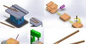
The cuts were made on a stationary circular saw. This produces smooth, burr-free cuts with a width of 2 mm.

Now you need to connect all the pipes into one. The main task is to make smooth curves; for this it will not hurt to use a template (fibreboard sheet) on the table.
Since the pipes are cardboard, they can be connected using PVA glue, but I would recommend using glues that harden stronger and faster (moment, superglue).
On the reverse side, wooden planks were screwed onto self-tapping screws so that the homemade lamp could be hung on the wall. And holes were drilled in each pipe to output wires from the LED strips.

The pipes were painted with regular spray paint. The color red was used, since the wall on which the lamp was to be located was white, I wanted to get some contrast.

The paint dries very quickly, so you can begin installing the LEDs. The main thing to remember is that you can cut the LED strip only in specially marked places. The tape must be marked in advance so that it is enough for all 12 pipes.
We solder red wires to the “+” contact, and black wires to the “-” contact, so as not to confuse the polarity later.

We place the LED strips inside the pipes and fix them with the adhesive side to the pipe wall, and route the wires through pre-made holes. All that remains is to connect all the wires in parallel (connect red to red, and black to black) and connect to the power supply.

Now it's time to hang your homemade lamp on the wall.
The lamp is ready.

With the rising cost of electricity, many are thinking about purchasing LED light sources, which bring significant savings and are excellent substitutes for natural lighting. However, today not many can afford LED lamps, because their cost is still quite high. Therefore, thanks to folk craftsmen, in this article we will look at how you can make a lighting device from LEDs with your own hands.
What is an LED light?
LEDs are semiconductor electronic devices that emit light as a result of the passage of electric current. Appearing 15 years ago, home appliances literally immediately conquered the light source market. Today you can buy LED lamps of any shape, size, power and color. But you can also make them yourself, which even an inexperienced radio amateur can do. The simplest LED devices can operate at a voltage of 3-5 V, i.e. from a regular battery. However, its power is only enough to illuminate a flashlight, so below we will look at how to make more serious designs that allow you to illuminate rooms.
Lighting device
Composition and principle of operation of the lamp
Before we start making an LED lamp with our own hands, let’s look at its design and operating principle.
A diode is a semiconductor device that passes current through a pn junction in only one direction. As a result of the release of energy during the recombination of electrons and holes, photons are emitted with the release of light and thermal energy.
Heat removal in an LED device is an important task when assembling a lamp, because high temperature leads to degradation and failure of the LED. Therefore, the presence of a radiator is a prerequisite when assembling any LED lamp.
The simplest heatsink is an aluminum substrate on which the LEDs are located, however, such heat removal will not be enough if the device is assembled on 3 or more semiconductors. Special metal radiators are installed in such lamps. In indoor appliances it is replaced by the body of the light bulb.
In addition to the radiator, the LED product has a reflector and diffuser, which can replace a metallized reflector, and a lens.
Typically, LEDs are produced as a ready-made assembly, but in order to prevent the bright light of the device from irritating the eyes, a frosted bulb is used to cover the body of the lamp.

Light bulb device
Lamp assembly
The circuit of the simplest lamp operating from a 220 V network consists of two 12 kOhm resistors and two LEDs installed in parallel. The diagram is relevant for an even number of LED devices.
For odd numbers, the circuit must contain a driver that stabilizes the output current and voltage. It is best to purchase a ready-made driver that is matched to the LED device. In addition, you can also make the driver yourself using a rectifier bridge, capacitors and ordinary diodes, which in the assembly convert the mains voltage into a voltage of a given frequency and value. Resistors in such a circuit act as a current limiter.
As can be seen from the above, an LED device can be assembled by anyone who has held a soldering iron at least once in their life and knows how to use the Internet, where many examples of standard and non-standard circuits and solutions for assembling an LED lamp are presented.

Lamp diagram
Luminaires in the housing

LED Strip Light
You can make the simplest lamp yourself using an LED strip, which you just need to attach to any flat surface using double-sided tape. For greater reliability and expanded functionality of the device, it is convenient to place the LED strip in the housing of a non-working fluorescent lamp, the length of which does not exceed 30 cm.
This lamp is installed at a height of no more than 80 cm above a desk, kitchen surface, aquarium, or used for decorative lighting. The light of the lamp is perfectly diffused and does not tire the eyesight.

Application of the lamp
The following types of strips are suitable for the manufacture of LED lamps:
- SMD 3528 (60 (4.8 W); 120 (7.2 W); 240 (16 W) LEDs per linear meter);
- SMD 5050 (30 (7.2 W); 60 (14 W); 120 (25 W).

LED Density
Density and arrangement of LEDs on SMD 3528 and SMD 5050 strips
The optimal choice would be the SMD 5050 LED strip, the parameters of which correspond to the following values:
- radiation angle – 120 degrees;
- supply voltage – 12 V;
- current – 1.2 A/m
The LED strip must be glued to the inside of the case using tape. To work, you can buy a power supply or assemble it yourself using the diagram below. The advantage of a self-assembled power supply is that it is possible to hide it in the lamp housing. Purchased - you will have to “attach” it next to the device. In any case, the assembled structure will look neat and work economically, perfectly illuminating the desktop.

Electrical circuit of the power supply
An important point during installation is high-quality insulation of all conductive parts.
A DIY lamp based on an LED strip is no different in its parameters from the purchased version. Moreover, its cost is significantly lower than the cost of the finished product.
LED lamps on various bases

LED light
An economical version of an LED lamp can be made with your own hands using a burnt-out lamp. To do this, you need to carefully disassemble the burnt out lamp without damaging the base and clean and degrease it.
In the base we place a 100 Ohm protective resistor and two 220 nF capacitors, the operating voltage of which is 400 V, a 10 µF capacitor responsible for the absence of flicker, a rectifier (diode bridge) and LEDs in a ratio of 1 (red) to 3 (white) ). We connect the components of the circuit by soldering and insulate them with mounting adhesive, filling the entire space of the base between the parts of the circuit and securing them.
In addition to a regular lamp, a halogen lamp is used to create an LED lamp with your own hands.
Halogen lamp

Halogen lamp
To assemble a lamp using a halogen lamp, the following components are required:
- assembly diagram, which you can draw up yourself or take from the Internet;
- LEDs;
- non-working halogen lamp;
- quick-drying glue;
- copper wire;
- soldering iron and solder;
- aluminum substrate 0.2 mm thick, which will replace the radiator;
- resistors;
- hole puncher.
Assembly
The assembly process occurs in the following sequence:
- We clean the halogen lamp from all components and putties.
- We take it out of the reflector.
- We prepare a reflector disk on which the LEDs will be located. We glue the disk onto an aluminum backing (a disk template can be found on the Internet) and make holes in it.
- According to the diagram, we place the LEDs on the disk with their legs up, taking into account their polarity. We roll a little glue between them, avoiding getting it on the contacts.
- We solder the LED contacts so that the chain begins with positive polarity (“+”) and ends with negative (“-”).
- The positive contacts are connected to each other by soldering.
- We connect resistors to the negative contacts by soldering and connect their contacts to each other with solder, obtaining negatively charged resistors.
- We also connect the contacts of the resistors to each other and solder copper wires to them. To avoid short circuits, fill the space between the contacts and wires with glue.
- We glue the disk and the halogen reflector together.
- After the glue has polymerized, you can connect a 12 V power source.
Energy saving lamp
After an energy-saving lamp has served its life and burned out, hand-made craftsmen recommend not throwing it away, but using the device to create an LED lighting device. This can be done if the lamp has a working electronic ballast (EB) and a whole housing with a base, which will become the basis of the new product.
To complete the package, you need to purchase 5 mm LEDs and 4 ultra-fast UF4007 diodes.
The essence of creating an LED lamp based on an energy-saving one is to install a rectifier bridge at the output of the EB, which will allow you to obtain a constant voltage of 100 V at a current of 130 mA.
To reduce the frequency of the alternating voltage at the EB output, we will assemble a rectifier bridge from UF4007 diodes, to the output of which we solder a 0.1 μF capacitor operating at a voltage of 400 V. We install the diode bridge in place of capacitor C3 (see typical diagram of an EB lamp) connecting the filaments incandescent lamp, which we then close together.

Electrical circuit of the EB lamp
Separately, we assemble a series circuit of 30 LED devices, the current consumption of which is 20 mA, and check its operation.
At a constant voltage of 100 V and a current of 130 mA, you can assemble 5 chains of LED diodes of 30 pieces each and get a lamp whose power is 15 W.
As we can see from what was described above, you can make an LED lamp yourself, not only by soldering the circuit, but also by using various devices - LED strip and lamps of different types.
 Secrets of choosing halogen chandeliers with remote control