Types of swamps and their characteristics. Subgrade construction in swamps Airfield pavements
Classification of swamps, in relation to pipeline construction
Bogs are diverse in their physical and mechanical properties, which change both over time and in separate sections of the same swamp. This circumstance has long required a clear classification of swamps, especially in engineering work, when peat soils are designed as the foundations of structures.
Designers and builders are interested in the question: how to carry out construction and whether the erected structure will meet all the technical requirements of normal operation.
Therefore, when surveying, designing and operating, it is necessary to clearly know the pressure of the structure on the base, the limits of possible accident-free deformations of the structure and the ability of the peat base to perceive temporary or permanent loads.
A gas pipeline laid underground in swamps, when filling the pipe with peat soil, for stability requires ballasting with weighting loads. Artificially created negative buoyancy presses the gas pipeline to the bottom of the trench. Negative buoyancy per 1 m of the pipe according to SNiP II-45-75 must be at least 5% of the mass of the displaced liquid. It is easy to calculate that the gas pipeline pressure on the peat deposit will not exceed 0.002-0.005 kgf/cm 2 .
If an oil pipeline, an oil product pipeline or a water pipeline with ballasting is laid in a trench, then the pressure on the base will not exceed 0.02-0.06 kgf / cm 2. The pressure from communication cables also does not exceed the specified value. It should be emphasized that the pressure on the base of 0.05-0.06 kgf / cm 2 also occurs in cases where the ballast of the oil product pipeline is calculated from the condition of emptying it during operation. The bearing capacity of peat soil, as a rule, is more than 0.1 kgf / cm 2.
On the other hand, possible settlements of a pipeline laid on a peat base do not cause any significant additional longitudinal stresses, since the pipeline is a flexible thread. The foregoing allows us to draw a conclusion, confirmed by the practice of construction and operation of pipeline crossings through swamps. Bogs completely filled with peat of any degree of decomposition can serve as the basis for steel main pipelines. However, any construction classification of swamps must take into account two main requirements: maintaining the integrity of the structure for the entire period of operation and the method of work.
For the integrity of the structure, it is quite enough that peat soils serve as the basis of the pipeline, completely filling the swamps to the mineral bottom. The second condition requires that swamps be qualified in such a way that, during design and construction, it would be possible to determine the methods of performing work, and during operation, the possibility of access to any transition point.
Since the load from construction equipment on a peat deposit is many times (10-20) greater than from a pipeline, then the classification of swamps should be based on their passability (classification bolt according to Giprospetsgaz).
According to the patency, the swamps are divided into three types:
Type I - swamps completely filled with peat, allowing work and repeated passage of marsh equipment with a specific pressure of 0.2-0.3 kgf / cm 2 or the passage of conventional equipment using shields, roads, ensuring a decrease in specific pressure on the surface of the deposit to 0, 2 kgf / cm 2;
Type II - swamps completely filled with peat, allowing the passage and operation of construction equipment only with the help of shields, roads, providing a decrease in the specific pressure on the surface of the deposit to 0.1 kgf / cm 2; building marshy landscape
Type III - swamps that allow only special equipment to work on pontoons or conventional equipment from floating facilities.
Based on the classification of swamps by passability, prof. P.P. Borodavkin proposes a classification of swamps in relation to main pipelines, taking into account both the passability of marshes by construction equipment, and the length and depth of the peat deposit. Refined classification of swamps prof. P.P. Wartkin is formulated as follows.
- 1. Swamps completely filled with peat of a stable consistency, and areas of swampy soils that allow the work and repeated passage of construction vehicles with a specific pressure on the soil q 0.25 kgf / cm 2;
- 2. Bogs filled with peat of unstable consistency at a depth of peat up to 0.7 m, underlain by dense mineral soil, which allows the operation of conventional construction machines and mechanisms. The width of the swamp along the crossing range is up to 500 m. The bearing capacity of the surface of the swamp is 0.05
- 3. Bogs up to 1.5 m deep on a mineral base, completely filled with peat, allowing the operation and passage of vehicles with a specific pressure on the ground q 0.1 kgf / cm 2. The width of the swamp at the crossing point is up to 250 m.
- 1. Bogs filled with peat of unstable consistency at a depth of peat up to 0.7 m, underlain by mineral soil. Swamp width over 500 m, 0.05
- 2. Bogs completely filled with peat, allowing the operation and passage of vehicles with a specific pressure of up to 0.1 kgf / cm 2. The swamp is up to 1 km wide.
- 1. Swamps that allow the operation of only special floating machines and mechanisms or conventional machines on pontoons;
- 2. Bogs completely filled with peat, allowing the operation and passage of vehicles with a specific pressure of up to 0.1 kgf / cm 2. The swamp is over 1 km wide.
In accordance with the specified division of swamps, it is proposed to classify pipelines laid through swamps as follows.
- excessively moistened land areas with a kind of marsh vegetation and a layer of peat of at least 0.3 m, therefore, they are characterized by a difficult exchange of gases. Marshes usually contain from 87 to 97% water and only 3-13% dry matter (peat).
With a lower peat capacity or its absence, excessively moistened areas are called wetlands.
Swamps are formed when water bodies become overgrown or when the area becomes swampy.
The main way of formation of swamps is swamping, which begins with the appearance of periodic, and then constant waterlogging of soils. The climate contributes to this. Excess moisture due to an abundance of precipitation or low evaporation, as well as a high level of groundwater, the nature of the soil is poorly permeable rocks; "permafrost", relief - flat areas with shallow drainage or depressions with slow flow; prolonged floods on rivers, etc. Forests die under conditions of excess moisture, which means anaerobic conditions and oxygen starvation, which contributes to greater waterlogging due to a decrease in transpiration.
Water-loving vegetation settles on waterlogged lands, adapted to a lack of oxygen and mineral nutrition - moss, etc. Moss sod, which absorbs and retains moisture well, resembling a wet sponge, contributes to even greater waterlogging of the land. So in the future, it is the vegetation that plays the leading role in swamping. In conditions of lack of oxygen, incomplete decomposition of plant residues occurs, which, accumulating, form peat. Therefore, swamping is almost always accompanied by peat accumulation.
The most favorable conditions for the accumulation of peat exist in the forests of the temperate zone, especially in Western Siberia, where, within the forest-bog zone, swampiness sometimes makes up more than 50% of the territory, the peat thickness is 8-10 m. To the north and south of the forest zone, the thickness of the peat deposit decreases: to the north due to a decrease in the growth of plant mass in a cold climate, to the south - due to more intensive decomposition of plant residues in a warm climate. In a hot humid climate, a huge increase in biomass is compensated by an intensive process of decay of dead plants, and there are few swamps, although the evergreen equatorial forests are waterlogged.
The structure of the peat deposits of swamps that have arisen on the site of lakes or dry valleys is different. Peatlands formed as a result of the swamping of lakes have lake silt, sapropel, under a layer of peat, and when the land becomes swamped, peat lies directly on the mineral soil.
Bogs develop in various climatic conditions, but are especially characteristic of the forest zone of the temperate zone and tundra. Their share in Polissya accounts for 28%, in Karelia - about 30%, and in Western Siberia (Vasyugan) - over 50% of the territory. Swampiness sharply decreases in the steppe and forest-steppe zones, where there is less precipitation, and evaporation increases. The total area occupied by swamps is about 2% of the land area of the Earth.
swamp types
According to the nature of the water supply and vegetation, the swamps are divided into three types: lowland, upland and transitional.
lowland swamps are formed on the site of former lakes, in river valleys and in depressions that are permanently or temporarily flooded with water. They feed mainly on groundwater rich in mineral salts. The vegetation cover is dominated by green mosses, various sedges and grasses. Birch, alder, and willow appear on older swamps. These swamps are characterized by weak peat content - the thickness of peat does not exceed 1 — 1 .5 m
Raised bogs are formed on flat watersheds, feed mainly on atmospheric precipitation, the vegetation is characterized by a limited species composition - sphagnum mosses, cotton grass, wild rosemary, cranberry, heather, and woody - pine, birch, less often cedar and larch. The trees are very depressed and stunted. Sphagnum moss grows better in the middle of the marsh massif, on the outskirts it is oppressed by mineralized waters. Therefore, raised bogs are somewhat convex, their middle rises by 3-4 m. The peat layer reaches 6-10 m or more.
transitional swamps, or mixed represent a transitional stage between lowland and upland. In lowland swamps, plant residues accumulate, the surface of the swamp rises. As a result, groundwater rich in salts ceases to feed the swamp. Herbaceous vegetation dies off and is replaced by mosses.
Thus, low-lying bogs turn into raised ones, and the latter are then covered with bushes or meadow vegetation, turning into upland meadows. Therefore, in nature, moss or grass swamps are rarely found in their pure form.
Bogs are of great economic importance. Thus, peat bogs are a source of fuel for industry. The first thermal power plant in the world operating on peat was built in Russia in 1911 (in Elektrougli).
Lowland bog peat is a good organic fertilizer. Therefore, partially lowland swamps are drained and turned into fertile lands. But not all swamps are subject to drainage, some of them must be preserved so as not to disturb the relationships that have developed in nature.
Marshes humidify the air of the area, are the habitats of valuable plant species (cranberries, cloudberries, blueberries) and habitats of many species of animals, especially birds, are natural reservoirs of water that feed the rivers.
STATE PRODUCTION COMMITTEE
FOR TRANSPORT CONSTRUCTION OF THE USSR
Glavtransproekt
"SOYUZDORPROEKT"
INSTRUCTIONS
FOR THE DESIGN OF THE GROUND PLATE
ROADS IN THE SWAMPS
Moscow - 1963
FOREWORD
The Guidelines set out the principles for choosing a design depending on local conditions and the main methods for calculating the subgrade in swamps. In addition, the Guidelines provide the basic requirements for the data of surveys of roads in swamps. The appendix gives examples of designing the main types of subgrade structures in swamps.
When drawing up the Instructions, the relevant regulatory and instructive literature was used, as well as the experience of Soyuzdorproekt accumulated in recent years in designing a subgrade in swamps.
The instructions were compiled by an employee of the Soyuzdorproekt, Candidate of Technical Sciences I.E. Evgeniev.
. GENERAL PROVISIONS
1. These Guidelines are drawn up in the development of existing regulatory documents *) and can be used in the design of the subgrade of roads in swamps in those cases that are not covered by standard solutions.
*) NTU 128-55 (taking into account the changes and additions included in the draft SNiP ch. 37); CH 140-60.
2. The designs and calculation methods proposed by the Guidelines have been developed for peat bogs.
Note: The instructions do not address the issues of subgrade construction in swamps in permafrost conditions.
3. Guidelines are developed in relation to the requirements for the design of roads with improved pavements. For the design of local and temporary roads, only general design recommendations are given.
a) the subgrade must be resistant to bulging deformations or extrusion of weak soil from under the embankment (if this is not provided for by the peat removal technology adopted in the project);
b) before laying the pavement, at least 50% of the consolidation of the base soil must occur, i.e. intensive settlement due to compaction of the base should stop;
Table 1
The main physical and mechanical properties of peat according to the road construction classification
|
Depending on the type of swamp and the category of the road, the design of the subgrade is selected, which has the best technical and economic indicators under the given conditions. In this case, the following constructive solutions are possible: A. Embankments resting on the mineral bottom of the swamp (Artificial grounds) a) pile racks; b) embankments with the complete removal of weak soil from the base and its replacement with high-quality soil; c) mounds sunk onto the mineral bottom of the swamp by squeezing weak soil to the sides. B. Embankments resting on a peat deposit with measures to improve the building properties of a weak base a) Partial excavation; b) subgrade with vertical drains and drainage slots; c) deep compaction of weak soils with soil piles; d) chemical strengthening of weak foundation soils. B. An earth bed laid directly on the surface of a peat deposit a) Floating massive embankments; b) lightweight embankments; c) flooring and slan; d) specially lightweight constructions. Artificial bases should generally only be used where the retention of weak soil under the embankment could cause the subgrade to deform.. 6. Part of the subgrade below the swamp surface is recommended to be made of draining soils. Dusty soils are allowed in the above-water part of the road embankment, provided that the general requirements for ensuring the water-thermal regime of the subgrade and pavement are met. 7. When designing structural elements of the subgrade, you should use the manual "Typical transverse profiles of the subgrade of highways" / vol. 41/ Soyuzdorproekt, taking into account the additions and changes set forth in these Instructions. . Survey Data Required for Subgrade Design8. As part of the work on the survey of roads in swamps, in the part related to the design of the subgrade, the following should be provided for: At the design stage: a) the data needed to select the type of subgrade construction; b) data for drawing up the project of the organization to the cost of work. At the design stage - Data for a specific calculation of the elements of the selected subgrade structure. The survey methodology and program is developed in accordance with the Guidelines for surveying roads in swamps (Soyuzdorproekt, 1959), taking into account the requirements for source materials listed in this chapter. a) the depth of the swamp (bottom topography), b) the type of peats that make up the deposit (geotechnical sections); c) degree of decomposition of peat; d) swamp stumpiness; e) other situational data (forest coverage, availability of roads, reservoirs, populated areas, etc.); f) technical and economic data for calculating the cost of work (range of transportation of mineral soil, the need for temporary roads, etc.). 10. The relief of the bottom of the swamp in the area of the route is determined by sounding and drilling in accordance with the Guidelines for Surveying Roads in the Swamps of 1959. 11. The belonging of peat in the state of natural occurrence to one or another type of road construction classification is determined during field surveys according to the complex of its physical and mechanical properties and external features listed in Table. *). *) the characteristics given in columns 6-8 of the table are recommended to be determined in the field laboratory. The type of deposit can also be determined from observational data on the nature of deformations of the base of existing embankments under similar conditions. 12. In cases where a peat deposit consists of several layers of peat of different types, the type of deposit as a whole is determined depending on the thickness of the weaker layers. If at least 90% of the total thickness of the peat deposit is peat I type - swamp should be attributed to I type; if more than 10% of the total thickness of the deposit is plastic formations II type, - the swamp belongs to II type; if more than 50% of the total thickness of the deposit is fluid layers IIItype, - swamp refers to type III. 13. The stumpiness of the swamp is determined by the percentage of the probe (drill) hitting large undecayed tree remains in relation to the total number of probe immersions. 14. At the stage of the design task, geotechnical sections are drawn up along the axis of the route and cross-sections, where the types and subtypes of peat are distinguished, indicating the thickness and boundaries of the strike of each layer. 15. For the purposes of detailed design, in-depth processing of field survey data and laboratory determination of the physical and mechanical properties of peat that make up the deposit are carried out according to a special program and estimate in accordance with the specific requirements for calculating the selected structure (see table). table 2 The composition of the laboratory tests required for the working design of the subgrade in the swamps
The consolidation coefficient is found according to the graph of the deformation of the sample in time at a constant load, close in value to the specific pressure of the designed embankment on the base soil. In this case, the consolidation ratio is equal to:
Where: h arr- the height of the monolith in the compression device; t- time from the start of loading to the attenuation of intense deformation of the seal. The optimal angle of laying the slopes of the excavation in peat (when peat is excavated) is determined by driving a test pit cvertical walls. If the vertical slope in this layer of peat is retained for at least 3 days, the project provides for vertical walls, otherwise more gentle slopes are designed. The characteristics of subgrade soils are determined by generally accepted methods. III. Selecting the type of subgrade construction according to survey data17. In order to ensure the choice of the most appropriate design of the subgrade, according to surveys at the design stage / see. n. / possible options for subgrade for a given category of road are outlined according to Table. . |
Peat depth, m |
|||||||||||||||||||||||||||||||||||||||||||||||||||||||||||||||||||||||||||||||||||||||||||||||||||||||||||||||||||||||||||||||||||||||||||||
|
I |
II and III |
IV and V |
||||||||||||||||||||||||||||||||||||||||||||||||||||||||||||||||||||||||||||||||||||||||||||||||||||||||||||||||||||||||||||||||||||||||||||
|
1 |
2 |
3 |
4 |
5 |
||||||||||||||||||||||||||||||||||||||||||||||||||||||||||||||||||||||||||||||||||||||||||||||||||||||||||||||||||||||||||||||||||||||||||
|
up to 2 |
Complete peat |
Complete peat |
||||||||||||||||||||||||||||||||||||||||||||||||||||||||||||||||||||||||||||||||||||||||||||||||||||||||||||||||||||||||||||||||||||||||||||
|
Complete peat |
Complete excavation for subtype 1-B or drainage slots /for subtype 1-A/ |
Massive embankment, poured onto the surface of the deposit for subtype 1-A or partial peat removal /for subtype 1-B/ |
||||||||||||||||||||||||||||||||||||||||||||||||||||||||||||||||||||||||||||||||||||||||||||||||||||||||||||||||||||||||||||||||||||||||||||
|
over 4 |
Vertical drains |
Vertical drains |
||||||||||||||||||||||||||||||||||||||||||||||||||||||||||||||||||||||||||||||||||||||||||||||||||||||||||||||||||||||||||||||||||||||||||||
|
up to 2 |
Complete peat |
Complete peat |
||||||||||||||||||||||||||||||||||||||||||||||||||||||||||||||||||||||||||||||||||||||||||||||||||||||||||||||||||||||||||||||||||||||||||||
|
Planting an embankment on the mineral bottom of the bog by extruding peat for subtype II-A - mandatory, with preliminary loosening by explosive or mechanical means |
Embankment planting for min. swamp bottom, vertical drains only for subtype II A |
Lightweight floating embankment of slag and other light materials or soil embankment with brushwood / fashin / lining at the base |
||||||||||||||||||||||||||||||||||||||||||||||||||||||||||||||||||||||||||||||||||||||||||||||||||||||||||||||||||||||||||||||||||||||||||||
|
up to 8 |
Planting an embankment on the mineral bottom of the swamp by squeezing out peat |
|||||||||||||||||||||||||||||||||||||||||||||||||||||||||||||||||||||||||||||||||||||||||||||||||||||||||||||||||||||||||||||||||||||||||||||
|
Over 8 |
Pile overpass |
Accepted in each specific case on the basis of technical and economic calculations |
||||||||||||||||||||||||||||||||||||||||||||||||||||||||||||||||||||||||||||||||||||||||||||||||||||||||||||||||||||||||||||||||||||||||||||
In cases where on the roads IV
category, an improved type of pavement is used, the subgrade of increased solidity should be selected in accordance with the recommendations for roads II - III categories.For the selected subgrade design at the stage of the design assignment, the main parameters necessary for calculating the volume and cost of work are determined approximately according to the instructions given in the chapters -.
a) at the location of existing road embankments, buildings and structures, the basis of which is peat soil, at a distance closer than twice the depth of the deposit;
b) in peat deposits of type I-A, if the peat is covered with a layer of mineral soil or the deposit has mineral layers with a total ratio of the thickness of the overlying mineral layers to the peat thickness of at least 1:2.
Structures with vertical drains and drainage slots should not be used if the stump content of the peat deposit is more than 20%.
Pronounced layering of the reservoir, when the horizontal permeability of the formation is several times higher than the vertical one, contributes to an increase in the efficiency of vertical drainage.
20. In general, floating embankments can only be recommended for low category roads. However, in some cases, in the presence of dense peat /for example, corresponding to the description of paragraph -b/, they can be used as a base for roads of high categories.
21. For roads of low categories, it is expedient to lay at the base of a floating embankment a brushwood lining of a slant made of non-commercial wood, obtained, in particular, when clearing the right of way. Existing experience has shown that the construction of floorings and slates from imported standard materials is not economically justified.
22. With an appropriate feasibility study, it is possible to use special subgrade structures in swamps, which have a frequent area of \u200b\u200bapplication and are therefore not included in Table.:
a) deep compaction of weak soils with sand piles;
b) special lightweight structures made of porous concrete, with cavities, corrugated metal pipes, etc.;
c) chemical strengthening of weak soils;
d) temporary /seasonal/ roads made of precast concrete slabs.
The listed designs are currently experimental and the methodology for their calculation and design is not given in the Instructions.
23. When staged construction is possible, especially in shallow swamps I type, instead of peat or vertical drains, floating massive embankments should be arranged. At the same time, at the first stage /about a year after the construction of the embankment/ a transitional type coating is laid, and after 3-5 years, after the attenuation of the deformation of the base is established by observations, the capital type is laid.
The rate of consolidation of the base of the floating embankment can be increased using the device side longitudinal slots or additional temporary surcharge /see. ch./.
. Design of floating embankments (built directly on the surface of the swamp)
24. The possibility of using floating embankments is limited by the need to comply with the requirements of paragraph. It should be taken into account that the conditions of stability and inadmissibility of significant elastic drawdowns for floatingembankments in some cases, especially in swamps IItypes turn out to be mutually exclusive, because an increase in the height of the embankment can lead to an excess of the bearing capacity of the foundation.
25. The thickness of the bulk layer is determined as the sum of the design height of the embankment above the surrounding surface of the swamp and the amount of settlement along the axial section of the subgrade. The thickness of the bulk layer should be such that the elastic subsidence of the subgrade during traffic does not exceed the permissible value for this type of coating. In table. the approximate values of the minimum thickness of the bulk layer in the swamps are given /without taking into account the structural thickness of the pavement/ according to A.A. Tkachenko:
Table 4
|
Required thickness of the mineral layer depending on the type of clothing |
|||
|
asphalt concrete |
black rubble |
transitional coating |
|
|
8 or more |
|||
If there is a natural layer of mineral soil on the surface of the bog, the required thickness of the fill soil can be reduced by the thickness of the natural mineral layer.
27. In all cases, the height of the embankment above the surface of the swamp /after settlement/ should not be less than recommended by technical standards from the condition of observing the water-thermal regime.
The rate of foundation consolidation can be increased through the following activities:
a) arrangement of vertical drains and drainage slots / see. ch. /;
b) arrangement of deep drainage slots on both sides of the embankment;
c) variable additional load method.
33. With the help of temporary additional surcharge, it is possible to accelerate the consolidation of the base of the embankment in swamps Ilike 7-8 times. It is expedient to use the method of temporary loading if it is possible to reuse the soil of the loading layer. The thickness of the loading layer should be taken at least half the thickness of the permanent bulk layer.
When applying the method of temporary additional surcharge, the uplift stability of the base is subject to mandatory verification / see. P. /.
The calculation of the acceleration of peat consolidation at the base of the embankment with temporary surcharge is carried out by the following steps:
a) in accordance with clause, the amount of settlement is determined from the weight of the embankment with surcharge (S2);
b) in the same way, the magnitude of the settlement of the embankment without surcharge is determined (S1);
c) in accordance with paragraph, the duration of stabilization of the settlement of the base from the embankment with surcharge is determinedt2;
d) the duration of compaction of the base from the weight of the embankment with surcharge to the density that would be achieved by compaction without surcharge is determined by the formula:
. (6)
If it is possible to carry out control during the construction of the road, the surcharge is removed after the calculated settlement of the embankment from the design height is reached (S1).
34. The lower part of the floating embankment should be constructed from draining soils to a height not less than the calculated settlement value. The rest of the embankment is subject to the usual requirements common to all types of subgrade in mounds.
35. Roadside ditches are designed in accordance with the recommendations of the "Album of typical transverse profiles" Soyuzdorproekt vol. 41. If it is impossible to comply with the longitudinal slope of the ditches for the removal of collected water /not less than 0.005/ their installation is not recommended.
. Design of subgrade with complete excavation
36. The method of complete peat removal consists in removing weak soil from the base of the embankment to dense layers of the mineral bottom of the swamp with immediate filling of the excavation with high-quality imported soil. At the same time, it is necessary to comply with the condition that the sole of the embankment rests on the roof of dense layers with its entire area.
37. When designing peat excavation, one should strive for maximum stability of the subgrade by creating the steepest excavation slopes. The slope angle of the excavation is assigned according to the data of field studies /p. 16/. The width of the bottom of the excavation should not be less than the width of the subgrade between the edges of the embankment.
In order to ensure the quality of peat removal, the mark of the bottom of the excavation should be set 10 - 15 cm below the bottom of the swamp.
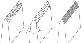
38. If there is a longitudinal or transverse slope of the swamp bottom of more than 10%, the bottom should be developed in steps during mechanical peat removal, or in the case of unstable peat, a large stone should be thrown from the lower side / fig. a, b/.
With the explosive method of peat removal, the sloping bottom should be worked out with chisels / fig. V/.
39. Depending on the type of swamp and the amount of work, peat removal can be carried out in the following ways:
a) mechanical development;
b) ejection explosions;
c) blasting under an embankment;
d) hydraulic peat removal;
e) planting an embankment on the bottom of the swamp with extrusion of weak soil by the weight of the embankment.
Note: For instructions on the technology and organization of peat removal by various methods, see SNiP III-D. 5-62.
40. In the swamps II and III type subgrade, as a rule, should be constructed by squeezing out weak layers by the weight of the embankment being poured. At the same time, the requirement to support the entire sole of the embankment on the dense layers of the mineral bottom of the swamp must also be met.
If there are dense layers of peat in the upper part of the swamp, the latter must be removed or loosened by mechanical, explosive or hydraulic methods to the width of the subgrade plus two strips on each side with a width not less than the depth of the swamp. If dense layers make up more than half the depth of the swamp, to facilitate extrusion, peat inlets should be provided on both sides of the embankment. The volume of peat receivers must be at least half the volume of peat to be squeezed out.
The minimum height of the bulk layer required to extrude a weak layer is determined by the formula:
(7)
Where: IN- the width of the embankment at the base
WITH- adhesion of the weak layer
N sl- power of the extruded layer
Volumetric weight of the embankment soil.
. Design of subgrade with partial excavation
41. An earth bed with partial peat should be assigned in the following cases:
a) if the density of the peat deposit increases with depth;
b) if at a certain depth of the swamp there is a layer of high stumpiness, which does not allow the use of other types of subgrade structures;
c) in order to accelerate the consolidation of the base.
The same requirements apply to a subgrade with partial peat removal as to floating embankments / Ch. /.
42. The minimum depth of replacement of peat with high-quality mineral soil should be such that the total thickness of the bulk layer from the top of the remaining peat layer to the design mark is not less than that required by Table. .
43. The stability of the base of the embankment against extrusion with partial peat should be checked according to the Gersevanov-Puzyrevsky formula:
45. The duration of the intensive settlement of the embankment due to the consolidation of the foundation soils is determined in the same way as for the floating embankment / p. 82/.
With partial peat removal, the base consolidation rate increases in proportion to the square of the ratio of the total depth of the swamp to the thickness of the removed peat.
VII. Subgrade with vertical drains and drainage slots
46. Vertical drainage of the subgrade base is carried out in order to accelerate the consolidation of base soils, increase their stability and reduce elastic settlements.
The acceleration of the consolidation of the base by vertical drains or drainage slots occurs due to a significant reduction in the filtration path of water squeezed out of the soil mass during compaction by the weight of the embankment. Vertical drains make it possible to accelerate settlement tenfold compared to a floating embankment.
Vertical drains or drainage slots quickly relieve the pressure that occurs in the pores of water-saturated soil after the application of an external load. Therefore, the shear resistance of the base with drains increases much faster than without drainage /almost - as the embankment is filled/.
Vertical drains or drainage slots change the overall elasticity of the bog soil mass, so the elastic subsidence on the subgrade surface with vertical drains is about 3 times lower than without drains.
47. With a swamp depth of up to 3 m, it is recommended to design the subgrade with drainage slots, the installation of which does not require special equipment /the slots are torn off by an excavator/. Drainage slots may be arranged only in peatlands capable of holding vertical slopes for the time required to fill the trench with sand.
Vertical drains can be used at a swamp depth of more than 2 m, with a deposit thickness of more than 8-10 m, it may be appropriate to use partially submerged drains. However, it should be borne in mind that with incomplete immersion of drains, the period of consolidation of the base increases significantly.
Vertical drains can be used in peat Itype in compacted bog soils of type II-A.
48. Drains and slots should be filled with coarse or medium sand with a filtration coefficient of at least 3 m/day. The lower part of the embankment, to a thickness not less than the expected settlement, should also be filled from sandy soils with a water permeability of at least 3 m / day.
49. The thickness of the bulk layer over peat with vertical drains or drainage slots from the conditions of requirements for reducing elastic deformations can be equal to half the value required according to Table. but not less than 2.5 m.
50. Settlement of a road embankment on peat with vertical drains is determined by the formula:
Swamp I type A
Swamp I type B
Peat II type A sapropels at humidity below the yield point
53. The distance between the slots based on the settlement stabilization period is 4-6 months. with a slot width of 0.7 m, a deposit depth of 1.5 to 3 m, the following can be approximately accepted:
swamp I type A - 2.4 m
I type B - 2.0 m
II type A - 1.8 m
54. Approximately assigned distance between vertical drains should be checked and specified according to laboratory data. The calculation is made according to the nomogram shown in fig. .
Rice. 1. Scheme of options for preparing a peat excavation pit with an inclined swamp bottom.
Rice. 2. Nomogram for calculation of foundations with vertical drains.
If, as a result of the check, it turns out that the degree of consolidation of the base for a given time / with approximately selected parameters of the subgrade construction / is less than 90%, the distance between the drains should be reduced.
If there is a compacted layer of peat or cohesive soil on the surface of the swamp, take into account vertical filtration in the calculations /U in/ do not do it.
An example of a consolidation calculation of vertical drains is given in the Appendix..
To calculate, you need to know:
deposit depth - N T(m)
peat consolidation coefficient during filtration in the vertical direction - From to(m 2 / day)
peat consolidation coefficient during filtration in the horizontal direction - C g(m 2 / day)
approximately accepted distance between drains -l(m)
set time 90% consolidation -t(days)
tentatively accepted ratio of the distance between the drains to their diameter - P.
Having calculated , on the right scale 5 is determinedU in% for a given timet .Further, on scale 1 there is a point corresponding to the calculated value , from which through a point on scale 2 corresponding to the value P, a straight line is drawn up to scale 3. The point of intersection will give the valueU g. Overall degree of consolidationU totalis on scale 4 at the point of intersection of the direct connecting valueU g on scale 3 and U in on scale 5.
55. Checking the correctness of the assigned distance between the drainage slots is carried out according to the schedule in fig. .
To calculate the subgrade with drainage slots, you need to know: the coefficient of consolidation of weak soil - WITH, deposit depth - H, the given consolidation time ist. According to the schedule, it is determined what degree of consolidation of the foundation soil will be achieved over time t - at the appointed distance between the slots -l. See the Appendix for an example calculation.
For the sake of simplicity, the consolidation ratio is assumed to be the same for both vertical and horizontal exfiltration.
If, with the specified design parameters, the degree of base consolidation at a given time is less than 90%, the distance between the slots should be reduced.
Design characteristics
Symbol
I layer
II layer
average value
1. Type of peat
I-A
I-A
2. Layer thickness /m/
H
3. The coefficient of porosity in eat. able
e 0
4. Porosity ratio after compaction
e p =0.5
5. Consolidation ratio /m 2 /day/
WITH
0,0105
0,0074
0,0095
6. The height of the bulk layer
H n
7. Volumetric weight of peat t / m 3
1,02
1,01
1,02
8. Volumetric weight of the fill material
The calculated data given in the table are determined during field or laboratory surveys, with the exception of the value of the porosity coefficient of peat after compaction by the load, which is equivalent to the specific pressure of the embankment on the base -e p
The value of the specific pressure on the base:
t/m 2 = 0,5 kg / cm 2.
If there is a groundwater horizon near the surface, the pressure of the overlying peat layers on the underlying ones can be neglected, because the volumetric weight of peat is close to unity.
The porosity coefficient of peat in the state of compaction is determined by the results of compression tests under load R= 0.5 kg/cm 2 for each layer.
In accordance with the table. of these Instructions, on peat deposits Itype under the improved type coating, it is recommended to arrange a subgrade with vertical drains;
The need for vertical drains can also be verified by calculation. If the design of the subgrade of the "floating embankment" type is adopted, then the duration of the settlement is calculated by the formula / /:
where: the average consolidation ratio is:
Therefore, the requirement to achieve 90% consolidation of the base of the subgrade in this case will be met only 8 years after the construction of the embankment. In order to ensure the possibility of laying clothes in the same year in which the subgrade was erected, the period of consolidation should not exceed 6 months. Significant reduction in consolidation time can be achieved with vertical drains.
Tentatively, the design parameters of the subgrade with vertical drains can be assigned according to Table. instructions. For peat deposit type I-A at power H= 6 m distance between drains is recommended - 2.4 m.
The diameter of the drains is assigned taking into account the available equipment - in this case, it is acceptedd=0.35 m. Then the ratio of the distance between the drains to their diameter
![]() .
.
Knowing the coefficient of consolidation of the peat deposit - From Wed, you can check the correctness of the assigned distance between the drains according to the nomogram / fig. /.
1. Determination of the degree of consolidation of the base without drains for a given period /t=6 months/.
The value is calculated
![]() .
.
Scale 5 determines the degree of consolidation with vertical filtrationU in =19 %.
2. Determination of the degree of consolidation of the base from the impact of vertical drains.
Computed
![]() .
.
Through the corresponding point on the scale 2 P\u003d 6.1 a straight line is drawn to scale 3, where the value is obtainedU g=86 %.
3. Determination of the general degree of consolidation of the base with vertical drains.
But the second part of the nomogram is a point on scale 3, corresponding to the valueU in\u003d 86%, connect with a point on the scale 5 corresponding to the valueU in =19 %.
On scale 9 we get the desired valueU total=90 %.
In this case, it turned out that the pre-selected design parameters meet the specified requirements.
It should be noted that the calculation by nomograms can also be carried out in the opposite way, looking for the required period of consolidation or the required distance between drains according to the given general parameters.-A has a thickness of 2.7 m. The peat that makes up the deposit has the following design characteristics:
1. Porosity ratio in natural statee 0= 8.6 m.
2. Porosity ratio after compaction by the weight of the embankmente p=6,2.
3. Consolidation ratio C p\u003d 0.0105 m 2 / kg. The peat layer is underlain by dense loams. The total height of the bulk layer is assigned from the condition of compliance with the allowable elastic deformations /p. 53/h n=2.5 m.
Volumetric weight of the embankment material - =2 t/m 3 . The value of the specific pressure at the base of the embankment, at which thee p is:
In accordance with the table. of these Guidelines, on peat deposits of type I-And for improved paved roads, a subgrade with drainage slots is recommended.
The ratio of the distance between the slots to the depth:
The value of the “time factor”, plotted along the abscissa of the graph, in this case will be equal to:
![]() .
.
(In order to ensure the completion of construction in one season, the time of 90% consolidation is assumedt=180 days)
The thickness of the peat layer left under the embankment is determined based on compliance with the requirement to achieve 90% consolidation in 180 days according to the formula / /:
8 /:
 .
.
Where for this example:
Bulk weight of peat \u003d 1.02 t / m 3
Peat depthh vyt=1.2 m.
Peat grip WITH\u003d 1.2 t / m 2
Angle of internal frictionj=8° /in radians j=0,14/
4.4 t / m 2 less than the allowable calculation P without=5.4 t/m 2 , so the stability of the designed structure can be considered secured.
1. Types and characteristics of swamps
Swamp - excessively moist areas of the earth's surface, on which most of the year there is water.
Wetlands- these are areas where surface water stagnates or is systematically waterlogged, but peat cover does not form or has a thickness of less than 30 cm.
According to the condition of location and water supply, they distinguish: upland and downstream swamps.
Raised swamps- formed during the stagnation of precipitation in watershed areas with small slopes. Raised bogs consist of peat throughout their thickness. In the final stage of its formation, the middle of the bog (consisting of peat and sphagnum (moss)) can rise 6-8 meters above the banks.
Lowland swamps- formed as a result of overgrowth of reservoirs. Waterlogging begins from the coast to the middle. The dying remains of vegetation raise the bottom of the swamp, thereby forming silt deposits. In the final stage of the formation of a grassroots swamp, it forms on the surface of the quagmire. The alloy consists of rhizomes and mosses. An alloy with a thickness of 3-4 meters is able to withstand a load of 35 MPa.
2. Engineering classification of swamps.
According to SNIP 2.05. 02 -85 distinguish 3 types of swamps:
Bogs filled with bog soils, the strength of which in the natural state makes it possible to erect an embankment up to 3 meters high without the process of lateral extrusion of the soil.
|
Characteristics |
Type of marsh soil |
||
|
Soils included in the type |
Organic silts, mineralized peat mineralized |
Silt and peaty soil |
|
|
Structure |
Spongy fibrous structure, high structural cohesion |
Low fiber, crushed, gel-like structure |
amorphous structure |
|
The predominant type of deformation under embankments |
Compaction within the load contour |
Squeezing the soil to the side |
lateral bulging of weak soil with immersion of the embankment on the mineral bottom of the swamp |
3. Choice of plan for the route of the road in wetlands (basic requirements).
Wetlands are mainly located in the flat areas of the forest zone. When solving the plan of the route in the swampy area, bypass or cross the swamp? In terms of the cost of building a road in wetlands, the cost exceeds 5-6 times compared to a similar section in non-wetlands. The selection is based on TPP.
The main provisions in the design of the route plan.
1-Swamps should be bypassed, unless this is due to a large elongation or tortuosity of the route.
2 - Strive to cross the swamps in the shortest direction, in the narrowest places with a high occurrence of the mineral bottom.
3 - It is desirable to avoid places with curved slopes of the mineral bottom. (sliding embankment)
4 - When crossing, give preference to the type I section. 5 - Variant tracing and variant design of the RFP, must be justified by a feasibility study (FEC)
4. Structural solutions for subgrade in swamps (with complete peat removal, partial peat removal, without peat removal)
Design solutions, but the designs of the PP are selected on the basis of TPP options, taking into account the following, positions: 1) road category. 2) DO type. 3) the required embankment height and the quality of soil available for embankment filling. 4) the length of the section on soft ground. 5) type and properties of soft soil. 6) conditions for the performance of work, including the deadline for completion of construction.
ZP in the swamps of the projects. in the form of an embankment, the requirement for soils in the upper part of the embankment as well as min. elevation of the BS bottom above the vegetation level of the surface and groundwater. It is determined according to SNIP 2.05.02-85. 3rd type of terrain in terms of moisture.
There are a number of requirements for the PO:
1. The possibility of squeezing out the weak soil of the embankment under the base of the embankment during its construction and operation should be excluded. (base must be stable)
2. The intensive part of the settlement of the embankment must be completed before the installation of the coating DO (to ensure stability)
3. Elastic fluctuations of the ZP, arising in the presence of peat soils at the base of the embankment, should not exceed the permissible values.
The following design solutions are allowed
1) Mounds resting on the mineral bottom of the swamp (or artificial foundation).
A. Embankments with complete removal of weak soil and its replacement with high-quality draining soil.
B. Mounds immersed on the mineral bottom of the swamp by squeezing weak soil to the sides.
IN. Overpass construction.
2) Embankments based on peat layers, with measures to improve the building properties of soft soil ():
A. partial peat
B. ZP with vertical drains or drainage slots
IN. Deep compaction of weak soils, soil piles
G. Chemical reinforcement of weak base soils
3) An earthen bed laid directly on the surface of a swamp.
A. Massive floating embankments.
B. Lightweight embankments.
IN. Embankments using wooden layers, spec. lightweight structures.
The part of the subgrade, located below the surface of the swamp, is arranged from draining soils. Dusty soils are allowed in the above-water part of the subgrade. Subject to compliance with the requirements for ensuring the water-thermal regime of the subgrade.
5. Survey of swamps, survey stages.
1) Route options are outlined on cartographic material.
2) Carry out survey work on site, for detailed research and collection of necessary information.
3) A topographic survey of the swamp plan is being carried out
4) Collect samples of soft soils for evaluation of physical and mechanical properties. properties.
5) On the plan of the swamp, a grid of wells is planned for sampling peat . Grid of wells from the axis 50-150 m
6) Sounded drilling is carried out along the grid to a depth of at least 0.5 m. with a step of 50 m.
7) Produce static drilling, the results of which give an idea of the thickness of the weak layers.