Do-it-yourself gate actuator drawings. Digest for amateur craftsmen: how to make automatic gates with your own hands
Owners of sliding gates do not experience any particular difficulties in self-equipping the sash with a drive mechanism, but when it comes to swing gates, much more effort and knowledge is needed. Today we will talk about drives for swing gate leaves and their assembly with our own hands.
There are three main types of gearboxes that convert the rotation of an electric motor into a high torque translational motion. The design of the mechanism can be performed:
- in the form of a gear;
- using a screw stud;
- using rack and pinion.

On these three types of kinematics, it is quite possible to assemble your own mechanism even at home.
The design of the self-made actuator proposed below is not afraid of moisture and pollution, it exerts a very high force when moving.
Please note that with the gate closed, such a home-made drive acts as a lock: it cannot be opened from the outside by pressing on the gate leaf.
Preparing the gate and fixing points
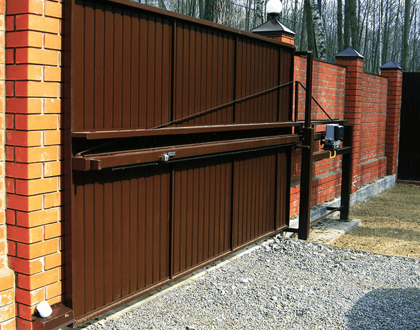
Almost any swing gate or door can be equipped with a drive, but it is better to plan the installation of the mechanics in advance. This applies to the installation of reliable fasteners for the drive. They have the form of metal plates with holes at the ends, one of which is attached strictly perpendicular to the sash, the other is located on a pole or fence in the same position.

When installing the plates, they must be oriented in a horizontal plane and be at the same level. It is very important to take into account the high pulling force of the drive, so the best way to attach the plate to the gate is by welding. Plates can be fixed to stone and brick pillars with metal anchors, but it is much better to make embedded steel elements at the construction stage.
The easiest way is to mount the drive on gates that open inward so that all actuators are located in a protected area. A cable must be laid in the gate opening, so lay a 32 mm plastic pipe under the pavement beforehand.

At the stage of mounting the mounts, you will determine the first basic parameters of your drive. Measure the distance between the centers of the holes in the fasteners when the door is closed and when it is open. The last value is the length of your drive in the folded position, and the difference between the measured distances is the amount of travel of the device.
You can also measure the opening and closing force of the gate with a manual spring balance. Pull the gate leaf fastener in the direction of the opposite fastener, this will help you to select the motor power most accurately.
Production of a drive from car window regulators
Light gate leaves can really be set in motion by a drive from modified window lift mechanisms. The advantage of this method is its relative simplicity and almost silent operation of the drive. The disadvantage is the limited traction force, which is due to the small working stroke of the mechanism.
There are two types of power window designs suitable for use as a gate drive:
- the role of the moving element is played by a gear rack;
- based on gears.

In both cases, the drive part is mounted on a metal platform that is rigidly attached to a pole or fence. In this case, the metal rail should move parallel to the plane of the gate and move forward in their direction.
The lifter mechanism needs to be improved: installation of an elongated metal rod for the rack or a knee lever for the gear wheel. The connections of the rod with the drive and the gate, as well as the two parts of the knee lever, must be made in the form of a fork hinge, following the example of a door closer.

You can ensure good mobility and no backlash if you make one side of the connection in the form of two folded plates, the gap between which is equal to their thickness. The plate of the second part of the hinge will enter this gap. Both elements are connected with a pin or bolt with a self-locking nut.
The main difficulty in the use of power windows is to find the most advantageous position of the drive, the hinge and the place where the rod is attached to the gate. You can confidently do this experimentally by first setting the gate in the open position and, slowly closing it, monitor the behavior of the drive structure. Do not forget that after installation, the mechanism needs a protective cover.
Selection and calculation of engines
As a motion activator for swing gates, it is advisable to use geared motors of various types. If we are talking about small gates of low mass, the motors of cordless screwdrivers, drives of car windshield wipers, power windows, etc. will cope with the task. Another question is how you plan to make a clutch for the shafts of such motors.

You can also choose the right unit from a wide range of shop gearmotors, this gives you more freedom in determining the desired torque. So, let's say the measured closing force of a heavy gate leaf was 13.5 kg on the scale of a manual canter. Each kilogram corresponds to 9.8 N, which means that the traction force is 132.3 N. In the case of a rack or gear drive, this value must be divided by the diameter of the drive wheel, this will be equal to the engine torque.
In the “nut-screw” design, reduction occurs, so an additional recalculation is required. Let's say an M18 stud with a thread pitch of 2.5 mm is selected. This means that for one revolution around a circle with a diameter of 18 mm, the nut makes 2.5 mm of translational movement, so the gear ratio is 7.2:1. Accordingly, if we divide the gate opening force by the gear ratio, we get the desired value of the force on the motor shaft: 132.3 / 7.2 ~ 18.4 N or slightly less than 1.9 kilograms with a stud radius of 0.9 cm. That is, a table the torque value for the engine will be 1.69 kg/cm.

This is a rather rough calculation that does not take into account the friction force in the screw drive and other losses, but it helps to determine the minimum allowable motor power. To compensate for energy losses, it is recommended to provide a power reserve of 100-250%.
It is also necessary to calculate the speed of rotation of the shaft. To do this, divide the stroke length by the thread pitch of the screw drive and you will get the number of revolutions required to fully open the gate. When using a rack and pinion, the calculation is determined by the ratio of the number of teeth of the rack and the drive gear.
Stud for homemade drive
Heavy gates need a drive with a high applied force. Such work is within the power of factory-made drives, but you can create an analogue with your own hands.
The main difficulty is to find a suitable hairpin. Standard drive studs are not suitable: they are made of soft metal, so the thread becomes unusable over time. The way out of the situation is to independently increase the hardness of the metal and the number of contacting threads of the screw gear.
Increasing the hardness of the pin
The first problem is solved by hardening. The required heating temperature is given by ordinary charcoal, it also partially carburizes the metal. Fold the hearth of bricks and cast-iron grates, heat the fuel until the coals burn out completely. Hardening temperature - 700-800 ° C, which corresponds to the rich red color of the metal. Exposure at this temperature is 13-15 minutes, after which the part must be cooled in used oil. The stud must be fully and simultaneously immersed along its entire length, so open the steel pipe along the longitudinal seam, plug the ends and use this tray as a quench bath. The hairpin needs to be slightly shaken in the oil during the entire cooling time, then removed and laid again on the coals without wiping, in order to release the metal. Now the heating must be done up to 200-250 degrees, until the metal turns gray with a pronounced formation of scale. After 3-4 minutes of exposure, the product must be cooled in water.

Enlargement of stud threads
To make a special nut, you need to screw 2-3 standard nuts onto the stud tightly, but without tightening. Align the edges of the nuts and clamp the assembly in a vise very firmly. Weld the nuts together along all edges and grind the product with an angle grinder to the previous dimensions.
Instead of a complicated hardening procedure, you can spend time looking for rolling studs and nuts for them. Such a metal has all the necessary characteristics. In addition, you can choose a thread with a trapezoidal profile: it is much stronger. You can also find a product with a larger thread pitch, which will reduce the operating time of the mechanism.

Assembly of the actuator
Actuator Sizing
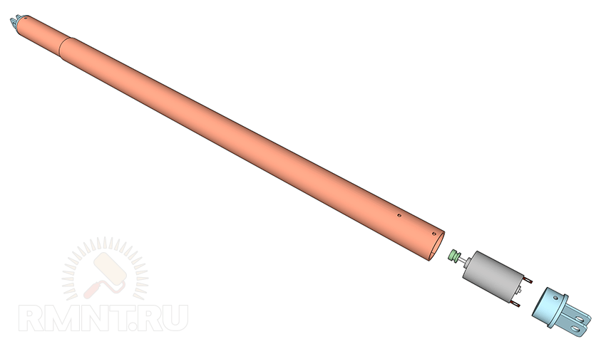
The actuator has a telescopic device, for its manufacture you will need two steel pipes, one of which fits into the other without a strong backlash. You can use a square or round pipe, there is not much difference. Inside both pipes there should be no traces of rust and scale, so it's better to get new ones.

As for the dimensions of the pipes and studs, you must calculate them yourself, based on the measurements taken. Let's say the actuator is 110 cm long when folded and its stroke is 50 cm. This means that the length of the outer tube will be no more than 100 cm, a smaller tube 80 cm long will be inserted into it, and the length of the hairpin will be a full 110 cm or more, depending on the method of mounting the motor. In this case, in the open state, the drive pipes will have an overlap of 30 cm.
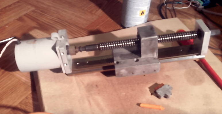
Assembling the drawer
Pass a stud with a nut screwed onto it through the smaller pipe and position its center on the longitudinal axis of the pipe. To ensure centering of the stud, do not select too large diameter pipe. For example, if you are using an M18 nut with a spanner of 27 mm, select a pipe with a nominal diameter of 25 mm. You just have to grind the nut evenly so that it fits snugly into the pipe. Perform fastening by welding. It is not necessary to weld on the inside, but you can do this by cutting a “window” in the pipe. When the nut is fixed, unscrew the stud from it.

At the end of the stud, a radial-axial bearing with a cage closed on both sides must be fixed. The outer diameter of the bearing should be approximately equal to the inner diameter of the pipe. The bearing must slide inside the pipe without significant resistance, the gap between it and the wall must not exceed 1 mm. If the bearing is too tight, carefully sand the end of the outer race with sandpaper. On the stud, the bearing must be firmly clamped between two nuts. Between them and the bearing, be sure to lay 1-2 washers on both sides so that nothing interferes with the rotation. Lubricate the stud liberally with lithol and insert it from the free side of the small pipe, then screw it into the welded nut. Carry out several trial runs along the entire length: the bearing should slide freely inside and not wedged.

End caps and swivel joints
Next up is the stub. It must be made from a metal blank, the diameter of which is slightly smaller than the diameter of the pipe. To make the drive repairable, make two or three holes with a countersink in the pipe, cut the threads for the mounting screws in the corresponding places on the plug. Weld two steel strips with a through hole to the end of the cork so that the gap between them is slightly larger than the thickness of the fastening on the gate leaf. Take into account the distance "stolen" by the plug when calculating the total length of the actuator in the stowed position. Before installing the plug, push 50-70 grams of lithol into the pipe, then tighten the pin so that the bearing enters the pipe by 5 centimeters, add lubricant again and plug the pipe.

Actuator Outer Tube
The stud must be completely unscrewed from the pipe until the bearing rests against the nut. Then the inner tube is inserted into the outer one, and the pin is screwed in 5-6 turns.
Next, you need to decide on the method of mounting the motor. Ideally, the cylindrical motor housing should be fixed inside the pipe with clamping screws. If you were unable to select a motor of suitable dimensions, weld a piece of pipe of a larger diameter, a steel strip or a metal angle to the rear end. So you can fix the oversized engine in any convenient way.
Important: the distance from the surface of the site to the central axis of the pipe must be equal to the height of the motor shaft. Position it in such a way that it is aligned with the hairpin as coaxially as possible.
Motor installation and final assembly
Connect the motor shaft to the stud using a coupling. You can purchase it from the arsenal of components for the motor or make it yourself from two small tubes nested one inside the other. Lubricate the stud a second time and secure the engine to the site. Then, by rotating the inner tube, shorten the length of your actuator to the standard open position. Lubricate the entire surface of the inner tube with lithol and fold the actuator completely.
If you will mount the motor inside the pipe, sink it 5-6 cm deep and use a plug similar to the first one. Pass the motor power wire through the hole made in the bottom of the pipe so that water does not flow inside. Or make a hole in the plug itself. In both cases, it will be reasonable to install gland entries.
If the engine is mounted on the site, weld the fork tip to it, make sure that the structure is sufficiently rigid and protect the engine with a casing. Now you just have to install the actuators in place by connecting the fork ends of the plugs to the mounts on the gates and poles. This can be done with a cotter pin or bolt with a self-locking nut.

Wiring diagram
Equipment selection
The engine is controlled according to the classic reverse scheme, but there is one detail. It is clear that there is a restrictive bar on the swing gates, so the leaves must be folded in a certain order. When torn off, the sash without a bar starts moving first, but it should close last. This can be implemented in different ways, the most reliable is a relay with a turn-on delay.
The assembly of modular devices includes:
- four contactors Hager ES424 (DC24V 4NO);
- two time relays Hager EZN001;
- differential machine Hager AD906J;
- MeanWell DR-120-12 power supply.

The equipment is assembled in a Hager VECTOR VE118DN plastic box with an IP 65 degree of protection. The circuit is designed to power two powerful IG-90GM geared motors at 24 V.
Through the differential machine, power is supplied to the L and N terminals of the power supply. From its reverse side, two 24 V DC lines are removed, each feeding two paired contactors: the input terminals of one of them are powered in reverse polarity. The outputs of the pairs of contactors are connected in parallel and supply voltage to the gearmotors.
Secondary circuits and automation
The contactor control circuit operates at a constant voltage of 24 V. The positive power wire passes through the break contacts of the stop buttons and is connected to the break contacts of the control buttons, from which power is supplied to the normally open contacts of the opposite buttons. From each button, voltage is supplied to two pairs of starters, while one of the normally open contacts performs the function of picking up the coil. The control circuit of the direct starter of the first pair and the reverse starter of the second pair is opened by a normally open relay. Power is supplied to the relay from the normally open contact of the starter of another group. Thus, a time delay is made for the sequential movement of the leaves.
Automatic stop of the motors is carried out by actuation of the end reed switches. They need to be installed along the direction of movement of the actuator, and small neodymium magnets should be glued to the surface of the inner pipes. Thus, when the actuator is fully folded or its stem is extended, the reed switches actuate, which close the power circuit of the intermediate relay with a normally closed contact. The relay is connected in parallel and duplicates the "Stop" button.
Such a drive can also operate under the control of automation for swing gates, the schemes are similar. Now you can open swing gates without leaving your car easily and without serious financial investments.
“A craftsman and a needleworker brings joy to himself and to people.” Don't know what else to do in the yard, if everything has already been redone, and your hands itch? We can suggest an idea. Gates that open and close automatically. Comfort lovers have long appreciated the very idea of remote gate control, and other motorists envy them, especially at a time when it is pouring rain outside. It is clear that most people have to open the gate leaves on their own, but doing this in bad weather is an extremely unpleasant task, and besides, not everyone wants to flop in wet clothes on the seat and get it dirty. Below we will tell you how to make an automatic gate for a garage or a fence with your own hands, providing detailed instructions with photo and video examples.
What are the mechanisms
Nowadays, there are several types of street gates:
- swing;
- retractable;
- roller shutter.
Swing is a classic look. The gate consists of two leaves, mounted on pivoting hinges to a vertical base, deeply and firmly installed steel frame. For manual or automatic opening of the sashes, space in front of them is required.
If you want to make automatic swing gates for a summer house with your own hands, we recommend watching this video:
Homemade sliding mechanism
Retractable on rollers, usually this is one leaf, technically simple design, since the weight of the gate is distributed on the rollers, and additional reinforced guides are installed to withstand wind and lateral loads. Such mechanisms have some features in operation, but at the same time, it is enough just to make the mechanical part for them with your own hands.
If you are interested in this option of automatic fence gates, we recommend that you watch this video review:
Homemade retractable mechanism
sliding gate idea
Roller-type garage doors are a set of rails made of metal and plastic, linked together by a movable lock, placed in guide grooves and connected into one single structure. Moving along the metal guides, the segments are bent, located under the ceiling and freeing the entrance to the garage.

Lift-and-turn garage doors perform a complex maneuver, going up and freeing the passage. The automatic lifting mechanism for them is difficult to install and operate, so we will not consider it within the framework of this article.
Operating principle
The mechanism for opening swing gates is a set of two motors and an automation system that monitors the position of the leaves and the sequence of their opening / closing, and also captures and recognizes commands from the remote control. A leaf with an overlay profile-groove should start moving first when the gate automatically opens and finish moving last when closing, in order to avoid jamming and damage to the leaves. Also, the movement should stop at the extreme points of the position of the valves. The power of the motors directly depends on the weight of the wings and the smoothness of their movement - the heavier, the more powerful the engine and gearbox are needed to control them. It is also worth considering the area of \u200b\u200bthe canvas, the effect of wind on them. On a windy day it is much harder for the motors to move the gate. It is better to provide for and make an emergency opening of the street gate, in the event of a breakdown or lack of electricity, in manual mode.
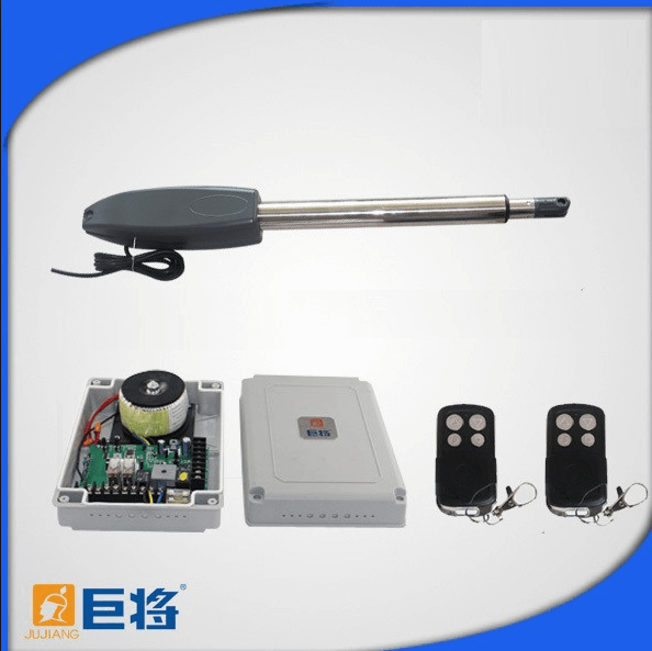
Both in factory and home-made drives, they mainly use an actuator or a linear drive, which is shown in the photo below:
It is a threaded stud that is connected to the engine and rotates on bearings. Due to the rotation of the stud, the counterpart, the coupling, is wound along the thread, thereby moving along the stud. This drive design is also sometimes called a worm drive.
The reduction factor depends on the thread pitch, the smaller the pitch, the greater the force the actuator can transmit, but the speed in this case decreases. As an electric motor, you can use the motor reducer of car wipers or power windows.
The mechanism of automatic sliding gates is quite simple to implement. One motor, one gearbox. The transmission of linear motion can be on a rack with teeth, or through a motorcycle chain. Automation monitors the extreme positions of the sash, closed or open. The main highlight is the rigid design of the sash and the system of rollers that hold this design during closing and opening. It also provides resistance to side load during wind. The main task is to make sure that the balanced sash moves easily and effortlessly along the rollers and guides. During the development of the gate, it is necessary to provide for emergency opening in the event of a breakdown or power outage. As email. drive it is also possible to use the engine from the power window or wipers.

Garage automatic gates, in turn, are also divided into roller shutter (they can also be called sectional) and up-and-over. This type is problematic to do on your own due to the complexity of the production technology. Their advantage is that the production takes place on an individual order in the workshop, and the installation is carried out as a whole block, so it does not take much time.
Outcome
Now on the market there is a wide range of mechanisms and elements in order to be able to make automatic gates with remote opening and closing from the remote control.
In our article, we tried to acquaint readers with the existing types of mechanisms and suggest an idea for self-assembly or choosing the appropriate option for automatic gates for a country house, pointing out the points that need to be paid closer attention, namely.
The main convenience of automatic swing gates is that you can close or open them using the remote control. Everyone today wants to make their life as comfortable as possible. That is why the owners of private houses or their own garages are increasingly finding automation for you to mount it quite quickly, while getting an excellent result.
System Features
It is worth understanding how the whole system works. Automation of the gate is possible by means of a drive, which is mounted directly on the gate. A gate automation kit is not difficult to mount with your own hands. The installation process is not that easy. Here it is required to follow a clear sequence of actions in combination with accuracy and qualification at each stage of work. When installing the drive, there are several features. It is necessary to take into account the sash in relation to the height of the pillars. If the installed automation does not imply the presence of limit switches, then it is required to install leaf stops. If you miss such an important nuance, you can get a completely unexpected result. The electric motor will fail, and the functioning of the entire structure can hardly be called normal.
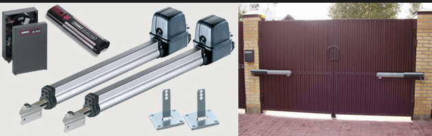
Equipment
Many elements contain such a complex as automation for swing gates. It will be possible to mount it with your own hands only if all the components are present. For the correct and high-quality installation of the gate, you need to understand this and have minimal experience in solving such issues. The automation kit contains: 1 2 drives, 1 set of photocells, a small beacon and a remote control. The advantages of this type of mechanism include a long service life and exceptional strength. in operation, and the gate opens at a speed of up to 15 seconds. Among the shortcomings, one can single out such a moment as the presence of at least one obstacle in the path of the gate, because of which the drive may well fail, and this leads to jamming. There should not be any obstacles in front of the opening. Only in this case, it can be expected that do-it-yourself automation for swing gates will function for a long time without failing. Carrying out preventive measures will prevent equipment failures. All parts that require it must be periodically lubricated with special substances. If the automation fails, it is strictly forbidden to exert physical effort if necessary to open the gate, there is only one solution - to call the master.

homemade drive
As you could already understand, with a great desire, automation for swing gates with your own hands is no longer such an unrealistic idea. This is a pretty good way to save your own money. If you have not only practical interest in this case, but you are interested in the realization of the idea itself, then this case is just for you. And it's quite an exciting process.
Required Items
The mechanism of a satellite dish is used as the main element of such a drive. Its set of equipment includes a worm gear that replaces the electric drive. The basis of the satellite television system consists of a rotary action mechanism. This is an engine that can be used to install automation. The worm gear works on a principle similar to that of an electric drive. This option is more profitable in comparison with store drives, since it requires a voltage of 36 volts for its operation, and for store drives it requires a regular network of 220 volts. For assembly, you need to get two working drives from satellite dishes. It is worth choosing models with the longest stem. You will also need a remote control and a transformer, its power should be 36-40 watts. The remote control is used to open the structure and close it. It should work at a distance of about 50 meters. In addition, it would not hurt to stock up on two key fobs sold in stores that sell goods needed in the field of security.
6 hours will be enough to collect the drive. In order for the gate automation to work efficiently with your own hands, you need to equip it with a current relay. Without it, the motor may overheat and break down. And with its help, you can easily make a drive for the gate with the most minimal cash investment. If you like the finished assembly more, then you can save on installation.

Mounting process
When installing an electric drive for swing gates, it is necessary to take into account the direction of opening of the gate leaves: outward or inward. So, if you are interested in how do-it-yourself gate automation is installed, then here you need to list the necessary tools for these purposes. You will need: drill, hammer, pliers, building meter, screwdriver, electrical tape. In automatic gates, unlike conventional ones, there is an electric drive. Therefore, before installing it, you need to decide which option to choose.
Types of electric drives
Electric drives can be linear or lever. To accurately determine the choice, you need to know the distance between the loop and the inside of the post. For distances up to 1.5 cm, a linear drive is required. Its cost is noticeably lower than that of the lever. If the measured distance is 1.5-3 cm, then it is appropriate to install a lever type drive. It is as reliable as linear.
The gate assumes that it is required to install not only the drive, but also a set of equipment. It is important to determine the width of the sash, as well as possible wind vibrations. Many people are afraid to install all this equipment on their own, as they do not have the necessary experience and knowledge. But here it is important to remember the need for attention to detail, then there will be no problems with the installation.

How it's done?
It is important to check that the leaf movement is easy when the drive is started. If something interferes with this, then it is necessary to find the cause and eliminate it, since the movement of the electric drive must be level. Otherwise, it is possible that the post may tilt, the angle of movement will shift, and this has a bad effect on the automation of the entire structure. After fixing various problems, you can proceed to the process of installing automation. It is important to follow the instructions as accurately as possible so that the operation of the system is as long as possible.
Regular circuit
Do-it-yourself automation for swing gates is installed on products that open inwards, while it is appropriate to use any electric drive. When using steel poles as a base, it is appropriate to install a linear drive. It is compact and reliable, and its cost is relatively low. You can also use a lever drive, but it is much more expensive. A difficult option in the presence of brick columns and finding the gate right in the middle. In this case, the linear drive is not suitable.
Lever-type automation is mounted on a pole, while the gates are opened by levers, while they must be at a distance of no more than 200 mm from the poles.

Gates open out
In this case, two types of devices are available for use, however, an automatic garage door with a linear mechanism will be the right choice. This is a cheaper and better solution. Automation is mounted in the opening, and occupies no more than 150 mm on both sides. On narrow gates, the system is attached at the top. The actuator is usually mounted directly on the pole. Do-it-yourself automation for swing gates is installed so that the hydraulic drive allows you to open them outward. Next, the fastener bracket is welded to the structure. When opening a gate with a linear drive, there must be 1 cm of free play. After that, you can check the correct movement of the leaves and the movement of the electric drives. The next step is to install the stops for opening and closing, and then attach the motors. At the end, you need to equip the jumpers, connect to the consoles, and also turn on the mechanism. If one leaf is to move in a different direction, then the wires on the motor must be reversed.

Final work
After that, do-it-yourself automation for swing gates must be equipped with limit switches. If you have not provided for the use of such elements, then you need to set the operating time of the sash on the board, as well as the opening and closing force. You should not set the maximum force, as this reduces the device. It is recommended to set the minimum force so that the door opens normally outward.

Problems and bugs
Quite often there are cases when people mount everything with their own hands, but do not cope with this task due to insufficient experience. This leads to a lot of errors, due to which the automation refuses to work, and the drive completely fails. Everything should be connected in stages, since this is what will correct any problems in case of mistakes. Otherwise, it will be very problematic to establish the cause of the breakdown. Proper and accurate installation, together with the high quality of the electric drive, allows the gate to function as long and correctly as possible. Even if you use automation for sliding gates, you will quickly be able to assess how convenient it has become for you to drive in. This is especially noticeable in winter, when you do not want to leave the warm interior of your car to open the cold gate.
To protect the entrance area in the territory for various purposes, sliding gates can be used, which operate using special automation. In this case, there are also certain installation features. Automation for retractable is installed in stages. First you need to weld a steel cantilever pipe to their structure from below. During the operation of the entire structure, it moves along roller carts installed on a specially organized foundation. Came gate automation has proven itself well. In the closed position, the lower corner of the gate is rolled up by the end roller into the trap. During the opening of the web, this movement helps to prevent lateral vibrations of the device.
Automation for sliding gates should be mounted taking into account certain points:
The installation of such structures begins with the arrangement of an independent foundation, as well as the foundation located in the opening and to the side of it, in the direction of opening the entire structure;
The gate fastenings and their frame itself must be characterized by a high degree of resistance to winds;
It requires the installation of a special holding part, through which it is possible to increase the width of the leaf structure in the direction in which the gate opens;
It must be provided with effective protection against hacking, as well as a special type of protection against various adverse factors.
conclusions
Now you know how do-it-yourself swing gate automation is mounted. If you have a strong desire, you must strictly follow the instructions in order to get the desired result. It is important to note that automation for sectional doors is installed according to a similar principle. Therefore, you should not have any difficulties with the installation process.
We will talk about drives for swing gates and their assembly with our own hands
Owners of sliding gates do not experience any particular difficulties in self-equipping the sash with a drive mechanism, but when it comes to swing gates, much more effort and knowledge is needed. Today we will talk about drives for swing gate leaves and their assembly with our own hands.
There are three main types of gearboxes that convert the rotation of an electric motor into a high torque translational motion. The design of the mechanism can be performed:
- in the form of a gear;
- using a screw stud;
- using rack and pinion.
On these three types of kinematics, it is quite possible to assemble your own mechanism even at home.
The design of the self-made actuator proposed below is not afraid of moisture and pollution, it exerts a very high force when moving.
Please note that with the gate closed, such a home-made drive acts as a lock: it cannot be opened from the outside by pressing on the gate leaf.
Preparing the gate and fixing points
Almost any swing gate or door can be equipped with a drive, but it is better to plan the installation of the mechanics in advance. This applies to the installation of reliable fasteners for the drive. They have the form of metal plates with holes at the ends, one of which is attached strictly perpendicular to the sash, the other is located on a pole or fence in the same position.
When installing the plates, they must be oriented in a horizontal plane and be at the same level. It is very important to take into account the high pulling force of the drive, so the best way to attach the plate to the gate is by welding. Plates can be fixed to stone and brick pillars with metal anchors, but it is much better to make embedded steel elements at the construction stage.
The easiest way is to mount the drive on gates that open inward so that all actuators are located in a protected area. A cable must be laid in the gate opening, so lay a 32 mm plastic pipe under the pavement beforehand.
At the stage of mounting the mounts, you will determine the first basic parameters of your drive. Measure the distance between the centers of the holes in the fasteners when the door is closed and when it is open. The last value is the length of your drive in the folded position, and the difference between the measured distances is the amount of travel of the device.
You can also measure the opening and closing force of the gate with a manual spring balance. Pull the gate leaf fastener in the direction of the opposite fastener, this will help you to select the motor power most accurately.
Production of a drive from car window regulators
Light gate leaves can really be set in motion by a drive from modified window lift mechanisms. The advantage of this method is its relative simplicity and almost silent operation of the drive. The disadvantage is the limited traction force, which is due to the small working stroke of the mechanism.
There are two types of power window designs suitable for use as a gate drive:
- the role of the moving element is played by a gear rack;
- based on gears.
In both cases, the drive part is mounted on a metal platform that is rigidly attached to a pole or fence. In this case, the metal rail should move parallel to the plane of the gate and move forward in their direction.
The lifter mechanism needs to be improved: installation of an elongated metal rod for the rack or a knee lever for the gear wheel. The connections of the rod with the drive and the gate, as well as the two parts of the knee lever, must be made in the form of a fork hinge, following the example of a door closer.
You can ensure good mobility and no backlash if you make one side of the connection in the form of two folded plates, the gap between which is equal to their thickness. The plate of the second part of the hinge will enter this gap. Both elements are connected with a pin or bolt with a self-locking nut.
The main difficulty in the use of power windows is to find the most advantageous position of the drive, the hinge and the place where the rod is attached to the gate. You can confidently do this experimentally by first setting the gate in the open position and, slowly closing it, monitor the behavior of the drive structure. Do not forget that after installation, the mechanism needs a protective cover.
Selection and calculation of engines
As a motion activator for swing gates, it is advisable to use geared motors of various types. If we are talking about small gates of low mass, the motors of cordless screwdrivers, drives of car windshield wipers, power windows, etc. will cope with the task. Another question is how you plan to make a clutch for the shafts of such motors.
You can also choose the right unit from a wide range of shop gearmotors, this gives you more freedom in determining the desired torque. So, let's say the measured closing force of a heavy gate leaf was 13.5 kg on the scale of a manual canter. Each kilogram corresponds to 9.8 N, which means that the traction force is 132.3 N. In the case of a rack or gear drive, this value must be divided by the diameter of the drive wheel, this will be equal to the engine torque.
In the “nut-screw” design, reduction occurs, so an additional recalculation is required. Let's say an M18 stud with a thread pitch of 2.5 mm is selected. This means that for one revolution around a circle with a diameter of 18 mm, the nut makes 2.5 mm of translational movement, so the gear ratio is 7.2:1. Accordingly, if we divide the gate opening force by the gear ratio, we get the desired value of the force on the motor shaft: 132.3 / 7.2 ~ 18.4 N or slightly less than 1.9 kilograms with a stud radius of 0.9 cm. That is, a table the torque value for the engine will be 1.69 kg/cm.
This is a rather rough calculation that does not take into account the friction force in the screw drive and other losses, but it helps to determine the minimum allowable motor power. To compensate for energy losses, it is recommended to provide a power reserve of 100–250%.
It is also necessary to calculate the speed of rotation of the shaft. To do this, divide the stroke length by the thread pitch of the screw drive and you will get the number of revolutions required to fully open the gate. When using a rack and pinion, the calculation is determined by the ratio of the number of teeth of the rack and the drive gear.
Stud for homemade drive
Heavy gates need a drive with a high applied force. Such work is within the power of factory-made drives, but you can create an analogue with your own hands.
The main difficulty is finding a suitable hairpin. Standard drive studs are not suitable: they are made of soft metal, so the thread becomes unusable over time. The way out of the situation is to independently increase the hardness of the metal and the number of contacting threads of the screw gear.
Increasing the hardness of the pin
The first problem is solved by hardening. The required heating temperature is given by ordinary charcoal, it also partially carburizes the metal. Fold the hearth of bricks and cast-iron grates, heat the fuel until the coals burn out completely. The hardening temperature is 700–800 °C, which corresponds to the rich red color of the metal. Exposure at this temperature is 13–15 minutes, after which the part must be cooled in used oil. The stud must be fully and simultaneously immersed along its entire length, so open the steel pipe along the longitudinal seam, plug the ends and use this tray as a quench bath. The hairpin needs to be slightly shaken in the oil during the entire cooling time, then removed and laid again on the coals without wiping, in order to release the metal. Now heating must be performed up to 200-250 degrees, until the metal turns gray with a pronounced formation of scale. After 3-4 minutes of exposure, the product must be cooled in water.
Enlargement of stud threads
To make a special nut, you need to screw 2-3 standard nuts onto the stud tightly, but without tightening. Align the edges of the nuts and clamp the assembly in a vise very firmly. Weld the nuts together along all edges and grind the product with an angle grinder to the previous dimensions.
Instead of a complicated hardening procedure, you can spend time looking for rolling studs and nuts for them. Such a metal has all the necessary characteristics. In addition, you can choose a thread with a trapezoidal profile: it is much stronger. You can also find a product with a larger thread pitch, which will reduce the operating time of the mechanism.
Assembly of the actuator
Actuator Sizing
The actuator has a telescopic device, for its manufacture you will need two steel pipes, one of which fits into the other without a strong backlash. You can use a square or round pipe, there is not much difference. Inside both pipes there should be no traces of rust and scale, so it's better to get new ones.
As for the dimensions of the pipes and studs, you must calculate them yourself, based on the measurements taken. Let's say the actuator is 110 cm long when folded and its stroke is 50 cm. This means that the length of the outer tube will be no more than 100 cm, a smaller tube 80 cm long will be inserted into it, and the length of the hairpin will be a full 110 cm or more, depending on the method of mounting the motor. In this case, in the open state, the drive pipes will have an overlap of 30 cm.
Assembling the drawer
Pass a stud with a nut screwed onto it through the smaller pipe and position its center on the longitudinal axis of the pipe. To ensure centering of the stud, do not select too large diameter pipe. For example, if you are using an M18 nut with a spanner of 27 mm, select a pipe with a nominal diameter of 25 mm. You just have to grind the nut evenly so that it fits snugly into the pipe. Perform fastening by welding. It is not necessary to weld on the inside, but you can do this by cutting a “window” in the pipe. When the nut is fixed, unscrew the stud from it.
At the end of the stud, a radial-axial bearing with a cage closed on both sides must be fixed. The outer diameter of the bearing should be approximately equal to the inner diameter of the pipe. The bearing must slide inside the pipe without significant resistance, the gap between it and the wall must not exceed 1 mm. If the bearing is too tight, carefully sand the end of the outer race with sandpaper. On the stud, the bearing must be firmly clamped between two nuts. Between them and the bearing, be sure to lay 1-2 washers on both sides so that nothing interferes with the rotation. Lubricate the stud liberally with lithol and insert it from the free side of the small pipe, then screw it into the welded nut. Carry out several trial runs along the entire length: the bearing should slide freely inside and not wedged.
End caps and swivel joints
Next up is the stub. It must be made from a metal blank, the diameter of which is slightly smaller than the diameter of the pipe. To make the drive repairable, make two or three holes with a countersink in the pipe, cut the threads for the mounting screws in the corresponding places on the plug. Weld two steel strips with a through hole to the end of the cork so that the gap between them is slightly larger than the thickness of the fastening on the gate leaf. Take into account the distance "stolen" by the plug when calculating the total length of the actuator in the stowed position. Before installing the plug, push 50–70 grams of lithol into the pipe, then tighten the pin so that the bearing enters the pipe by 5 centimeters, add grease again and plug the pipe.
Actuator Outer Tube
The stud must be completely unscrewed from the pipe until the bearing rests against the nut. Then the inner tube is inserted into the outer one, and the pin is screwed in 5-6 turns.
Next, you need to decide on the method of mounting the motor. Ideally, the cylindrical motor housing should be fixed inside the pipe with clamping screws. If you were unable to select a motor of suitable dimensions, weld a piece of pipe of a larger diameter, a steel strip or a metal angle to the rear end. So you can fix the oversized engine in any convenient way.
Important: the distance from the surface of the site to the central axis of the pipe must be equal to the height of the motor shaft. Position it in such a way that it is aligned with the hairpin as coaxially as possible.
Motor installation and final assembly
Connect the motor shaft to the stud using a coupling. You can purchase it from the arsenal of components for the motor or make it yourself from two small tubes nested one inside the other. Lubricate the stud a second time and secure the engine to the site. Then, by rotating the inner tube, shorten the length of your actuator to the standard open position. Lubricate the entire surface of the inner tube with lithol and fold the actuator completely.
If you will mount the motor inside the pipe, sink it 5-6 cm deep and use a plug similar to the first one. Pass the motor power wire through the hole made in the bottom of the pipe so that water does not flow inside. Or make a hole in the plug itself. In both cases, it will be reasonable to install gland entries.
If the engine is mounted on the site, weld the fork tip to it, make sure that the structure is sufficiently rigid and protect the engine with a casing. Now you just have to install the actuators in place by connecting the fork ends of the plugs to the mounts on the gates and poles. This can be done with a cotter pin or bolt with a self-locking nut.
Wiring diagram
Equipment selection
The engine is controlled according to the classic reverse scheme, but there is one detail. It is clear that there is a restrictive bar on the swing gates, so the leaves must be folded in a certain order. When torn off, the sash without a bar starts moving first, but it should close last. This can be implemented in different ways, the most reliable is a relay with a turn-on delay.
The assembly of modular devices includes:
- four contactors Hager ES424 (DC24V 4NO);
- two time relays Hager EZN001;
- differential machine Hager AD906J;
- MeanWell DR-120–12 power supply.
The equipment is assembled in a Hager VECTOR VE118DN plastic box with an IP 65 degree of protection. The circuit is designed to power two powerful IG-90GM geared motors at 24 V.
Through the differential machine, power is supplied to the L and N terminals of the power supply. From its reverse side, two 24 V DC lines are removed, each feeding two paired contactors: the input terminals of one of them are powered in reverse polarity. The outputs of the pairs of contactors are connected in parallel and supply voltage to the gearmotors.
Secondary circuits and automation
The contactor control circuit operates at a constant voltage of 24 V. The positive power wire passes through the break contacts of the stop buttons and is connected to the break contacts of the control buttons, from which power is supplied to the normally open contacts of the opposite buttons. From each button, voltage is supplied to two pairs of starters, while one of the normally open contacts performs the function of picking up the coil. The control circuit of the direct starter of the first pair and the reverse starter of the second pair is opened by a normally open relay. Power is supplied to the relay from the normally open contact of the starter of another group. Thus, a time delay is made for the sequential movement of the leaves.
Automatic stop of the motors is carried out by actuation of the end reed switches. They need to be installed along the direction of movement of the actuator, and small neodymium magnets should be glued to the surface of the inner pipes. Thus, when the actuator is fully folded or its stem is extended, the reed switches actuate, which close the power circuit of the intermediate relay with a normally closed contact. The relay is connected in parallel and duplicates the "Stop" button.
Such a drive can also operate under the control of automation for swing gates, the schemes are similar. Now you can open swing gates without leaving your car easily and without serious financial investments. published
Swing. In this article we will tell you how to make swing gates with your own hands, consider the example of manufacturing metal and automatic gates, give explanatory photos, diagrams and drawings.
Regardless of the chosen design, you reserve the right to choose the method of opening them - inside the yard or outside. Making swing gates is not difficult. The classic form of swing gates has a number of distinctive features:
- Functionality.
- Ease of use.
- Compactness.
- Lack of beams and guide rollers.
- There are no size restrictions.
- The ability to use different materials for manufacturing.
- The ability to use all sorts of details for decoration.
Types of metal structures

Before proceeding with the manufacture of gates, it is important to determine their design. The choice depends on the frequency of their use. Several types of gates can be made from metal, we will consider each separately.

This type of construction is not so popular. They are one continuous sheet. In order for them to function well, the support pole should be securely strengthened, which will require a lot of money. If such gates are installed on a garage, then it is necessary to build a powerful metal frame and reinforced hinges. Moreover, the disadvantage is that it is necessary to organize enough space for opening single-leaf swing gates.

The most common and convenient type of swing gates. Without any effort, they can be made at home. Moreover, their design includes two identical canvases. Therefore, a frame is made of two frames, sheathed with sheet material. Unlike the previous design, less free space is required to open.

For daily use, such gates are very convenient. Moreover, they are made according to the same principle as conventional double-leaf gates. The only difference is that in the right place on one of the wings you fix an additional beam and a support for installing the gate. If gates of such a plan are mounted on a garage, then a mortise type of gate is used. In this case, the desired hole is cut out in one of the gate leaves and the door is installed.
Forged swing gates are made more for aesthetic effect. If the structure is made in the form of closed elements, then decorative forging is used, but an open type of gate is often used.
As for the garage, a closed type of gate with separate forging elements is used for their construction.
Regardless of the type of construction, garage doors can be insulated. Due to this, heat in the garage will be preserved. And your car, at the same time, will not corrode due to sudden temperature fluctuations.

By following the guide below, you will be able to make metal swing gates with your own hands. But for this it is important to closely adhere to the drawing / diagram of the design you have chosen. If it is difficult for you to design your own swing gate drawing, then at the end of the article, you will find many schemes that can be taken as a basis. The basis of the gate will be a metal frame, the fastening of which is carried out in the entrance opening. If you decide to make a gate in your yard, then you can immediately design a gate with a built-in gate. But for this you will need to install strong poles that can withstand the weight of additional doors. You also need to install supports, for this you will need:
- building level and tape measure;
- metal pipe 3 pcs. Ø 100 mm;
- shovel;
- facing brick (in case the supports are lined);
- cement, sand, gravel and water;
- plumb.
Installation of supports
The work on the manufacture of supports is as follows:
- Measure the entrance opening between the edges of the fence.
- Put marks for the installation of poles.
- In the chosen place, dig a hole for the installation of a support column.
- The thickness of the support pipes is selected based on the weight of the swing gate.
- Having installed the posts in the pit, adjust them according to the level. But first fill the bottom of the pit with rubble.
- The installed pillars should be poured with prepared concrete.
- In order for the pillars to initially stand securely, they should be lined with bricks in the hole itself, and at the same time adjust the vertical level.
- Thus, the installation and concreting of the supporting pillars is completed.
If the gate has a height of 2 m, then the depth of the pit should be about 1 m, and in diameter 100 mm wider than the diameter of the pipe.
Now is the time to start making the gate frame. For this you will need:
- metal sheet, 2-3 mm thick;
- metal profile, corner and pipe;
- measuring instruments (level, tape measure);
- metal loops;
- welding machine.
If you are making swing gates for a garage, then first of all you need to make a frame and install it in the opening. It is made from a metal corner of a rectangular or square shape, depending on the opening of the garage.
As for the manufacture of a frame for a garage, it is better to make them in duplicate. Fix one on the outside of the opening, and the second on the inside. Between themselves, they are connected by metal strips and welding.

The manufacturing process of gate leaves is as follows:
- Lay out corners or a profile pipe on a flat surface and weld the shape of the sash according to the drawing.
- To increase the strength of the structure, the resulting sashes are reinforced with diagonal beams.
- When the frame is ready, you can sheathe it.
- For sheathing the gate, use a sheet of metal 2 mm thick. It is not recommended to take sheets that are too thick, because in this case it will be necessary to strengthen the support posts.
- Next, you need to install the hinges. Weld one half of the hinge in the right place on the gate frame, and the other on the support post.
- In conclusion, it remains to install a mortise lock and a gate made according to the same principle as the main frame.
- Painting swing gates is carried out on the ground or already in a suspended position. There is no particular difference. The only thing to consider is painting in limbo can cause streaks and sagging. Therefore, be careful when performing this work process.

Every person has a desire for comfort. And this applies even to the use of the gate. Modern technologies have made it possible to automate the process of opening swing gates. And this has many advantages. For example, when you are in a hurry, you should not waste time getting out of your car to open/close the shutters. If it's raining outside, you'll avoid getting wet by going outside again. Reflecting on these positive aspects, we suggest that you consider the manufacturing technology and some features of automatic gates.

First, let's highlight some of the features of such a structure:
- Strength.
- Versatility.
- Long service life.
- The mechanism is unpretentious and simple.
- The opening/closing speed is around 15 s.
For the sake of objectivity, consider the disadvantages:
- If during the opening / closing of the gate leaves there is an obstacle on the way, this will disable the automation, and the leaves will jam.
- It is necessary to regularly check the opening path of the gate, otherwise a breakdown is inevitable.
In addition, it is worth highlighting the frequent breakdowns of automation. Although manufacturers claim that this or that mechanism is extremely reliable, nothing is eternal. However, by carrying out preventive work, any troubles can be avoided.
If during operation the automation stops working, then you should not close the gate by force. It may be necessary to turn the process from opening to closing. When pressed again, the mechanism can work.
Although not in all cases this solves the problem. Often you have to contact specialists for automatic repair. Given all this, do not be afraid of such a design. As the saying goes: "to be afraid of a wolf - do not go into the forest." Do not give up the benefits of comfort.

It should be noted right away that the procedure for installing automatic gates is quite laborious. It requires some skill, precision and accuracy. Therefore, if you doubt your abilities, it is better to choose a company that will do everything efficiently and quickly. If you have experience in such work, then following the guide, you will be able to achieve the intended goal.
The manufacturing process of swing gates has been described above. Therefore, we will pay special attention to automation, which is equipped in accordance with certain standards.
So, when installing automation, you must consider the following indicators:
- the position of the wings relative to the support column;
- if the automation is used without the use of limit switches, then a leaf stop is used.
Without taking into account these important factors, the automation will fail, which will lead to a rupture of the bracket, a breakdown of the electric motor and other unpleasant consequences.

With a strong desire, automation for opening the gate can be done independently. Especially for amateurs - this business will become a real hobby. This is especially true for those people who want to save money.
In any case, the basis of such a drive will be a mechanism that is installed on the gate from a satellite dish. It, in turn, is equipped with a worm gear. As a result, it will completely replace a conventional electric drive.

The system for satellite television in its design has a rotary action mechanism (this applies to old-type systems). This mechanism is an electric motor that can be used for installation on swing gates. As for the worm gear, its principle of operation is similar to the drive. But as for the first option (worm gear), it is more profitable, since a voltage of 36V is sufficient for its operation, conventional store drives require a voltage of 220V.
Speaking from the safety side, the use of such a step-down transformer plan is more profitable. Moreover, if the voltage increases, then the opening / closing of the gate leaves increases. However, with prolonged increased voltage, the mechanism may fail.

So, to assemble home-made automation, take 2 drives in working order from a satellite dish. Give advantages to those that have long stems.
This mechanism can be purchased at a relatively low price in a specialized company. Plus, you will need to buy a remote control and a transformer, a power of 36–40V.
The remote control will act as a signal to the electric drive to open / close the gate through the leaf. This system can also be installed on garage doors. The range of the remote control can reach up to 50 m. The entire drive is assembled within 6 hours. In order for all automation to work properly, supplement it with a current relay. It will prevent possible damage in case a stone or other object gets under the gate leaf. Automation will return the sashes back. If the relay is absent, then after several times the motor may burn out, and the door leaf may become unusable.
This is how you can independently make automation for swing gates. If you do not have the opportunity and desire to do all this, then you can buy the mechanism already ready.

First of all, you should consider the method of opening swing gates. For example, the flaps can open inwards or outwards. Based on this, you should choose the appropriate automation. Immediately before installation, prepare the following material and tools:
- hammer;
- insulating tape;
- roulette;
- screwdriver;
- pliers;
- drill.
An appropriate electric drive is also selected. It is of two types:
- Linear.
- Lever.
How to determine which one you need? If the internal distance between the support posts is up to 1.5 m, then a linear one is required. In this case, the automation will not have levers, and, accordingly, take up less space on the gate. If the distance is more than 1.5 m and reaches up to 3 m, then a lever mechanism should be purchased. This drive is also unpretentious, just designed for heavy loads. Among other things, you should select the necessary components. For this, the wind load must be taken into account.
During installation, make sure the doors open freely. It is very important to keep track of this, since after installing the electric drive it may be too late to configure anything.
If you find that the movement of the valves is difficult, then determine the problem and immediately fix it. One of the possible problems is the movement of the valves is not level. The reason for this is the inclined pillar of the support. As a consequence, this has a negative effect on automation. When all the shortcomings are eliminated, then you can proceed with the installation of automation on the gate.
If you bought the gate automation in a store, then closely follow the manufacturer's instructions when installing it. In this case, it will work properly for a long time.

It is believed that opening the gate into the courtyard is a standard scheme. Therefore, any drive will be suitable for this project. So, if the support posts are made of steel, then it is preferable to use a linear drive. It is a completely different matter if you have brick supports, and swing gates are located in the center of the column. In this case, the linear drive is not suitable. You will have to install and buy a lever electric drive. The automation itself is mounted on poles, and the levers will allow you to open swing gates, even if the distance from the pole to the leaf is 200 mm.

Compared to each other, both linear and lever are suitable for external opening of the gate. But starting from the price, preference, of course, falls on a linear electric drive. The only thing to consider is the method of attaching the drive to the pole when opening from the outside.
In most cases, the drive is attached to a brick, which can quickly crumble. Worse if the drive is mounted to an almost destroyed pole. Under such conditions, automation will disappear with part of the pillar.

Given this, such a pillar requires additional reinforcement. For example, a metal frame can be welded around. Further, the drive, opening outward, is set to manual mode, the mounting brackets are attached to the gate by welding. In the event that you use a linear drive, then after welding, open the gate completely and leave a free play of up to 1 m. After that, check the movement of the leaf and the correct operation of the drive. If everything works properly, then you can connect the automation and connect the engine.
All automation and remote control is configured according to the attached instructions. If one of the wings opens in the wrong direction, then it is enough to shift the wire in the connection. But if you follow the connection diagram, then no problems should arise.

So, it is important to make the right choice of the necessary automation, considering which way the swing gate leaves will open. From this article, you learned that it is possible to make automation yourself. An easier option is to purchase a ready-made kit. But one thing is known, regardless of the choice you make, having automatic gates will make your life easier. Therefore, when building a gate in a country house, think about which method will be used from opening - automatic or manual. If you have your own experience in arranging automatic gates, then write comments on this article.
Video
In the provided video material, it is described in more detail about the manufacture of swing gates:
Photo
The photographs show the possible options for swing gates:


Schemes and drawings
The diagrams will help you design your own model of swing gates: