Homemade cnc laser engraver made of stones and sticks. Do-it-yourself plotter Necessary materials and tools
In this article, we will tell you how to make a do-it-yourself plotter. As a result, you will get an intelligent and inexpensive mini cnc plotter on arduino, made with your own hands with a writing arm. Most of the parts are 3D printed, but even if you don't have them, you can still make a plotter yourself - you just need to find the right parts. Nema motors or working stepper motors from printers can be used as a motor.
The main advantage of the presented plotter is its frame, which gives a very compact look. The electronics are simple: this plotter is controlled by the Arduino Nano microcontroller. You will also need an IC driver (commonly used in LED lamp designs).
Such a plotter, of course, will not replace the original device in terms of processing quality, but a do-it-yourself cutting plotter is quite suitable for performing some tasks in a home workshop.
You can also experiment with different types of drawing machines, including a drum plotter, a V-cut plotter, and a roller drawing robot. It would be more correct to say drawing, because instead of a cutter, this plotter uses an ordinary pencil. Using such a device, you can draw postcards, posters, drawings, diagrams, etc.
CNC PLOTTER OWN HANDS
Remember that a DIY CNC plotter cannot replace the original one. With this device, you can draw simple images, so the assembly of such a plotter should be taken as an experiment. Video with a step-by-step creation of an arduino plotter with your own hands:
Even if you are a beginner, try to make your own CNC plotter yourself, as it will help you quickly get used to the world of CNC.
Translated by DARXTON.
Plotters are devices that automatically draw drawings, drawings, diagrams on paper, fabric, leather and other materials with a given accuracy. Models of equipment with a cutting function are widespread. Making a plotter with your own hands at home is quite possible. This will require parts from an old printer or dvd drive, certain software and some other materials.
Making a small plotter from a dvd drive yourself is relatively easy. Such a device on arduino will cost much less than its branded counterpart.
The working area of the created device will be 4 by 4 cm.
To work you will need the following materials:
- glue or double-sided tape;
- solder for soldering;
- wires for installing jumpers;
- dvd drive (2 pcs.), from which the stepper motor is taken;
- Arduino uno;
- servo motor;
- microcircuit L293D (driver that controls motors) - 2 pcs.;
- solderless breadboard (plastic base with a set of conductive connectors).
To bring the conceived project to life, you should collect such tools:
- soldering iron;
- screwdriver;
- mini drill.
Experienced lovers of electronic homemade products can use additional parts to assemble a more functional device.
Assembly stages
The assembly of the cnc plotter is carried out according to the following algorithm:
- using a screwdriver, 2 dvd drives are disassembled (the result is shown in the photo below) and stepper motors are taken out of them, while two side bases are selected from the remaining parts for the future plotter;
Disassembled DVD drive
- the selected bases are connected with screws (having previously adjusted them in size), while obtaining the X and Y axes, as in the photo below;

X-Y axes in an assembly
- the X-axis is attached to the Z-axis, which is servo with holder for a pencil or pen, as shown in the photo;

- attach to the Y-axis a 5 by 5 cm square made of plywood (or plastic, boards), which will serve as the basis for the stacked paper;
Base for placing the paper
- collect, paying special attention to the connection of stepper motors, an electrical circuit on a solderless board according to the diagram below;

Wiring diagram
- enter a code to test the performance of the X-Y axes;
- check the functioning of the homemade product: if the stepper motors are working, then the parts are connected according to the diagram correctly;
- load the working code into a CNC-made plotter (for Arduino);
- download and run the exe program to work with the G-code;
- install the Inkscape program (vector graphics editor) on the computer;
- install an add-on to it, which allows converting the G-code into images;
- customize Inkscape work.
After that, the homemade mini-plotter is ready to work.
Some nuances of work
The coordinate axes must be located perpendicular to each other. In this case, the pencil (or pen), fixed in the holder, should move up and down with the servo without any problems. If the stepper drives do not work, then you need to check the correctness of their connection with the L293D microcircuits and find a working option.
Code for testing the X-Y axes, plotter work, Inkscape with the add-on can be downloaded on the Internet.
G-code is a file containing X-Y-Z coordinates. Inkscape acts as an intermediary to create plotter-compatible files of this code, which is then converted into motor motion. To print the desired image or text, you need to use the Inkscape program to first translate them into G-code, which will then be sent to print.
The following video demonstrates the work of a homemade DVD-drive plotter:
Plotter from printer
Plotters are classified according to various criteria. Apparatuses in which the carrier is fixed motionlessly by a mechanical, electrostatic or vacuum method are called tablet... Such devices can either simply create an image or cut it out, if the corresponding function is available. At the same time, horizontal and vertical cutting is available. Media options are limited only by the size of the tablet.
Cutting plotter the boat is called in another way. It has a built-in cutter or knife. Most often, images are cut by the machine from the following materials:
- plain and photographic paper;
- vinyl;
- cardboard;
- various types of films.
You can make a flatbed printing or cutting plotter from a printer: in the first case, a pencil (pen) will be installed in the holder, and in the second - a knife or laser.

Homemade Tablet Plotter
To assemble the device with your own hands, you will need the following components and materials:
- stepper motors (2), guides and carriages from printers;
- Arduino (USB compatible) or microcontroller (for example, ATMEG16, ULN2003A), used to convert commands coming from the computer into signals that cause the movement of the drives;
- laser with a power of 300 mW;
- power unit;
- gears, belts;
- bolts, nuts, washers;
- organic glass or board (plywood) as a base.
The laser allows you to cut thin films and burn wood.
The simplest version of a flatbed plotter is assembled in the following sequence:
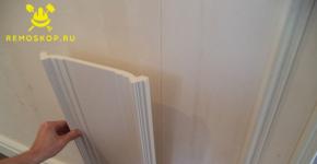
- make a base from the selected material, connecting structural elements with bolts or gluing them;

- drill holes and insert guides into them as in the photo below;

Installing the guides
- assemble a carriage for installing a pen or laser;

Carriage with holes for guides
- assemble the mount;

Mount under the marker

Locking mechanism
- install stepper motors, gears, belts, getting the structure shown below;

Assembled homemade plotter
- connect the electrical circuit;
- install software on a computer;
- put the device into operation after verification.
If use arduino, then the programs discussed above will do. The use of different microcontrollers will require the installation of different software.
When a knife is installed to cut film or paper (cardboard), its penetration depth should be correctly adjusted experimentally.
The above design can be improved by adding automation... Details of the parameters will need to be selected empirically, based on the available ones. Some may need to be purchased.
Both of the considered options for plotters can be done independently, if only there is an old unnecessary technique and desire. Such cheap devices are capable of drawing drawings, cutting out various images and shapes. They are far from industrial analogues, but if it is necessary to create drawings frequently, they will greatly facilitate the work. Moreover, the software is available online for free.
Hello.
Concept
It's hard to imagine, but in some universities you still have to draw graphics by hand (the computer is the work of the devil, of course ...). This annoyed me so much that I decided to put together a graphing machine that I will use. My plotter can print any HPGL drawings.
I also needed a special kind of software. It should not only manage the device, but also be able to develop and save schedules. This is why I decided to write my own application instead of using the existing CNC software.
I used an ATMEG16 microcontroller to control the device. It receives data through a USB-RS232 converter (FT232) connected to the computer's USB port. Data is streamed using my own communication protocol, which will be discussed later. For X and Yoshi, I found two stepper motors from old scanners. They have a built-in mechanism so that the torque is increased without complicating the control. The Z axis is a simple electromagnet (from an old printer, I suppose). All this stuff is powered by a power supply from an HP printer.
Necessary parts and tools.
I spent about $ 25 on the project (I bought everything in Poland, prices may differ in other countries).
Here's a list:

You will also need:
- Soldering iron
- Scissors
- Sandpaper (120-150)
- Glue gun
- Some glue (super glue, wood glue, hot glue)
Step 1: design and preparation
The project was modeled in Blender’e (this is a 3D modeling program).
Green "box" - food. The yellow “box” is the controller. The blue "box" is an LCD display.
The amber parts were made from laminate. The blue details are plexiglass.
Stepper motors, electromagnet - dark gray parts.
Stepper motors, electromagnet and limit switches in dark gray.
In the PDF file you will find drawings of the Plexiglas parts. Cutting is very cheap even in Poland. You need to order 3mm plexiglass parts.

A few words about the X and Yoshi sliders are just furniture rails.
Step 2: soldering
As I said, the device is controlled by an ATmega16. It controls stepper motors and an electromagnet. It also sends data to the LCD.
For communication with the PC, I used the FT232RL chip (USB-UART converter). I used my own communication protocol. These are two TCMT1109 optocouplers that are used to electrically isolate the PC from the controller. The USB-UART converter must be reprogrammed using FTProg (XML file attached below).
There are also 4 switches on the board. One is needed to reset the processor (this was useful during testing), but the rest were installed for future use. Now the middle switch ("OK") is used to receive the start command (I will write about this later).
Today I finally finished the engraver myself and tested it.
Now let's talk about everything in order.
Initially, the idea to assemble a laser engraver was born when I saw a NeJe handicraft on an Ali express - an engraver from DVD drives.
The price is 4-5 thousand rubles, it's expensive. But the toy seems to be interesting.
I sat there, dug the Internet, watched videos on YouTube. It seems that it is not difficult to assemble it yourself.
I had a couple of stepper motors from an Epson inkjet printer (something like 25 steps per revolution), a little aluminum profile from Leroy.


I decided to try from what there is to portray something like. There would only be 2 axes.
I decided to make the drive on belts, it is simpler.
Based on the guides that remained from the printers, I figured out the size and assembled the base. I secured the motor, belt tensioner, guides, installed a movable table and secured the belt.


There are no photos with the belt installed.
Everything would be fine, but the table ran from edge to edge in just 2.5 revolutions of a stepper motor. Such a scheme would not give positioning accuracy.
I disassembled the belt drive, began to think about how to remake the circuit for an M5 lead screw and abandoned it.

Work piled up, there was no time.
At this time, a friend gave me several DVD drives for analysis. Writer DVD RW Sony and a couple of CD-RW DVD-ROM LG.


On trial, I decided to assemble an engraver on pieces of a DVD drive. From what he left, he came to that. In order to understand whether it interests me or not, it is quite enough.
To assemble the engraver on the casing from the CD drive seemed to me not aesthetically pleasing. I decided to assemble a frame for an engraver from a different aluminum profile. I had a square 20x20x1.5, a corner 20x20x1.5, a shank 60x2 and a U-shaped profile 12x15x2. One more task I set myself to get my hands on in working with a profile. Aluminum material is nasty, then the drill will lead away when drilling, then the hand will tremble when cutting, then the canvas will bite. In general, as a training and perfection of skills, it is not superfluous. In the future, I plan to assemble a printer on a profile from Leroy.
The frame was fastened with a rivet. Fast and reliable.
If the goal is to make it cheap and cheerful, you can and should assemble it on the case from the drive.


On the X-axis I used a piece from LG, on the Y-axis I used a piece from Sony. I removed everything I could from the movable carriages of both drives. We don't need this.
For both axes I designed and printed different spacers on the printer. Y-axis threaded.

X-axis short spacers


For Y-axis, designed and printed a table stand. I glued it to the carriage with superglue.


I used a piece of 6mm plexiglass as a table. After assembling the engraver, the plexiglass was glued to the printing table in the same way, with superglue.
Instead of any nuts, washers and spacers, it was convenient for me to print different fasteners on a printer. No glue guns or snot :)
From a square profile 20x20, I cut 4 pieces into the base and posts.
First, I assembled the base of the carriage fastening along the X axis


A piece of a 20x20x1.5 corner was needed to spread the racks, so that a piece with a carriage entered between the racks, a drive along the Y axis.
Assembled the base for the Y-axis. Two pieces of a square profile and an aluminum strip. He fastened it with a rivet.
Steel corners were riveted in place for fastening the portal of the X axis.


I used steel corners from Leroy as the holders of the X-axis posts. Rubles at 14 apiece.
And put it all together.

On the back of the portal X I riveted 2 corners for attaching the electronics.


Almost done mechanically. At the back, I screwed homemade brains through the spacers printed on the printer.


I soldered wires and connectors to the stepper motors


Buying a ready-made laser with a controller on Ali is expensive, in the end I bought only a TTL controller for the laser.
Like this:


For 250 rubles with a penny.
The laser diode was taken from a Sony drive. I took the lens from the LG drive. A laser diode in a square case was inserted into a U-shaped profile, the module with the laser stood up very tightly, and in front of it was placed a lens assembly from LG, with focusing coils and other entrapment. Ideally suited by the way in width and height. In this version, it becomes possible to adjust the focal length from the laser to the lens.
The photo partially shows the design of the laser module itself.

A laser diode with soldered wires and a lens in front of it.

I couldn't think of anything better or easier than to pull the laser module to the X carriage with cable ties. Reliable enough and you can adjust the distance from the laser to the workpiece.
He soldered electronics to the engraver at work. After assembly, he showed his toy to colleagues. And so it began: he would cut the paper, and the black duct tape, and the blue scotch tape, and if he melted a piece of solder black with black? :)
I tell you that the laser leaves a mark on the cardboard, cuts black electrical tape and black polyethylene. The blue tape on the cardboard is cutting.
In general, the toy turned out to be funny.
Already home. Sawed down the length of the laser emitter. I hid the TTL scarf inside the profile.


The program for translating pictures into g-code is called CHPU.
Controls the GRBLController router.
Engraves a picture. The first, so to speak, damn it. Compare with my avatar :)

Naturally, it is necessary to select the engraving mode. And a small fan for blowing would not hurt, blow away the smoke from the cutting. Engraved on a piece of cardboard.
I uploaded the firmware to the board with GRBL 1.1f, it is in the entry about the board.
Regarding the firmware setup:
The stepper motor of a DVD drive usually has 20 steps per revolution.
Screw pitch 3mm.
20/3 = 6.6666666666667 steps per 1mm
Microstep 16 is set on the a4988 drivers.
Respectively 6.6666666666667 * 16 = 106.67
The voltage on the a4988 drivers (for resistances of 100 Ohm in the driver) set 0.24 V
To enable the laser engraver mode in the firmware, you must enter
The laser (via the controller) is connected to the 11th leg of the arduino, with PWM.
Those. the laser power can be adjusted, and the laser can be turned on / off by software.
To turn on the laser, we give the command
The laser will not turn on until the carriage moves.
To turn off the laser, the command
If you forgot to tell about something - ask.
Again, the toy turned out to be interesting, I am satisfied with the toy.
Someday I will reach my hands and finish a large engraver.
PROTECT YOUR EYES! Do not allow direct and reflected laser beam to enter your eyes. Do not look at the working laser without special glasses. Keep pets away from the working engraver!
Like warned.
Pen and pen-and-pencil plotters were once extremely popular. Over time, their production began to decline. But such systems can be used in various fields, including cutting and sewing, engineering, painting, etc. You can find a pen plotter on the market, but it's more interesting to make one yourself, right?
And a user named Miguel Sanchez decided to make a plotter on his own. He chose the Arduino Uno as the control platform. The system also uses NEMA 17 stepper motors and an auxiliary servo to raise and lower the handle.
In addition, metal tubes, belts and several 3D printed parts are used. This whole system is quite simple, and if you have a 3D printer, it's not particularly difficult to make it. Interestingly, initially Miguel decided to use laser cutting to create the necessary parts, but after that he decided to work with a 3D printer.
Sanchez decided to create his own plotter, inspired by the AxiDraw model, which was developed by Evil Mad Scientist.
Here is the first model of a plotter base created from laser cut parts:

After that, the developer decided to modify the system, as well as use a 3D printer to create parts for his plotter.

All models of the details required for printing are laid out by the user in the public domain.
In order to send files to "print", the craftsman used the program