Where to get textolite at home. Textolite - what is it? Properties and characteristics
Homemade textolite
Here I will tell you how to make a textolite with your own hands. The stuff is very helpful. It is durable, does not absorb moisture, durable, easy to process.
In fact, it is plastic, but plastic is reinforced with fibers of the fabric, which gives not only additional strength, but also beauty, so we will try to take care of the beauty of the resulting material.
So what the textolite consists of is glue (epoxy resin) and cotton fabric. It occurred to me to get confused with the manufacture of PCB when I was looking for something to make a handle for a knife, I came across a piece of ordinary factory PCB, I think a good handle will come out, but the color and texture did not suit me at all, so I decided to try to make something prettier
Epoxy resin is easy to buy, the first fabric that came to my mind was old jeans, plus they were also blue on the one side and white on the other, then an interesting pattern similar to a drawing of a tree turned out.
I took the jeans, cut them into pieces of the size I needed, then spread cling film on the table, cut off 2 wooden blocks so that later the future textolite would be clamped between them, wrapped them with cling film, THEN put on disposable medical rubber gloves and began to prepare epoxy glue. I cooked epoxy in a regular tin can. Most people ignore the instructions on the epoxy package. They try to add more hardener, more, so that it hardens faster, no one considers it necessary to heat it at all, however, with an increase in the amount of hardener, although the glue hardens faster, it becomes stone, more fragile, less elastic, which means strength suffers, in addition, the slower hardening will occur, the better the glue will saturate the fabric. Now about heating - the heated glue components are not only easier to remove from the bottles and mix, the heated glue will better saturate the fabric. in general, it is advisable to keep the glue in a LIGHTLY heated state during the gluing process. I will say right away that I underestimated the absorbency of the fabric and I had to mix the glue 2 times, this is theoretically undesirable, because no matter how hard you try to accurately dose the components, the proportions are likely to be slightly different, and as a result, the properties of the final product are slightly different, but in practice I don’t think so. so that it has any noticeable difference, but nevertheless.
Back to our tinned epoxy
I took pieces of jeans one at a time, dipped them into a jar of glue a little "shaking" in the glue, passed them between my fingers to remove excess glue and put them on one of the bars wrapped in cling film. I put the seamy side to the seamy side, the front side to the front side, in my case, this made the future drawing of the detail larger and more distinct .. At the same time, you should try so that there are no air bubbles between the flaps ..
In general, here you can turn on your imagination to the fullest and use various combinations of fabrics, combinations of layers, you can try to soak anything. Imagine one of your household members walking around the house with the words "where are my favorite warm socks" and you shrug your shoulders with a contented look, twirl a knife with a handle made of homemade textolite in your hands and insert it into the sheath, which in a past life were someone's boots :) ) Or, say, you can make a handle for a knife from any of your clothes, which have some symbolic meaning for you, but which you will never wear, leads a knife with a story, something like a talisman;)
Having laid the last flap, I pressed this whole "sandwich" with a second bar wrapped in a film, wrapped it with cling film on top and clamped it in a vice (this will cause excess epoxy to flow out, you need to take care not to get the vice and everything around) squeezed quite hard, after which left alone for 12 hours for compression, you can also use clamps or by drilling holes in the bars, pull them off with bolts, or by making rings of strong rope and putting them on the edges of the bars, tighten them by twisting, using, say, two 150mm nails. In general, who has what opportunities and who is more comfortable.
After complete curing, the textolite is ready for use in any project.
I got this kind of handle
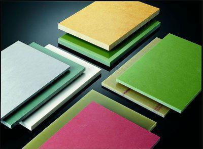
Reinforced with fabrics. Thermosetting synthetic resins act as a binder. And it is not so important which textolite is considered. What it is is quite easy to understand, even from the description.
Some parameters and properties
Depending on the nature of the fibers, PCBs are divided into several groups.
- Basalt textolites based on
- Carbon textolites from carbon.
- Asbestos laminates with asbestos fibers.
- Glass fiber laminates made of glass fibers of various types.
- Organotexoliths made of artificial and
- The textolite itself, the fibers here are cotton
There are other varieties as well. Twill, satin, linen are the types of weaving that differ from the threads themselves. The areal density, thickness, the number of threads per unit length in the direction of the warp and weft of the fabric, the structure and thickness of the thread or tow can be different. There is a special technology, thanks to which textolite is obtained. We have already figured out what it is.

If the interlayer strength is to be particularly high, fabrics of the multilayer type are used. Sometimes there are products where the fibers are made from several types of materials.
What else should you pay attention to?
The manufacturing technology, the amount and properties of the binder, the characteristics of the fabric itself, the nature of the fibers are also important - the parameters that determine what qualities the textolite itself will have. As for the production process itself, it is based on layer-by-layer winding or laying out of fabrics, when a binder is applied to the mandrel in the shape of the product. Foiled textolite is produced in the same way. Next, molding takes place. In addition, textolite plates, plates or sheets must undergo mechanical processing.
Not only fabrics can be varied in the composition, but also binding elements that play the role of impregnation for the filler. Thermosetting most often perform this role, foil textolite is no exception.
On the merits and other parameters
There are a number of qualities inherent in such a material as textolite. What it is is easy to understand from the description of its characteristics.
- The operating temperature range is from -40 to +105 degrees, if the current frequency is about 50 Hz, it remains
- Textolite is a good dielectric, which makes it an irreplaceable assistant in the electrical and energy industries.
- Ease of machining.
- High strength.
- Low density.
- Low coefficient of friction.
Additional Information
Sheet textolite is used in many spheres of life. It can be structural, antifrictional, frictional, electrical insulating, heat insulating and radio engineering material.

In many respects, this is facilitated by the ability to easily transfer mechanical loads, even quite serious ones. So it is especially widely used in the electrical engineering industry. On the basis of PCB, various parts with a structural purpose are made.
Applications and new opportunities
For the production of rings, bushings, ornamental textolite is used. What it is can be understood even without special dictionaries. This material can also be seen in damping panels and gaskets.
In gearboxes, in the distribution mechanisms of various engines, in gearboxes, the presence of bevel and spur gears based on such a material as textolite is often noticeable. The price varies. The elements of centrifugal pumps and turbines are textolite bearings. Textolite can successfully replace getinax as a material for the production of electrical insulating parts. Bases for PCBs made of PCB are made in electronics. In addition, in modern tournaments, it is textolite that becomes the basis for the manufacture of weapons - such its use is quite unexpected.
A little about brands
There is also a kind of textolite, which is called asboplastic and is distinguished separately. It is a fire-resistant and durable material that can withstand heat up to +250 degrees. Differs in chemical resistance, anti-corrosion and electrical insulating properties. The type of binder and filler largely determines what characteristics a particular product will have. For example, anthophyllite asbestos materials give high acid resistance. The manufacturing method and the degree of filling can also influence the existing parameters. In each case, everything is determined individually, this should be followed separately.
Hello dear blog readers. Now the weather outside is wonderful, and I am in a great mood. Today I want to tell you about how you can make high-quality printed circuit boards at home.
] Generally, the method of manufacturing printed circuit boards using laser iron not difficult. Its essence lies in the method of applying a protective pattern to foil textolite.
In our case, we first use a printer to print the protective pattern onto photo paper, its glossy side. Then, as a result of heating with an iron, the softened toner is fried to the surface of the PCB. Read the details of this action ... BUT in the following articles you will find even more useful information from the field of amateur radio technologies, so be sure to subscribe.
So let's get started.
To manufacture a board using the LUT technology, we need:
- foil-clad textolite (one- or two-sided)
- laser printer
- scissors for metal
- glossy photo paper (Lomond)
- solvent (acetone, alcohol, gasoline, etc.)
- sandpaper (with fine abrasive, zero paper is fine)
- drill (usually a motor with a collet chuck)
- a toothbrush (a very useful thing, not only for dental health)
- ferric chloride
- the actual drawing of the board drawn in Sprint-Layout
PCB preparation
We take metal scissors in our hands and cut out a piece of PCB to the size of our future printed circuit board. I used to cut textolite with a hacksaw for metal, but this turned out to be not so convenient compared to scissors, and the textolite dust was very annoying.
The resulting blank of the printed circuit board is thoroughly sanded with sandpaper - zeroing until a uniform mirror shine appears. Then we moisten a piece of cloth with acetone, alcohol or some other solvent, thoroughly wipe and degrease our board.
Our task is to clean our board from oxides and "sweaty hands". Of course, after that we try not to touch our board with our hands.
Preparation of a printed circuit board drawing and transfer to textolite
A pre-drawn drawing of a printed circuit board, we print on photo paper. And in the printer we turn off the toner saving mode, and the drawing is displayed on the glossy side of the photo paper.

Now we take out the iron from under the table and plug it in, let it heat up. We lay the freshly printed sheet of paper on the textolite with the pattern down and begin to iron it with an iron. With photo paper, unlike tracing paper, there is no need to stand on ceremony with self-adhesive backing, "crawl" with an iron until the paper begins to turn yellow.
Here you can not be afraid to overexpose the board, or overdo it with pressure. After we take this sandwich with fried paper and carry it to the bathroom. We begin to roll the paper under a stream of warm water with our fingertips. Next, we take the prepared toothbrush in our hands and thoroughly pass it over the surface of the board. Our task is to peel off the white chalk layer from the surface of the drawing.

We dry the board and check it thoroughly under a bright lamp.
Often the chalk layer is peeled off the first time with a toothbrush, but it happens that this is not enough. In this case, you can use electrical tape. Whitish fibers stick to the tape leaving our scarf clean.
Etching board
To prepare the etching solution, we need ferric chloride FeCL3.

This miracle powder in our radio store costs about 50 rubles. Pour water into a non-metallic vessel and pour ferric chloride there. Usually one part FeCL3 is taken for three parts of water. Next, we immerse our board in a vessel and give it time.
The etching time depends on the thickness of the foil, the temperature of the water, and the freshness of the prepared solution. The hotter the solution, the faster the etching process will take place, but at the same time, in hot water there is a possibility of damaging the protective pattern. Also, the etching process is accelerated by stirring the solution.

Some people adapt a "bulb" from an aquarium for this, or attach a vibration motor from a telephone. We take out the etched board and rinse it under running water. We pour the etching solution into a jar and hide it under the bath, the main thing is that the wife does not see it.
This solution will be useful to us later. We clean the etched scarf from the protective layer of toner. I use acetone for this, but it seems like alcohol or gasoline is not bad either.

Drilling the board
An etched and cleaned PCB needs to be drilled, as it is not always possible to use surface mounting. I have a small drill bit in store for drilling the board. It is a DPM type motor with a collet chuck mounted on the shaft. I took it in a radio store for 500r. But I think you can use any other motor for this, for example, from a tape recorder.

We drill the board with a sharp drill, trying to maintain perpendicularity. Perpendicularity is especially important when making double-sided boards. We do not need punching holes for drilling, since the holes in the foil were formed automatically during etching.
We go over the board with a zero sandpaper, removing burrs after drilling, and get ready for tinning our board.
Tinning the board
I try to solicit my boards, and I do it for several reasons:
- The tinned board is more resistant to corrosion, and after a year you will not see any traces of rust on your device.
- A layer of solder in the printed pattern increases the thickness of the conductive layer, thus reducing the resistance of the conductor.
- It is easier to solder radio components on a pre-tinned board, prepared surfaces contribute to high-quality soldering.
Degrease the board and clean it from oxide. We will use acetone, and then literally dip it in a solution of ferric chloride for a second. We paint the turned pink board with flux. Next, we take out a more powerful soldering iron and, having typed a small amount of solder on the tip, with quick movements we go along the paths of our printed pattern. It remains only to walk a little with sandpaper over the drawing, and as a result we get a beautiful, shiny scarf.

Where can you buy
Where can you buy foil textolite? Yes, however, not only textolite but also other tools for radio amateur creativity.
Currently, I do not have any problems with this, since there are several points of decent radio stores in my city. There I buy textolite and everything that is required.
At one time, when there was no normal radio store in my city, I ordered all the materials, tools and radio parts from the online store. One of these online stores where you can find textolite and not only is Dessie's store, by the way I even talk about him.
Custom PCBs
There are situations when there is a drawing of a printed circuit board, but you absolutely do not want to face technological problems, and the printed circuit board is oh so needed. Or it happens that you don't mind trying, comprehending all the mysteries of this process, but there is no time for evil and it is not known what it will lead to (the first result is not always close to the ideal) In this case, you can do it easier, you can get a high-quality result.
So ATTENTION !!! If you are interested in custom-made PCBs then be sure to read!
Well, so we got acquainted with the method of making printed circuit boards with our own hands at home. Necessarily subscribe to new articles , because there will be a lot of interesting and useful things in the future.
In addition, relatively recently, another progressive method of subscribing through the form of the Email mailing service has appeared, this method is notable for the fact that everyone who subscribes receives a GIFT !!!, and this gift will undoubtedly be appreciated by any radio amateur. So people subscribe and get nice bonuses, so welcome.
So build your devices, do printed circuit boards, a LUT technology will help you.
Best regards, Vladimir Vasiliev.
I propose to watch a good selection of videos on each stage of LUT - technology.
Printed circuit board Is a dielectric base, on the surface and in the volume of which conductive paths are applied in accordance with the electrical circuit. The printed circuit board is designed for mechanical fastening and electrical connection between each other by soldering the leads installed on it, electronic and electrical products.
Operations for cutting a workpiece from fiberglass, drilling holes and etching a printed circuit board to obtain current-carrying tracks, regardless of the method of drawing a pattern on a printed circuit board, are performed using the same technology.
Manual application technology
PCB tracks
Preparing the template
The paper on which the PCB layout is drawn is usually thin and for more accurate drilling of holes, especially in the case of using a hand-made homemade drill, so that the drill does not lead to the side, you need to make it more dense. To do this, you need to glue the printed circuit board pattern onto thicker paper or thin thick cardboard using any glue, such as PVA or Moment.

Cutting the workpiece
A preform of foil-clad fiberglass of a suitable size is selected, a printed circuit board template is applied to the workpiece and outlined around the perimeter with a marker, a soft simple pencil or by drawing a line with a sharp object.

Next, fiberglass is cut along the lines drawn using metal scissors or cut out with a hacksaw for metal. Cut off faster with scissors and there is no dust. But it must be borne in mind that when cutting with scissors, glass fiber laminate bends strongly, which somewhat worsens the strength of the copper foil gluing and if the elements need to be soldered, the tracks may peel off. Therefore, if the board is large and with very thin tracks, then it is better to cut it off with a hacksaw for metal.

The template of the printed circuit board pattern is glued onto the cut out workpiece with the help of glue. Moment, four drops of which are applied at the corners of the workpiece.

Since the glue sets in just a few minutes, you can immediately start drilling holes for radio components.
Drilling holes
It is best to drill holes using a special mini drilling machine with a carbide drill with a diameter of 0.7-0.8 mm. If a mini drilling machine is not available, then you can drill holes with a low-power drill with a simple drill. But when working with a universal hand drill, the number of broken drills will depend on the firmness of your hand. One drill is definitely not enough.

If the drill cannot be clamped, then you can wrap its shank with several layers of paper or one layer of emery cloth. It is possible to wind tightly a turn on the shank to a turn of a thin metal wire.

After finishing drilling, it is checked whether all holes have been drilled. This is clearly visible if you look at the printed circuit board in the light. As you can see, there are no missed holes.
Topographic drawing
In order to protect the places of the foil on the fiberglass, which will be conductive paths, from destruction during etching, they must be covered with a mask that is resistant to dissolution in an aqueous solution. For the convenience of drawing tracks, it is better to pre-outline them using a soft, simple pencil or marker.
Before applying the markings, it is imperative to remove the traces of glue. The moment with which the PCB template was glued. Since the glue is not very hard, it can be easily removed by rolling it with your finger. The surface of the foil must also be degreased with a rag with any means, such as acetone or white alcohol (this is the name of refined gasoline), you can also use any detergent for washing dishes, such as Ferry.

After marking the tracks of the printed circuit board, you can start drawing their pattern. Any waterproof enamel is well suited for drawing tracks, for example, alkyd enamel of the PF series, diluted to a suitable consistency with a solvent of white alcohol. You can draw tracks using different tools - a glass or metal drawing pen, a medical needle and even a toothpick. In this article, I will show you how to draw PCB tracks using a drawing plane and a ballerina, which are designed for drawing on paper with ink.

Previously, there were no computers, and all drawings were drawn with simple pencils on a Whatman paper and then translated in ink onto tracing paper, from which copies were made using copiers.
The drawing begins with the contact pads, which are drawn by the ballerina. To do this, you need to adjust the gap of the sliding jaws of the ballerina's drawing pen to the required line width and to set the circle diameter, adjust the second screw by moving the drawing pen away from the axis of rotation.
Next, the ballerina's drawing pen is filled with paint to a length of 5-10 mm with a brush. To apply a protective layer to a printed circuit board, PF or GF paint is best suited, since it dries slowly and allows you to work calmly. NC brand paint can also be used, but it is difficult to work with it, as it dries quickly. The paint should fit well and not spread. Before drawing, the paint must be diluted to a liquid consistency, adding a suitable solvent to it little by little with vigorous stirring and trying to paint on scraps of fiberglass. To work with paint, it is most convenient to pour it into a bottle of manicure varnish, in the twist of which there is a brush resistant to solvents.
After adjusting the ballerina's flight controller and obtaining the required line parameters, you can start applying the contact pads. To do this, the sharp part of the axis is inserted into the hole and the base of the ballerina is rotated in a circle.

With the correct adjustment of the planer and the desired consistency of paint, circles of a perfectly round shape are obtained around the holes on the printed circuit board. When the ballerina begins to draw poorly, the dry paint residues are removed from the drawing pen gap with a cloth and the drawing pen is filled fresh. to outline all the holes on this printed circuit board in circles, it took only two refills of the flight feeder and no more than two minutes of time.
When the circular pads on the board are drawn, you can start drawing the conductive tracks using a hand-drawn planer. Preparing and adjusting a manual refeeding device is no different from preparing a ballerina.
The only thing that is additionally needed is a flat ruler, with pieces of rubber glued on one of its sides along the edges, 2.5-3 mm thick, so that the ruler does not slip during operation and the fiberglass, without touching the ruler, can freely pass under it. A wooden triangle is best suited as a ruler, it is stable and at the same time can serve as a hand support when drawing a printed circuit board.

So that the printed circuit board does not slip when drawing tracks, it is advisable to place it on a sheet of sandpaper, which is two sandpaper sheets riveted together by paper sides.

If, when drawing paths and circles, they touch, then you should not take any action. It is necessary to allow the paint on the printed circuit board to dry to a state where it will not stain when touched and remove the excess part of the pattern with the help of the knife's edge. In order for the paint to dry faster, the board must be placed in a warm place, for example, on a heating battery in winter. In the summer - under the rays of the sun.

When the pattern on the printed circuit board is completely applied and all defects are corrected, you can proceed to etching it.
Printed circuit board drawing technology
using a laser printer
When printing on a laser printer, the image formed by the toner from the photo drum, on which the laser beam painted the image, is electrostatically transferred onto a paper carrier. The toner is held onto the paper, preserving the image, only by electrostatics. To fix the toner, paper is rolled between rollers, one of which is a thermal oven heated to a temperature of 180-220 ° C. The toner melts and permeates the texture of the paper. After cooling, the toner hardens and adheres firmly to the paper. If the paper is heated again to 180-220 ° C, the toner will become liquid again. It is this property of the toner that is used to transfer the image of conductive tracks to a printed circuit board at home.
After the file with the printed circuit board is ready, you need to print it using a laser printer to paper. Please note that the image of the printed circuit board for this technology must look from the side of the installation of the parts! An inkjet printer is not suitable for these purposes, since it works on a different principle.
Preparing a paper template for transferring a design to a PCB
If you print a drawing of a printed circuit board on ordinary paper for office equipment, then due to its porous structure, the toner will penetrate deeply into the body of the paper and when the toner is transferred to the printed circuit board, most of it will remain in the paper. In addition, it will be difficult to remove the paper from the circuit board. You will have to soak it in water for a long time. Therefore, to prepare a photomask, you need paper that does not have a porous structure, for example, photographic paper, a backing from self-adhesive films and labels, tracing paper, pages from glossy magazines.
I use tracing paper from old stocks as paper for printing the PCB design. The tracing paper is very thin and it is impossible to print the template directly on it, it gets jammed in the printer. To solve this problem, before printing on a piece of tracing paper of the required size, apply a drop of any glue in the corners and glue it onto a sheet of A4 office paper.

This technique allows you to print a printed circuit board design even on the thinnest paper or film. In order for the toner thickness of the image to be maximum, before printing, you need to configure the "Printer Properties" by turning off the economical printing mode, and if this function is not available, then select the coarsest type of paper, such as cardboard or something similar. It is quite possible that the first time you will not get a good print, and you will have to experiment a little, choosing the best printing mode for a laser printer. In the resulting print of the drawing, the tracks and contact pads of the printed circuit board should be dense without gaps and smearing, since retouching at this technological stage is useless.

It remains to cut the tracing paper along the contour and the template for manufacturing the printed circuit board will be ready and you can proceed to the next step, transferring the image to fiberglass.
Transferring a drawing from paper to fiberglass
Transferring the PCB design is the most critical step. The essence of the technology is simple, the paper, with the side of the printed pattern of the printed circuit board tracks, is applied to the copper foil of the fiberglass and is pressed with great effort. Next, this sandwich is heated to a temperature of 180-220 ° C and then cooled to room temperature. The paper peels off and the design remains on the PCB.
Some craftsmen suggest transferring a drawing from paper to a printed circuit board using an electric iron. I tried this method, but the result was unstable. It is difficult to simultaneously heat the toner to the correct temperature and evenly press the paper over the entire surface of the circuit board as the toner hardens. As a result, the pattern is not completely transferred and there are gaps in the pattern of the printed circuit board tracks. The iron may not have been hot enough even though the regulator was set to the maximum iron heat. I didn't want to open the iron and readjust the thermostat. Therefore, I used a different technology, less laborious and providing one hundred percent results.
I glued tracing paper with a pattern printed on it to the cut-out to the size of the printed circuit board and degreased with acetone. On top of the tracing paper I put, for a more even pressure, heels of office paper sheets. The resulting package was put on a sheet of plywood and covered with a sheet of the same size on top. This whole sandwich was clamped with maximum force in the clamps.

It remains to heat the made sandwich to a temperature of 200 ° C and cool. An electric oven with a temperature controller is ideal for heating. It is enough to place the created structure in a cabinet, wait for the set temperature to reach and after half an hour remove the board for cooling.

If an electric oven is not available, you can also use a gas oven by adjusting the temperature with the gas supply knob using the built-in thermometer. If there is no thermometer or it is faulty, then women can help, the position of the regulator knob is suitable, at which the pies are baked.

Since the ends of the plywood were warped, just in case, he clamped them with additional clamps. to avoid such a phenomenon, it is better to clamp the printed circuit board between metal sheets 5-6 mm thick. You can drill holes in their corners and clamp the printed circuit boards, tighten the plates with screws and nuts. An M10 will suffice.
After half an hour, the structure has cooled down enough for the toner to harden, the board can be removed. At the first glance at the removed printed circuit board, it becomes clear that the toner has passed from the tracing paper to the board perfectly. The tracing paper fit snugly and evenly along the lines of the printed tracks, pad rings and marking letters.

The tracing paper came off easily from almost all the traces of the printed circuit board, the tracing paper was removed with a damp cloth. But all the same it was not without gaps in several places on the printed tracks. This can happen as a result of uneven printing of the printer or remaining dirt or corrosion on the fiberglass foil. Gaps can be painted over with any waterproof paint, nail polish or retouched with a marker.

To check the suitability of the marker for retouching the printed circuit board, you need to draw lines with it on paper and moisten the paper with water. If the lines are not blurry, then the marker is suitable for retouching.

It is best to etch a PCB at home in a solution of ferric chloride or hydrogen peroxide with citric acid. After etching, the toner can be easily removed from the printed tracks with a swab dipped in acetone.
Then holes are drilled, conductive tracks and contact pads are tinned, radioelements are sealed.

A printed circuit board with radio components installed on it took this form. The result is a power supply and switching unit for the electronic system, complementing an ordinary toilet with a bidet function.
PCB Etching
To remove copper foil from unprotected areas of foil-clad fiberglass in the manufacture of printed circuit boards at home, radio amateurs usually use a chemical method. The printed circuit board is placed in an etching solution and, due to a chemical reaction, the copper, which is not protected by the mask, dissolves.
Pickling solution recipes
Depending on the availability of components, radio amateurs use one of the solutions listed in the table below. Pickling solutions are ranked in order of popularity for their use by radio amateurs at home.
| Solution name | Composition | Quantity | Cooking technology | Dignity | disadvantages |
|---|---|---|---|---|---|
| Hydrogen peroxide plus citric acid | Hydrogen peroxide (H 2 O 2) | 100 ml | Dissolve citric acid and table salt in 3% hydrogen peroxide solution | Component availability, high etching rate, safety | Not stored |
| Citric acid (C 6 H 8 O 7) | 30 g | ||||
| Table salt (NaCl) | 5 g | ||||
| Ferric chloride aqueous solution | Water (H 2 O) | 300 ml | Dissolve ferric chloride in warm water | Sufficient etching rate, reusable | Low availability of ferric chloride |
| Ferric chloride (FeCl 3) | 100 g | Hydrogen peroxide plus hydrochloric acid | Hydrogen peroxide (H 2 O 2) | 200 ml | Pour 10% hydrochloric acid into a 3% hydrogen peroxide solution | High etching rate, reusable | High accuracy required |
| Hydrochloric acid (HCl) | 200 ml | ||||
| Aqueous solution of copper sulfate | Water (H 2 O) | 500 ml | Dissolve table salt in hot water (50-80 ° C), and then copper sulfate | Component availability | Toxicity of copper sulfate and slow etching, up to 4 hours |
| Copper sulfate (CuSO 4) | 50 g | ||||
| Table salt (NaCl) | 100 g | ||||
Etching PCBs in metal dishes are not allowed... To do this, you need to use a container made of glass, ceramic or plastic. It is allowed to dispose of the spent pickling solution down the drain.
Etching solution of hydrogen peroxide and citric acid
A solution based on hydrogen peroxide with citric acid dissolved in it is the safest, most affordable and fast working solution. Of all the solutions listed, this is the best by all criteria.

Hydrogen peroxide can be purchased at any drug store. It is sold in the form of a liquid 3% solution or tablets called hydroperite. To obtain a liquid 3% solution of hydrogen peroxide from hydroperite, you need to dissolve 6 tablets weighing 1.5 grams in 100 ml of water.
Crystals of citric acid are available at any grocery store in 30 or 50 gram sachets. Table salt can be found in any home. 100 ml of etching solution is enough to remove 35 µm copper foil from a 100 cm 2 PCB. The spent solution is not stored and cannot be reused. By the way, citric acid can be replaced with acetic acid, but because of its pungent smell, the printed circuit board will have to be etched in the open air.
Ferric chloride pickling solution
The second most popular pickling solution is an aqueous solution of ferric chloride. Previously, it was the most popular, since ferric chloride was easy to get at any industrial enterprise.

The pickling solution is not picky about the temperature, it picks out quickly enough, but the pickling rate decreases as the ferric chloride in the solution is consumed.

Ferric chloride is very hygroscopic and therefore quickly absorbs water from the air. As a result, a yellow liquid appears at the bottom of the can. This does not affect the quality of the component and such ferric chloride is suitable for preparing the pickling solution.
If the used ferric chloride solution is stored in an airtight container, then it can be reused. To be regenerated, it is enough to pour iron nails into the solution (they will immediately be covered with a loose layer of copper). Leaves hard-to-remove yellow spots on contact with any surface. Currently, ferric chloride solution for the manufacture of printed circuit boards is used less often due to its high cost.
Etching solution based on hydrogen peroxide and hydrochloric acid
Excellent pickling solution, provides high pickling rate. Hydrochloric acid with vigorous stirring is poured into a 3% aqueous solution of hydrogen peroxide in a thin stream. It is unacceptable to pour hydrogen peroxide into acid! But due to the presence of hydrochloric acid in the etching solution, great care must be taken when etching the board, since the solution corrodes the skin of the hands and spoils everything it gets on. For this reason, it is not recommended to use a pickling solution with hydrochloric acid at home.
Etching solution based on copper sulfate
The method of manufacturing printed circuit boards with the use of copper sulfate is usually used when it is impossible to manufacture an etching solution based on other components due to their inaccessibility. Copper sulfate is a toxic chemical and is widely used for pest control in agriculture. In addition, the etching time of the printed circuit board is up to 4 hours, while it is necessary to maintain the temperature of the solution at 50-80 ° C and to ensure a constant change of the solution at the etched surface.
Etching technology of printed circuit boards
For etching the board in any of the above etching solutions, glass, ceramic or plastic dishes, for example, from dairy products, are suitable. If you don't have a suitable size of container at hand, then you can take any box of thick paper or cardboard of a suitable size and line its inside with plastic wrap. An etching solution is poured into the container and a printed circuit board is placed on its surface with a pattern down. Due to the forces of the surface tension of the liquid and the low weight, the board will float.

For convenience, you can glue the cork from a plastic bottle to the center of the board with glue. The plug will simultaneously serve as a handle and a float. But there is a danger that air bubbles form on the board and copper will not be corroded in these places.

To ensure even copper etching, you can place the PCB on the bottom of the container with the pattern upside down and occasionally wiggle the bowl by hand. After a while, depending on the etching solution, copper-free areas will begin to appear, and then the copper will dissolve completely over the entire surface of the PCB.

After the final dissolution of copper in the etching solution, the printed circuit board is removed from the bath and thoroughly rinsed under running water. The toner is removed from the tracks with a rag soaked in acetone, and the paint is well removed with a rag soaked in a solvent that was added to the paint to obtain the desired consistency.
Preparing the printed circuit board for the installation of radio components
The next step is to prepare the printed circuit board for the installation of radioelements. After removing the paint from the board, the paths need to be processed in a circular motion with fine sandpaper. You do not need to get carried away, because the copper paths are thin and you can easily grind them off. Just a few passes with a low pressure abrasive are enough.

Further, the current-carrying tracks and contact pads of the printed circuit board are coated with an alcohol-rosin flux and soft-soldered with an electric soldering iron. so that the holes on the PCB are not tightened with solder, you need to take a little on the tip of the soldering iron.

After completing the manufacture of the printed circuit board, it remains only to insert the radio components into the intended positions and solder their leads to the sites. Before soldering, the legs of the parts must be moistened with alcohol-rosin flux. If the legs of the radio components are long, then they must be cut with side cutters before soldering to a protrusion length of 1-1.5 mm above the surface of the printed circuit board. After completing the installation of parts, you need to remove the remnants of rosin using any solvent - alcohol, white alcohol or acetone. They all successfully dissolve rosin.

It took no more than five hours to implement this simple capacitive relay circuit from tracing the circuit board to creating a working prototype, much less than the layout of this page.