Connect Ds18b20 to Arduino. DS18B20. Russian description
DS18B20 digital temperature sensor that works using the 1-Wire protocol. Used when developing a home weather station on the Arduino.
DS18B20 Sensor Description
DS18B20 is a digital thermometer with a programmable resolution of 9 to 12 bits, which can be stored in the device's EEPROM. DS18B20 communicates over the 1-Wire bus and can be both the only device on the line and work in a group. All processes on the bus are controlled by a central microprocessor.
The sensor's measuring range is from –55 to +125 ° C and an accuracy of 0.5 ° C in the range from –10 to +85 ° C. In addition, the DS18B20 can be powered by a data line voltage in the absence of an external voltage source.
Each DS18B20 sensor has a unique 64-bit serial code that allows you to communicate with multiple DS18B20 sensors installed on the same bus. The first 8 bits are the serial code (for DS18B20 - 28h), then 48 bits of the unique number, and at the end 8 bits of the CRC code. This principle allows the use of a single microprocessor to monitor a variety of DS18B20 sensors distributed over a large area.
DS18S20 sensor features:
- 1-Wire interface;
- measured temperature from –55 to +125 ° C;
- accuracy of 0.5 ° C in the range from –10 to +85 ° C;
- temperature reads 9 data bits;
- time for temperature conversion - 750 ms (maximum).
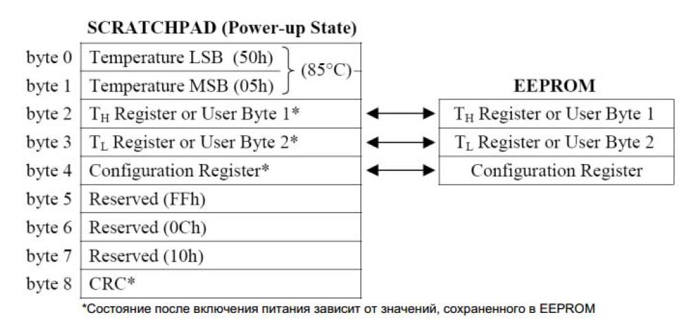
The temperature data is stored in the RAM of the sensor. The memory consists of an operative ROM and a non-volatile EEPROM:
The first two bytes - contain data on the measured temperature;
The third and fourth bytes store the upper (TH) and lower (TL) temperature limits;
The fifth and sixth are not used;
Seventh and eighth - bytes counters. They can be used to more accurately measure temperature;
The ninth byte stores the CRC code of the previous eight.
 |
In addition to general commands for all types of 1-Wire devices presented in the table, the sensor can execute the following commands:
Alarm Search - the operation of this command is identical to the operation of address search, except that in this case only those sensors will respond that had the temperature exceeded the set limits during the last measurement (above TH or below TL);
Convert t - convert temperature. The sensor will measure and record current temperature data. If the master device sends read time slots for this command, while the conversion is not completed, the DS18S20 will issue a “0” to the line, and after the conversion is completed, “1”.
Write Scratchpad - write to memory. This command allows you to write 3 bytes in the sensor memory. The first byte is written to TH, the second to TL, and the third byte is written to the fifth byte of memory — this is the configuration byte;
Read Scratchpad - reading memory. The command allows us to read the sensor memory. In response to this command, the sensor will return 9 bytes of its memory, starting with the 0th byte of TEMPERATURE LSB and ending with the eighth - CRC;
Copy scratchpad - copy memory. The sensor will copy the contents of the RAM - TH and TL into the EEPROM.
The sequence of commands to obtain data from the sensor about the temperature:
Perform RESET and search for devices on the 1-Wire line.
Issue command 0x44 to start temperature conversion by the sensor.
Wait at least 750 ms.
You can use the OneWire library to work with sensors with the 1-Wire interface.
The sample for receiving data from the DS18B20 temperature sensor and data output to the serial port using the OneWire library is presented in the example
Sketch code
#include
OneWire ds (10); // 1-Wire line will be on pin 10
void setup (void)
Serial.begin (9600);
byte present \u003d 0; byte data; byte addr;
if (! ds.search (addr)) (Serial.print ("No more addresses. \\ n"); ds.reset_search ();
if (OneWire :: crc8 (addr, 7)! \u003d addr) (Serial.print ("CRC is not valid! \\ n"); return;
if (addr! \u003d 0x28) (
Serial.print ("Device is not a DS18B20 family device. \\ N"); return;
ds.reset (); ds.select (addr);
ds.write (0x44,1); // start the conversion delay (750); // waiting for 750ms
present \u003d ds.reset (); ds.select (addr);
ds.write (0xBE); // read sensor RAM
for (i \u003d 0; i< 9; i++) { // обрабатываем 9 байт data[i] = ds.read();
Serial.print (data [i], HEX); Serial.print ("");
// calculate the temperature :)
int HighByte, LowByte, TReading, Tc_100; LowByte \u003d data;
Serial.print ("LB \u003d"); Serial.print (LowByte, HEX); HighByte \u003d data;
Serial.print ("HB \u003d"); Serial.print (HighByte, HEX); TReading \u003d (HighByte<< 8) + LowByte;
Tc_100 \u003d TReading / 2;
Serial.print ("T \u003d"); Serial.print (Tc_100); Serial.println ();
The DS18B20 is a digital temperature sensor. The sensor is very easy to use. First, it is digital, and secondly - it has only one contact, from which we receive a useful signal. That is, you can connect to a single Arduino at the same time a huge number of these sensors. Pins will be more than enough. Moreover, you can even connect several sensors to one pin on the Arduino! But first things first.
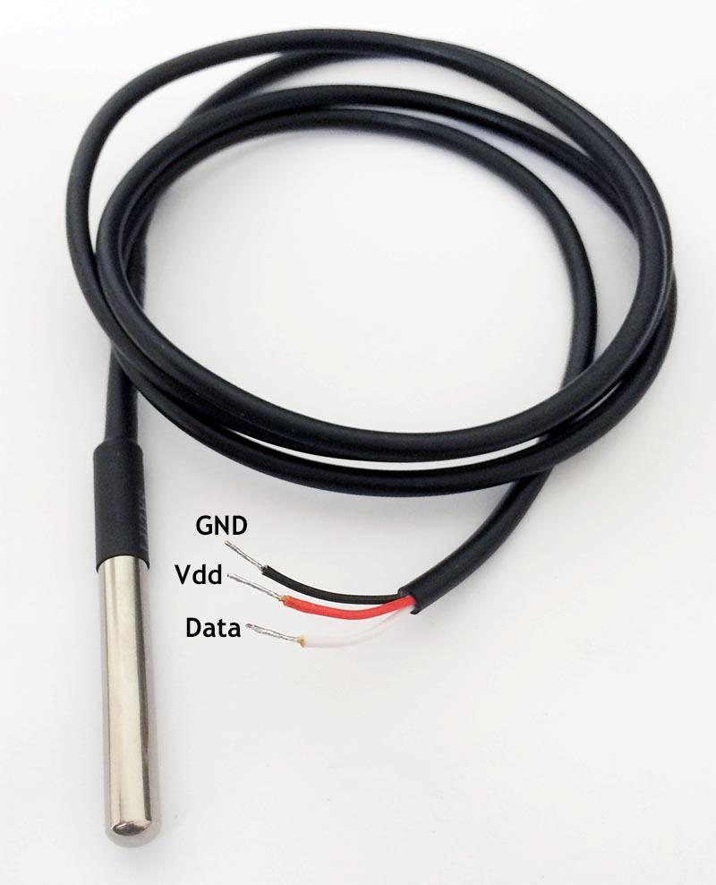
DS18B20 has various form factors. So the choice of which one to use is yours. Three options are available: 8-Pin SO (150 mils), 8-Pin µSOP, and 3-Pin TO-92. Surfing on eBay or Aliexpress shows that the Chinese are offering a TO-92 version in a waterproof case. That is, you can safely dip such a miracle in the water, use it in the rain, etc. etc. These sensors are manufactured with three output contacts (black - GND, red - Vdd and white - Data).
The various form factors of the DS18B20 sensors are shown in the figure below.
Model DS18B20 in a waterproof case:
DS18B20 is easy to use. You can power it through the contact data (in this case, you use only two of the three contacts to connect!). The sensor operates in a voltage range from 3.0 V to 5.5 V and measures temperature in the range from -55 ° C to + 125 ° C (from -67 ° F to + 257 ° F) with an accuracy of ± 0.5 ° C (from -10 ° C up to + 85 ° C).
Another cool feature: you can connect up to 127 sensors in parallel! and read the temperature readings from each separately. It is not entirely clear in which project such a thing may be needed, but you can connect two sensors and control the temperature in the refrigerator and freezer. In this case, you leave free a bunch of pins on the Arduino ... In general, the feature is nice.
What you need to control the temperature with the Arduino and DS18B20
Software
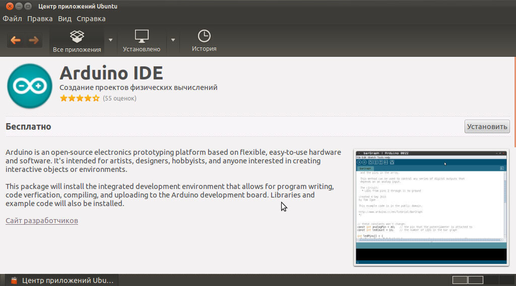
- Naturally, you need an Arduino IDE;
- Library OneWire library, which greatly facilitates the work with the Arduino and sensor DS18B20;
- Sketch...
We load the sketch on Arduino
The sketch below is in the OneWire library, in the examples category. Go to “File” - “Examples” - “OneWire” and select example “DS18x20_Temperature”. The program code is presented below.
This example uses the OneWire Library to collect data from all connected DS28B20 temperature sensors (how to connect several sensors described at the end of the article) and display them in the Arduino IDE serial monitor window.
In the serial monitor window, you will see something like the following:
ROM \u003d 28 88 84 82 5 0 0 6A
No more addresses.
ROM \u003d 28 88 84 82 5 0 0 6A
Data \u003d 1 56 1 4B 46 7F FF A 10 D1 CRC \u003d D1
Temperature \u003d 21.37 Celsius, 70.47 Fahrenheit
No more addresses.
ROM \u003d 28 88 84 82 5 0 0 6A
Data \u003d 1 56 1 4B 46 7F FF A 10 D1 CRC \u003d D1
Temperature \u003d 21.37 Celsius, 70.47 Fahrenheit
Make sure you specify the correct pins!
In line 10, where “OneWire ds (2);” is indicated, a pin is set to which the data contact from the sensor is connected.
In this example, pin 2 is used, but the default pin values \u200b\u200bin the OneWire example are 10. It can also be used.
#include & ltOneWire.h & gt
// example of using the library OneWire DS18S20, DS18B20, DS1822
OneWire ds (2); // on pin 10 (4.7 kΩ resistor needed)
void setup (void) (
Serial.begin (9600);
void loop (void) (
byte present \u003d 0;
float celsius, fahrenheit;
if (! ds.search (addr)) (
Serial.println ("No more addresses.");
Serial.println ();
ds.reset_search ();
Serial.print ("ROM \u003d");
Serial.write ("");
Serial.print (addr [i], HEX);
if (OneWire :: crc8 (addr, 7)! \u003d addr) (
Serial.println ("CRC is not valid!");
Serial.println ();
// first byte identifies the chip
Serial.println ("Chip \u003d DS18S20"); // or older DS1820
Serial.println ("Chip \u003d DS18B20");
Serial.println ("Chip \u003d DS1822");
Serial.println ("Device is not a DS18x20 family device.");
ds.select (addr);
delay (1000); // 750 may be enough, but maybe not enough
// we could use ds.depower () here, but the reset will take care of it
present \u003d ds.reset ();
ds.select (addr);
Serial.print ("Data \u003d");
Serial.print (present, HEX);
Serial.print ("");
data [i] \u003d ds.read ();
Serial.print (data [i], HEX);
Serial.print ("");
Serial.print ("CRC \u003d");
Serial.print (OneWire :: crc8 (data, 8), HEX);
Serial.println ();
// convert this to actual temperature
// since the result is a 16 bit integer, it must be stored in
// variable with the data type "int16_t", which is always 16 bits,
// even if we are compiling on a 32-bit processor
int16_t raw \u003d (data
if (data \u003d\u003d 0x10) (
raw \u003d (raw & 0xFFF0) + 12 - data;
byte cfg \u003d (data & 0x60);
// for small values, small bits are not defined, let's reset them
if (cfg \u003d\u003d 0x00) raw \u003d raw & ~ 7; // resolution of 9 bits, 93.75 ms
else if (cfg \u003d\u003d 0x20) raw \u003d raw & ~ 3; // resolution of 10 bits, 187.5 ms
else if (cfg \u003d\u003d 0x40) raw \u003d raw & ~ 1; // resolution of 11 bits, 375 ms
//// default resolution is 12 bits, the conversion time is 750 ms
celsius \u003d (float) raw / 16.0;
fahrenheit \u003d celsius * 1.8 + 32.0;
Serial.print ("Temperature \u003d");
Serial.print (celsius);
Serial.print ("Celsius,");
Serial.print (fahrenheit);
Serial.println ("Fahrenheit");
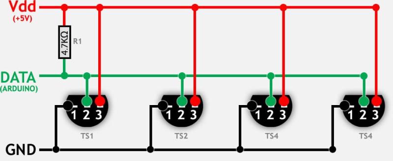
How to connect multiple DS18B20 sensors to Arduino?
You can connect multiple DS18B20 digital temperature sensors in parallel. In this case, the OneWire library will allow you to read data from all sensors simultaneously.
The following are two methods for connecting sensors.
For a large number of sensors (more than 10), it is necessary to use resistors with less resistance (for example, 1.6 KΩ or even less).
In addition, if you connect in parallel more than 10 sensors, problems may arise (errors in taking readings). Therefore, it is recommended to install an additional resistor of 100 ... 120 Ohms between the data contact on the Arduino and the data on each sensor!
The result of the previous sketch with two connected sensors can look like this:
ROM \u003d 28 88 84 82 5 0 0 6A
Data \u003d 1 51 1 4B 46 7F FF F 10 FE CRC \u003d FE
Temperature \u003d 21.06 Celsius, 69.91 Fahrenheit
ROM \u003d 28 DA CA 27 5 0 0 49
Data \u003d 1 4E 1 4B 46 7F FF 2 10 D9 CRC \u003d D9
Temperature \u003d 20.87 Celsius, 69.57 Fahrenheit
No more addresses.
Choosing the right sensor
It would be nice to know from which sensor you get the data when you use several sensors in parallel. How to do it?
Serial number
Since the sensors are digital, each of them has an individual serial number, which can be used to identify one or another sensor. It seems to be all simple. But ... we need to pre-determine these serial numbers before using them to identify the sensor, right?
You could draw on the examples above that the sketch gives us the data in the form of a 64-bit serial number - the value “ROM”. For example:
28 88 84 82 5 0 0 6A or 28 DA CA 27 5 0 0 49 in the example above.
Do not forget, if you use a large number of sensors at the same time (10 or more), you need to add 100 ... 120 Ohm resistors between the data contacts from the DS18B20 sensor and the data pin to the Arduino (for each sensor!).
Below is a diagram of parallel connection of several sensors using three contacts.
Leave your comments, questions and share your personal experience below. In the discussion often new ideas and projects are born!
The DS18B20 is a standard temperature sensor designed and manufactured on a digital basis. It is very easy to operate due to the simplicity of the design, as well as its adaptive capabilities to work with the Arduino Processing LCD.
Its main advantages are:
- Having only one contact for a useful signal. This makes it possible to connect a huge number of identical DS18B20 sensors to a single Arduino Processing LCD.
- Digital functioning system.
- Ability to connect a huge number of identical sensors to a single pin Arduino Processing LCD.
 Connect DS18B20 sensor to Arduino
 All DS18B20 sensors have several form factors that can significantly facilitate the work with them. The right to choose the form factor itself always, of course, remains with the client. Today, the market is dominated by 3 variants of this product, namely: 8Pin SO (150 mils), 8Pin µSOP and 3Pin TO92. The information that we have gathered indicates that Chinese manufacturers also offer to purchase a 3Pin TO92 sensor, equipped with a special moisture barrier. This will give you the opportunity to immerse the device in liquid, to use during bad weather and in other cases. All sensors always have 3 output contacts: black, red and white. They correspond to the values \u200b\u200bof GND, Vdd and Data, respectively.
Additional convenience of operation of DS18B20 for Arduino Processing LCD is provided that it can be connected to the power supply network through white contact. In this case, you will use only a couple of contacts instead of the three that are required for a normal connection. The sensor is able to function at a voltage in the network from 3 to 5.5 Volts, as well as to record temperature changes, if it is in the range from -55 to plus 125 Celsius. The error that the thermostat can give out when measuring the temperature is 0.5 degrees Celsius.
A very pleasant circumstance when using the DS18B20 sensor for the Arduino Processing LCD is that you can connect up to 127 DS18B20 sensors in parallel to one device at a time.
It is difficult to imagine a situation in which this may be required. But if you install, for example, one sensor in the refrigerator and the other in the freezer, it will be very useful. Again, in this case, you just have a huge amount of free pins for the Arduino.
What you need to configure the operation of the sensor DS18B20 for Arduino Processing LCD
From the software you will need:
- The OneWire library database is notable for the fact that it greatly simplifies the work with both the Arduino itself and all sensors, including the DS18B20.
- Sketch.
The program "Arduino" can be downloaded from its official website - there is its latest version in the public domain.
The OneWire Library database can be downloaded on OneWireProjectPage. It is advisable to download the latest version of it to your computer.
Of the equipment you will need:
- Nano-sensor for measuring temperature indicators DS 18B20 in the amount of at least one copy.
- Controller "Arduino".
- Thermostat.
- Connectors in the amount of 3 pieces.
- Fee for installation work.
- A cable that will provide an Arduino connection to your computer via a USB connection.
The cable described in the last paragraph is necessary for programming the Arduino Processing LCD. After the sketch has been successfully loaded onto the board, it can be safely connected to an independent power source.
Nano-sensor temperature DS 18B20 Connect DS 18B20 sensor to Arduino Processing LCD
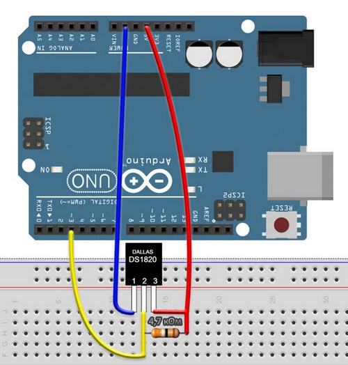
In order to properly connect the sensor to the Arduino system, it is necessary to act in accordance with the following algorithm:
- The black contact of the temperature sensor must be connected to the Arduino GND system.
- The red contact of the temperature sensor must be connected to + 5V of the Arduino system.
- The red contact of the temperature sensor can be connected to any free digital pin in the Arduino system.
- Connect a 4.7 kilo ohm resistor to the external piping system.
The full diagram of connecting the DS 18B20 temperature sensor to the Arduino Processing LCD system is shown in the image below.
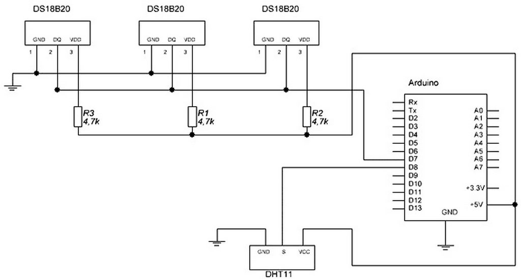 Connection diagram of temperature sensors DS 18B20 to the Arduino system
 Installing the OneWireLibrary database
After successfully downloading the archive with the database to your computer, you need to import it into the Arduino system. In the program's control panel, select the following items: Sketch - “Import database” - “Add database”. After this, select the archive you downloaded to your personal computer. If you encounter unforeseen difficulties while importing a database into the system, you should read more carefully the instructions for managing databases in Arduino.
Download the sketch to the system
As a rule, the desired sketch is always in the “examples” category in the OneWireLibrary database. You need to go to the program's control panel using the following algorithm: “File” - “Examples” - OneWire and select an example that will contain the name of the temperature sensor to be connected.
This function is used to ensure that the database can receive information about all temperature sensors DS 18B20 and be displayed on the monitor of the Arduino system.
What type of food to choose
It is imperative to make sure that the pin names you entered are correct.
 Connect the DS18b20 temperature sensor to the Arduino program
 How to connect multiple DS 18B20 temperature sensors at the same time
Connecting several DS 18B20 temperature sensors to an Arduino Processing LCD is possible. This is provided by the OneWirelibrary database, which can read all information from all connected devices at the same time.
If we are talking about connecting a large number of sensors (for example, if there are more than 10), resistors with a lower resistance value (for example, 1.5 kilo or less) should be used.
If you are going to connect more than a dozen sensors DS 18B20, there may be problems with their accuracy. In this case, you can install a resistor (resistance is approximately 100 ohms) between the white contact on the Arduino machine and the white contact on each sensor.
In this article we will tell our readers how to connect temperature sensors. DS18B20, LM35 and TMP36on the circuit board Arduino unowhich is built on a microcontroller ATmega328. The main purpose of the temperature sensors DS18B20, LM35 and TMP36 is temperature readings. In our case, the temperature readings from these sensors will be read by the Arduino UNO printed circuit board, and output the result on a computer screen. In fact, using these sensors, anyone can create their own thermometer. In addition to a detailed description of the use of Arduino UNO and DS18B20, LM35 and TMP36 sensors, we will tell our readers where to buy these components.
We prepare the software on the PC using the Arduino IDE
If you already have an Arduino UNO board and the sensors under consideration, then it is time to configure the computer so that it can work with the microcontroller. For this task, we will need the Arduino IDE software package. Download this package on the official website www.arduino.cc. At the time of this writing, the latest version of the package is ARDUINO 1.6.10. We will use IDE on a PC with Windows 10 operating system. After downloading the IDE, we will launch the installation file.
In the initial window of the installer, we accept the terms of the license agreement and proceed to the next window.
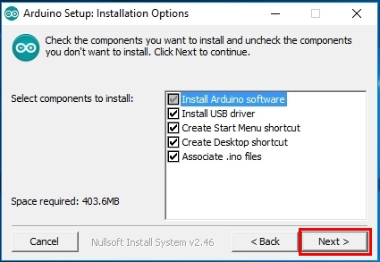
In this window, leave everything as it is and continue the installation by clicking the " Next\u003e».
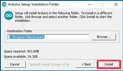
In this window, you can choose the installation path for the Arduino IDE, in our case it is the default folder. Selecting the path, press the button " Install, Which will start the installation process.
After the installation is complete, a shortcut will appear on your desktop named Arduino.
As you can see from the example, the installation of the Arduino IDE is not much different from the installation of other programs, the only thing that can confuse the user is the English interface.
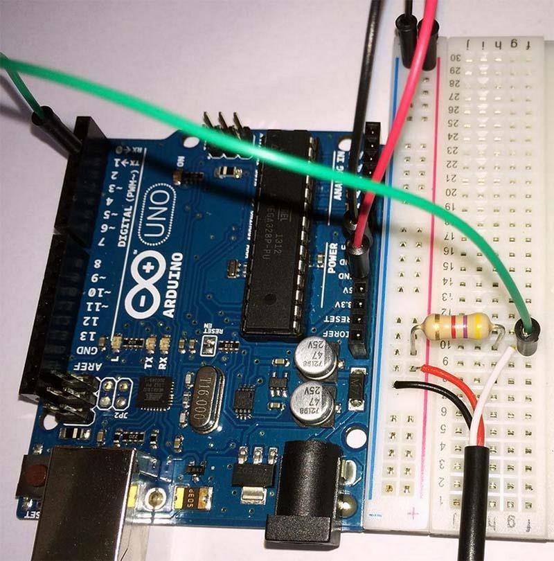
We connect the DS18B20 sensor to the Arduino UNO board
First thing we need to plugmyself sensor to board. For this we need breadboard and resistor with a resistance of 4.7 kΩ. Below is the wiring diagram of the sensor in question. DS18B20 to Arduino uno.
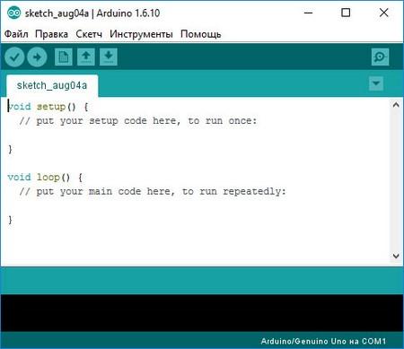
Connect the board to the computer via USB cable. After connecting, the board should light up the LED called " ON". Now we need open previously installed Arduino IDE through the shortcut on your desktop.
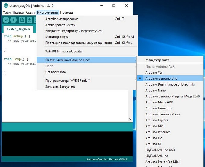
In the open program window, go to the menu “ Instruments"To item" Pay: ”And choose our fee.
To make our sensor work, we need load library « DallasTemperature», Which can be downloaded from this link arduino-project.net/DallasTemperature.rar. After loading the library, it needs to be connected to the IDE. To do this, unzip the downloaded library into the library directory, which is located at the address “C: \\ Program Files \\ Arduino \\ libraries”. You can view the connected library in the menu “ Sketch».
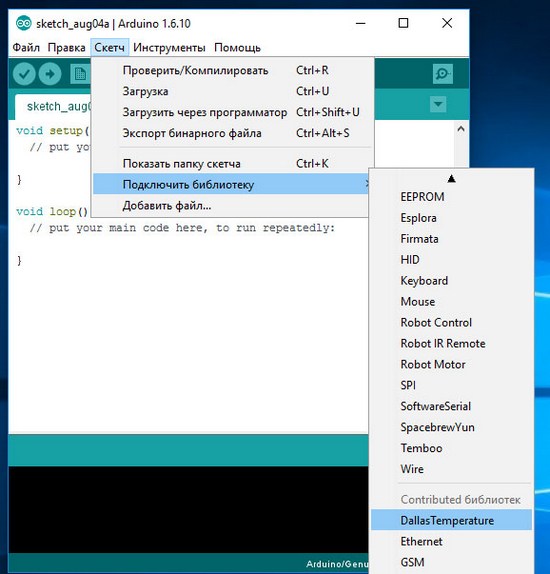
Now let's execute an example from the connected library. To do this, follow the links " File» - « Examples» - « DallasTemperature» - « Multiple". After this action, the example chosen by us will be loaded into the program window.
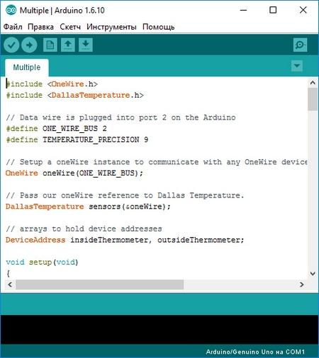
Now load this example into the Arduino UNO board using the "" button. Thereafter open item « Port monitor", Which is in the menu" Instruments».
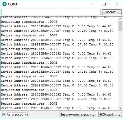
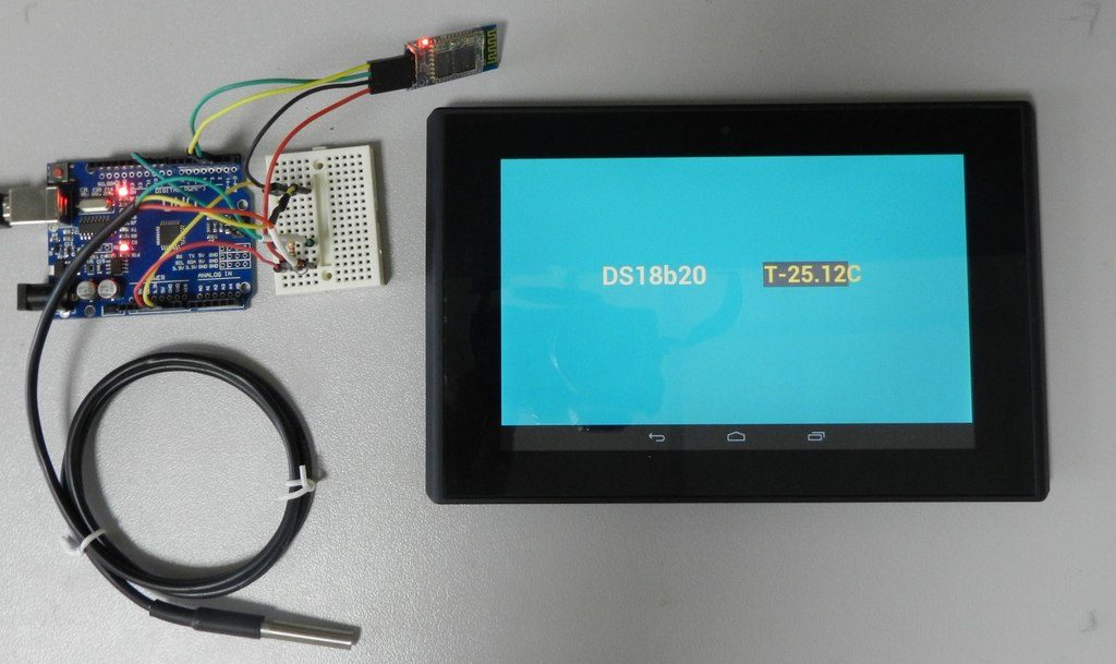
From the monitor you can see that our DS18B20 sensor shows the temperature, both in Celsius and Fahrenheit.
We connect the LM35 sensor to the Arduino UNO board
temperature sensor LM35 is an inexpensive model that the company produces Texas Instruments. This sensor is quite easy to connect to the Arduino UNO. Below is a diagram of the connection of the considered sensor to the printed circuit board.
From the diagram it is clear that the sensor LM35 connects directly without using a resistor. Now we type in a fairly simple code shown in the IDE below.
After downloading this code to the board, open “ Port monitor"And see how the sensor takes temperature readings from the place where it is located.
From the example it can be seen that the LM35 sensor is much easier to connect to the Arduino UNO than the one considered earlier.
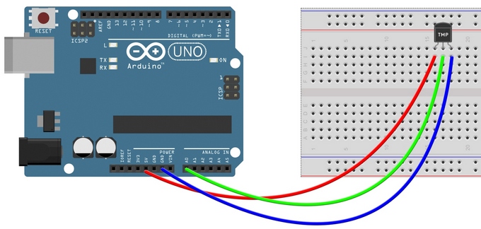
We connect the TMP36 sensor to the Arduino UNO board
temperature sensor TMP36 is a budget model of the company Analog devices. Since for this example we did not have the sensor itself, we used the Internet service that allows us to emulate Arduino boards. This example will be especially interesting to those users who want to try the Arduino before purchasing it. To get to the Autodesk Circuits service, you need to go to https://circuits.io. On this page you need to go through the quick registration procedure, after which you will be taken to home page service.

To create a new project, you must press a button « New electronics lab" on this page. After this action we will get to the project window.
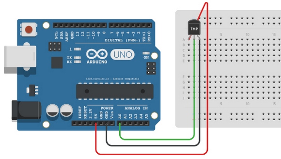
From the project window it is clear that we have only a breadboard. To add the components we need open the panel « Components". From this panel, we add and connect the components, as shown in the image below.
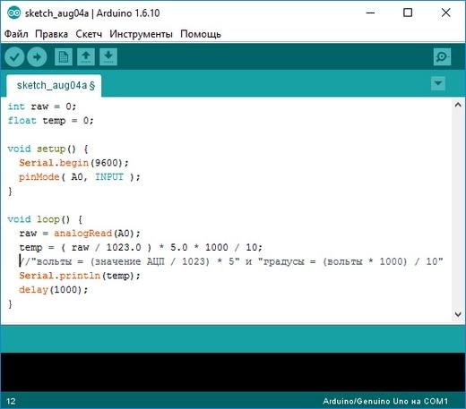
After building the package go to the panel « Code Editor"And insert textpictured below.
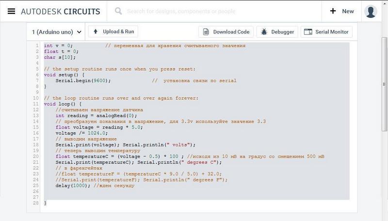
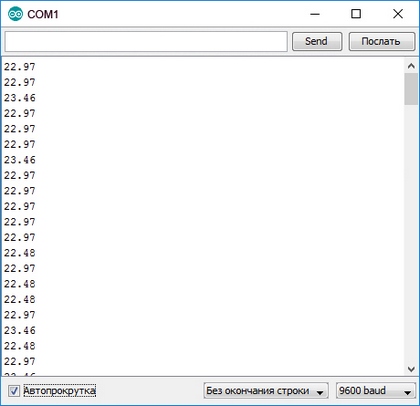
Also note the code. It contains descriptions of the functions of all operations. Now try to run our fee. For this press the button « Start simulation“, Then we will see how the green LED lights up. To verify that our project is working, we let's open « Serial monitor».
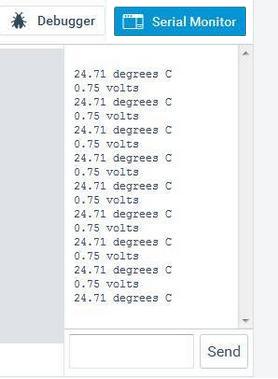
From the monitor window, you can see that our virtual sensor measures temperature readings.
From the example, it is clear that to make a project with a TMP36 sensor in Autodesk Circuits is a snap. We strongly recommend beginners to use the emulator before actually using the Arduino UNO and components.
If you incorrectly assemble any scheme, then you can actually burn both the Arduino UNO board and its components. By the way, in Autodesk Circuits you can also burn a PCB, albeit a virtual one.
Where to get the Arduino components to measure the temperature
Many more than once thought about buying Arduino and additional details to it. But the deterrent of such a purchase has always been a fairly overpriced price, which is represented in the domestic market. To save our readers, we recommend buying all Arduino components and boards in China. One of the most popular Chinese online stores is AliExpress.com. On this site you can find almost any component and fee Arduino. Below is a list of the parts that we used in the article:
- The DS18B20 temperature sensor costs $ 0.7;
- The LM35 temperature sensor costs $ 0.8;
- Temperature sensor TMP36 costs $ 3;
- An Arduino UNO PCB costs about $ 3.
From the list we can summarize that the Arduino UNO bundle plus DS18B20 is the most profitable offer.
Summarize
In this article, we looked at two examples of connecting physical sensors measuring the DS18B20, LM35 to an Arduino UNO printed circuit board. In addition, we have considered a variant of the virtual assembly of the circuit using the TMP36 sensor. In all the examples we presented the output of temperature indicators only through “ Port monitor". This was done specifically to make the assembly scheme as simple as possible. In the open spaces of the network you can find hundreds of examples where you can use these connection options:
- Transformation of a smartphone into a thermometer, thanks to the removal of temperature readings on its screen or PC from various sensors using the Wi-Fi module for Arduino;
- Transformation of a smartphone into a thermometer, due to the removal of temperature indicators on its screen or PC from various sensors using the Bluetooth module for Arduino;
- Creating a thermostat with LED display;
- Creating a thermometer based on Arduino and TFT display;
- Get temperature readings with Arduino over the Internet.
This is only a small fraction of the examples by which the user can get temperature indicators through the Arduino board. Using Arduino, in our time, everyone can translate into reality the concept of a smart home. We hope our material will be useful for you, and thanks to it, you can connect temperature sensors to your Arduino board.