How best to connect. Reliable ways to connect electrical wires
When wiring or repairing electrical wiring, when connecting household appliances and a lot of other work, it is required to connect the conductors. In order for the connection of wires to be reliable and safe, it is necessary to know the characteristics of each of them, where and when, under what conditions they can be used.
Existing ways of connecting conductors
To connect wires can be done in several ways:
- welding is the most reliable method that provides high reliability of the connection, but requires skills and the presence of a welding machine;
- terminal blocks are a simple feasible and fairly reliable connection;
- soldering - works well if the currents do not exceed the standard and the connection does not heat up to temperatures above normal (65 ° C);
- crimping with sleeves - requires knowledge of technology, special pliers, but the connection is reliable;
- the use of spring clips - wago, PPE - are quickly installed, provided that the operating conditions are observed, they provide good contact;
- bolted connection - simple to perform, usually used in difficult cases - when it is necessary to switch from aluminum to copper and vice versa.
The specific type of connection is selected based on many factors. It is necessary to take into account the material of the conductor, its cross-section, the number of cores, the type of insulation, the number of conductors that will be connected, as well as the operating conditions. Based on these factors, we will consider each of the types of connections.
Welding - high reliability in all conditions
When the wires are connected by welding, the conductors are twisted, and their end is welded. As a result, a metal ball is formed, which ensures a stable and very reliable connection in all conditions. Moreover, it is reliable not only in terms of electrical characteristics, but also mechanically too - the metal of the connected wires after melting forms a monolith and it is impossible to isolate a separate conductor.

Welding - it is important to heat the metal, but not melt the insulation
The disadvantage of this type of wire connection is that the connection is 100% one-piece. If you need to change something, you need to cut off the fused piece and redo it all over again. Therefore, for such connections, a certain supply of wires is left - in case of possible rework.
Other disadvantages include a welding machine, appropriate electrodes, flux and work skill. In addition, welding takes a lot of time, it is required to protect the surrounding objects, and it is also inconvenient to work with the welder at a height. Therefore, electricians practice this type of connection in exceptional cases. If you do "for yourself" and know how to handle the welding machine well, you can practice on scraps. The main trick is not to melt the insulation, but to weld the metal.
After cooling, the welding site is insulated. You can use electrical tape, you can use heat shrink tubing.
Crimping wire connection
For crimping wires, a special aluminum or copper sleeve is required - it is selected based on the size of the twist (diameter of the bundle), and the material is taken the same as that of the conductors. Bare and shiny wires are twisted, a sleeve tube is put on them, which is clamped with special pliers.

Both sleeves and pliers are different, there are several types. Each of them has its own rules of use (the number of wires that can be packed in a sleeve), in which you need to be well oriented. It is necessary to pack the wires according to certain rules, measure the size of the resulting bundle, and adjust it to the requirements. In general, a rather dreary task. Therefore, this type of wire connection is mainly used by professional electricians, and more and more often they are switching to spring clips.
Terminal blocks
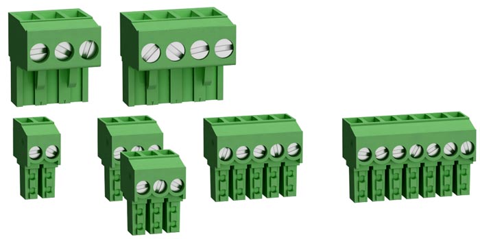
One of the simplest and most reliable wire connections is through terminal blocks. There are several types of them, but a screw connection is used almost everywhere. There are sockets of different sizes - for different sizes of conductors, with a different number of pairs - from 2 to 20 or more.
The terminal block itself is a plastic case in which a metal socket or plate is soldered. A bare conductor is inserted into this socket or between the plates, clamped with a screw. After the screw is tightened, you need to tug the conductor well - make sure that it is tightly clamped. Due to the fact that the connection points remain uninsulated, the area of \u200b\u200bapplication of the terminal blocks is in rooms with normal humidity.
The disadvantage of such a connection: due to the plasticity of metals - especially aluminum - contact weakens over time, which can lead to an increase in the degree of heating and accelerated oxidation, and this again leads to a decrease in contact. In general, periodically, the wiring in screw terminal boxes must be tightened.

Advantages - speed, simplicity, low cost, does not require any skills, except that the ability to use a screwdriver. Another important advantage is that you can easily connect wires of different diameters, single-core and multi-core, copper and aluminum. There is no direct contact, therefore there are no risks.
Soldering
First, about the soldering technology. The connected conductors are cleaned of insulation, cleaned from oxide film to pure metal, twisted, then tinned. For this, the conductors are heated with a soldering iron and applied to the rosin. It should cover the joint completely. Tinned wires are twisted first with your fingers, then squeezed using pliers. Soldering flux can be used instead of tinning. They wet the wires well, but after twisting.
Then, in fact, the soldering process begins: the joint is heated with a soldering iron or a narrow-torch torch. When the rosin or flux begins to boil, they take some of the solder on the tip of the soldering iron, bring it into the soldering zone, pressing the tip to the conductors. The solder flows to fill the gaps between the wires, ensuring a good connection. When using a torch, the solder is simply added a little to the torch.
Further, after the soldering point has cooled down, according to the technology, it is necessary to wash off the flux residues (they accelerate oxidation), dry the connection, cover it with a special protective varnish, and then isolate it with electrical tape and / or heat shrink tubes.
Now about the advantages and disadvantages of this method of connecting wires. In low current systems, soldering is one of the most reliable ways to connect wires. But, when wiring electrical wiring in a house or apartment, it is criticized mercilessly. The thing is that the solder has a low melting point. With periodic passage of large currents through the connection (it happens if the protective circuit breakers are incorrectly selected or faulty), the solder gradually melts and evaporates. Over and over again the contact gets worse, the connection heats up more and more. If this process is not found, it may well end in fire.
The second negative point is the low mechanical strength of the soldering. It's about tin again - it's soft. If there are a lot of wires in the soldered joint, and if they are still rigid, when trying to pack them, the conductors often fall out of the solder - the elastic force is too great, which pulls them out. Therefore, it is not recommended to use the connection of conductors by soldering when wiring electricity: it is inconvenient, long and risky.
Spring clamps for connecting wires
One of the most controversial ways to connect wires is with spring clips. There are several types, but the most common two are wago (wago) terminal blocks and PPE caps. Externally and in the way of installation, they are very different, but at the heart of both designs is a spring that creates strong contact with the wire.
About this spring and there are disputes. Opponents of wago use say that the spring will weaken over time, the contact will get worse, the connection will start to get hotter, which, again, leads to an even faster decrease in the degree of spring elasticity. After some time, the temperature may rise so much that the body (plastic) will melt, but what can happen next is known.

Spring loaded wiring clamps - popular wire connection
In defense of the use of spring clips to connect wires, it can be said that if they are used in accordance with the manufacturer's recommendations, problems are very, very rare. Although there are many fakes and wago, and PPE, as well as an abundance of photos of them in molten form. But, at the same time, many people use them, and, under normal operating conditions, they work for years without any complaints.
Wago wire clips
They appeared on our market several years ago and made a lot of noise: with their help, the connection is very quick and easy, and at the same time has high reliability. The manufacturer has specific recommendations for the use of these products:

There is a metal plate inside these devices, which ensures the proper degree of contact. The shape and its parameters of the plates were specially developed and tested. The tests were carried out on a vibration stand for many hours, then heated and cooled. After that, the electrical parameters of the connection were checked. All tests were passed with "excellent" and branded products always show themselves "five".
In general, the range of Wago products is very wide, but for wiring or connecting home appliances, lighting fixtures, they use two options for wire clamps: 222 series (detachable) with the ability to reseal or change the connection and 773 and 273 series - which are called one-piece.
Detachable
Spring clips for wiring Wago 222 series has a number of contact pads - from two to five - and the same number of flag-clips. Before starting the connection, the flags go up, the conductors stripped from insulation are inserted into them (all the way), after which the flag is lowered. At this point, the connection is considered complete.

Wago wire connectors - connection methods
If necessary, you can reseal the connection - raise the locking flag and remove the conductor. Convenient, fast and reliable.

The 222 Vago series can be used to connect two or three, even five conductors made of copper or aluminum (you can connect different metals in one terminal). Wires can be solid or stranded, but with stiff wires. The maximum section is 2.5 mm 2. Soft stranded wires can be connected with a cross section of 0.08 mm 2 to 4 mm 2.
One-piece
There is another type of clamps, which does not provide for the possibility of remaking the wire connection - the 773 and 273 series. When using these clamps, the work is generally a second: the stripped wire is inserted into the corresponding socket. There is a spring clamping it, ensuring contact with the plate. All.

These spring loaded wire clamps can be used to connect solid aluminum or copper wires with a cross-sectional area of \u200b\u200b0.75 mm 2 to 2.5 mm 2, stranded with rigid wires from 1.5 mm 2 to 2.5 mm 2. Soft stranded conductors cannot be connected with these connectors.

To improve contact, the wires must be cleaned of oxide film before connecting. To prevent further oxidation from continuing, wago manufacturers also produce contact paste. The inside of the clamp is filled with it and it itself corrodes the oxide film, and then protects the wires from oxidation in the future. In this case, only highly oxidized, dark conductors need preliminary stripping, and the clamp body is filled with paste.
By the way, manufacturers say that, if desired, the wire can be pulled out of the clamp. To do this, take the wire with one hand, hold the terminal box with the other and rotate them back and forth with a small range, in opposite directions, stretching in different directions.
Clamps for lamps (construction and installation clamps for luminaires)
For quick and convenient connection of lamps or sconces, wago has special 224 series terminals. With their help, it is possible to connect aluminum or copper wires of different cross-sections and types (single-core or stranded with rigid wires). The nominal voltage of this connection is 400 V, nominal current:
- for copper conductors - 24 A
- 16 A for aluminum.

Cross-section of the connected conductors from the mounting side:
- copper 1.0 ÷ 2.5 mm2 - single-core;
- aluminum 2.5 mm2 - single core.
Cross-section of the connected conductors from the side of the chandelier / sconce: copper 0.5 ÷ 2.5 mm2 - single-core, multicore, tinned, crimped.
When connecting copper wires, contact paste must be used, and aluminum wires must be manually stripped to bare metal.
This product has two drawbacks. First, the price of original terminals is high. Second - there are a lot of fakes at a lower price, but their quality is much lower and it is they who burn and melt. Therefore, despite the high cost, it is better to buy original products.
PPE caps
PPE caps (stands for “connecting insulating clamps”) are very easy-to-use devices. It is a plastic case with a conical spring inside. Conductors stripped of insulation are inserted into the cap, the cap is rotated clockwise several times. You will feel that it has stopped scrolling, which means the connection is ready.

How to make a wire connection using PPE
These conductor connectors are produced by many manufacturers, they are available in different sizes, for different diameters and the number of conductors to be connected. In order for the connection of the wires to be reliable, the size must be chosen correctly, and for this it is necessary to understand the marking.
After the letters PPE there are several numbers. Depending on the manufacturer, the number of digits changes, but they mean the same things. For example, there is this type of marking: SIZ-1 1.5-3.5 or SIZ-2 4.5-12. In this case, the number immediately following the letters indicates the type of case. "1" is set if the body is an ordinary cone, on the surface of which grooves can be applied - for a better grip. If there is a CIZ-2, then there are small protrusions on the body, which are convenient to grasp with your fingers and twist.
All other numbers reflect the total cross-section of all conductors that can be connected using this particular PPE cap.

For example, PPE-1 2.0-4.0. This means that the body of the connecting cap is conventional, conical. It can be used to connect two conductors with a cross section of at least 0.5 mm 2 (they add up to 1 mm, which meets the minimum requirements - see the table). This cap contains maximum conductors, the total cross-section of which should not be more than 4 mm 2.

Connection of wires with PPE caps
In the second version of the marking, after the abbreviation PPE, there is only a number from 1 to 5. In this case, you just need to remember which one is useful for which wire cross-section. The data is in another table.

PPE caps and their parameters
By the way, PPE caps can only connect copper wires - aluminum conductors, as a rule, are thicker than the maximum allowable for these connectors.
Bolted connection
This connection is assembled from a bolt of any diameter, a suitable nut and one, or better - three, washers. It is assembled quickly and easily, it serves for a long time and reliably.

First, the conductors are stripped of insulation; if necessary, the upper oxidized layer is removed. Further, a loop is formed from the stripped part, the inner diameter of which is equal to the diameter of the bolt. To make it easier, you can wrap the wire around the bolt and tighten it (middle version in the right figure). After that, all this is collected in this order:
- A washer is put on the bolt.
- One of the guides.
- The second washer.
- Another conductor.
- Third puck.
- Nut.
The connection is tightened first by hand, then using keys (you can take pliers). That's all, the connection is ready. It is mainly used if it is necessary to make a connection of wires from copper and aluminum, it can also be used when connecting conductors of different diameters.
How to connect aluminum and copper conductors
By the way, let us remind you why you cannot directly connect copper and aluminum wires. There are two reasons:
- Such a connection gets very hot, which in itself is very bad.
- Over time, the contact weakens. This is because aluminum has a lower electrical conductivity than copper, as a result, when passing the same currents, it heats up more. When heated, it expands more, squeezing out the copper conductor - the connection gets worse, it heats up more and more.
To avoid such troubles, copper and aluminum conductors are connected using:
- terminal blocks;
- wago;
- bolted connection;
- branch clamps (make wire connections on the street).
Other types of connectors cannot be used.
How to connect wires of different diameters
If conductors of different diameters are to be connected, no twisting should be present to obtain good contact. This means that you can use the following types:
- terminal blocks;
- wago;
- bolted connection.
We will send the material to you by e-mail
Grandfather's methods of primitive twisting of wires with obligatory insulation with the notorious blue tape are long gone. requires a professional approach, which means you need to use materials and devices that meet not only the highest safety requirements, but also simplicity, reliability and attractive appearance. One such device is wire connection terminals. Today we will talk about how to choose and use them correctly.
Small terminal - the solution to many wiring problems
How the two wires are connected depends on many factors. Consider the metal of the conductor, the thickness of the wiring, the number of cores and the type of insulating material. An important factor is the conditions in which the connection will be operated.
There are several main types of connections:
Let's consider in detail the main characteristics of all these compounds.
Features of professional twisting
Twisting is the simplest method of connecting wiring. No special tools are required for work, a knife and pliers are enough. To make the connection strong, experts recommend stripping the cores by at least 5 cm. To make the contact tight, the wires are clamped with pliers and twisted with a rotational motion. After the resulting connection is wrapped in one direction and tightly wrapped with electrical tape. This is the simplest option for such a connection.
Professional electricians have other ways to twist wires together:

Important! If you use electrical tape, do not skimp on the winding. The insulation should cover not only the twist itself, but also go over the wires by at least a couple of centimeters.
Instead of electrical tape, you can use modern material - heat shrink tubing. Before connecting the conductors, the heat shrinkage of the required length is put on one of the wires and then pulled over the twist. It remains only for a moment to bring a match or a lighter to the tube, it will shrink and tightly fix and insulate the veins.

With reliable insulation, such a connection will last long enough. Its advantage is good vibration resistance, which is good for moving machinery. Electricians do not recommend using this method when connecting wires of different sizes. During operation, excessive resistance heats up the contact point so that the insulating layer can melt. Professionals do not advise twisting wires with conductors of different metals and cables with a large number of conductors.
Soldering for perfect conductivity
Not only the perfect operation of the mechanism, but also the safety of its user depends on the reliability and strength of the connection of the conductors. Soldering is one of the most reliable types of connection.

There is a soldering iron in almost every home, and the procedure itself does not take much time
Rosin is used for tinning, and tin or other fluxes are used as solder. Copper wires are recommended to be soldered with tin or lead, aluminum - with zinc-tin, aluminum or copper compounds. Before soldering, the wires are stripped and twisted using one of the above methods. After that, rosin and flux are applied to the twisting place with a soldering iron.
Important! The heated solder should fill in all the irregularities and holes in the twist.
After soldering, the connection is insulated with tape or heat shrink. The hardest part is soldering aluminum wiring. It oxidizes rapidly at high temperatures and does not form a strong bond with the solder material. For a strong connection, you need to use tinning.
If the soldering is done correctly, the contact should be good. The only drawback is the fragility of the connection; under vibration and mechanical loads, it will not last long.
For professionals: welding
Welding allows the metal of the conductors to fuse and provide optimal resistance. This contact is strong and durable.

Arc, spot, torsion, plasma, ultrasonic and beam welding can be used.
Such work requires experience and dexterity, so the welding method is the tool of professional electricians. They use graphite and carbon electrodes, are stationary, and use high precision voltage controlled inverters. This technique is not suitable for domestic conditions, only experienced welders know how to properly connect the wires to each other in such a complex way.
Important! All welding work must be carried out in a protective helmet. It will be very difficult for a beginner to achieve a high-quality connection of conductors.
After welding, the contact point is also insulated with tape or heat shrinkage.
Crimping with sleeves
Returning to the ways of connecting wiring more accessible for domestic use, it should be noted that crimping is a simple and affordable method that can be used without special skills.

The technique is very simple - conductors of wires are inserted into a metal sleeve and then the soft metal is crimped using pliers or a vice. It is best to use special pliers for this purpose. They can manually crimp sleeves with a cross section of up to 120 mm². If a larger liner is required, use hydraulics. The disadvantage of a sleeve connection is that it is final, and, if necessary, it will not work to correct the contact without cutting the wire.
For your information! For crimping, select sleeves of the appropriate material to ensure optimal contact. There are sleeves made of aluminum, copper and alloys. The cross-sectional diameter of the conductor is also taken into account, the cores must fit tightly into the sleeve.
The use of terminal blocks for connecting wires
The easiest to use and at the same time reliable is installation using terminal blocks.

Terminal clamps for wires can be used when mounting conductors from different metals. At the same time, the design of the terminals avoids direct contact between aluminum and copper and the formation of corrosion inevitable for such a connection.
Terminal blocks are divided into three main types: knife, screw and spring. As a rule, a brass alloy is used as the base material. Some models are filled with a gel that protects the contacts from corrosion.
Standard requirements for terminal strips
Like any electrical component, the terminal block has developed standards of reliability and quality:
| Demand | Description |
|---|---|
| Heat resistance | The terminal body material must be able to withstand high temperatures and be free from any risk of ignition. The body must not deform when heated, and the protective cover is not made of flammable material. |
| Strong hold | The terminal blocks must be secured without undue effort and, at the same time, securely hold the wire strands. In this case, the conductors do not need to be additionally processed or twisted. |
| Corrosion resistant | The contact plates in the terminals are of such a length that direct contact between the conductors is excluded. In this case, even if the wires are made of different metals, there will be no electrochemical corrosion. |
| Informativeness | Each connector for electrical wires contains information about the diameter of the conductors and the permissible voltage in the mains. |
Pros and cons of terminal switching
As with any device, terminal connections have their advantages and disadvantages. First about the benefits:
- Easy to connect. The terminals can connect two or more wires with different cross-sections and metal, while each core is placed in a separate socket and, if necessary, can be easily separated. If welding, jacket or soldering were used for switching, you would have to remove the insulation, break or unscrew the contacts and then repeat the switching procedure again.
- Security. The terminals are made of insulating material. Even if you accidentally touch the switching point, you will not receive an electric shock.
- There is no need to use a special tool. For the screw connection, you only need a suitable screwdriver.
- Reliability of fastening. The junction of the wires is resistant to mechanical and temperature stress, vibration and stretching.
- Aesthetics. Connecting wires with clamps looks much neater than winding electrical tape.

Disadvantages of clamping connections:
- Cost. The price of a high-quality terminal is 10 ÷ 12 rubles per piece. If you just need to connect a pair of wires in the chandelier, this is not essential. But with a set of terminal contacts, it can cost a lot. But this drawback is a matter of time. A lot of competition in this market and the development of new technologies will soon make these devices cheap.
- Some difficulties in installation in hard-to-reach places. If you need to install the terminal block in a place where it is difficult to reach your hand or fingers, the task may seem too difficult. On the other hand, it is not easy to perform any other switching in such a place.
How to choose terminals for connecting wires
To choose the right terminal, first of all, you should study the cable that you plan to connect. You need to find out, it is usually indicated in the marking of the wire.
The second selection criterion is high-quality terminal material. It must be rigid enough and have reliable insulation. It is better if the screw and bracket of the device are made of steel. The terminals must be compact. It is possible that you will have to place the contact group in a limited space, so the size of the connections will matter.

Another criterion for making the right choice is ease of installation and maintenance. The terminals with a guide cone and a flag marking the place of conductor entry are especially convenient in operation.
Important! For terminals with a small cross-section up to 16 mm², the insulation is installed on one side, so you need to be very careful when installing them, otherwise a short circuit may occur.
Convenient if the surface of the terminal is suitable for marking. Sometimes it is necessary for the further operation of the connection.

Types of terminal contacts
Modern manufacturers offer a wide range of switches for performing connections of various purposes. Each model meets certain tasks and requirements, we will consider them in more detail.
Screw switches
These simple and reliable devices are ideal for installation in wall outlets and similar locations. The cores are fixed in the terminal with screws.

For your information! Lead and copper switches can be used to connect the car battery. Auto mechanics recommend giving preference to lead fasteners. They do not oxidize as much as copper ones when exposed to acid.
Screw terminal blocks are not used for aluminum wiring. This is due to the fact that the aluminum conductor collapses under the pressure of the screw fastener. If provided in the switch, the head of the screw is marked with green paint.
Terminal clamps for wires
The design of such switches involves the use of a small spring that fixes the core in the desired position.

Such terminal blocks are installed in an instant: the stripped wiring is simply inserted and fixation is carried out in one click.
Junction Box Switches
Such terminals are used to connect wires in junction boxes. The switch body is made of polycarbonate and the contact point is made of copper. Springs are used to fix the cores.

For reliability, the terminals are treated with a special paste that protects the contacts from overheating.
Video on how to properly connect wires in a junction box using terminals
Fuse Terminals
A separate type of switches is with a built-in fuse. Such contact groups additionally protect the wiring from short circuits.

Such wagons for connecting wires take up more space than conventional terminal blocks and are used in cases where electrical appliances do not have built-in fuses in their design.
Connecting pads
Pads are a handy gadget for connecting multiple wires. Brass tubes with threaded holes are placed in the body of such a device. With the help of such small devices, it is possible to connect copper and aluminum wires to each other, as well as conductors of different cross-sections.
Switching in the block occurs in such a way that the conductors do not contact directly. The only thing that you should pay attention to is the indicator of the rated current on the block itself.
Blade terminals
These switches are also called wire crimp terminals. They are used for power conductors with a small cross-section up to 2.5 mm. The maximum voltage for such a connection is 5 kV. Such a connection will not withstand a more powerful current, so knife terminal blocks are not used in large power plants.

Which terminal blocks are better
In fact, choosing the right terminal should be taken very seriously. Especially if there is a need to connect wires with conductors of different metals. During operation, such contacts get very hot and deformed. This can lead to a complete loss of circuit integrity and even a short circuit. It is worth remembering that spring and screw terminal blocks are not suitable for fastening aluminum and copper wiring.
A few words about switch manufacturers
On the shelves of electrical goods stores, products from European, Chinese and domestic manufacturers are presented. As a rule, few ordinary buyers are puzzled by the origin of switches. And in vain. These tiny, fingertip-sized devices can directly affect the safety of your property. Do not blindly trust Chinese consumer goods. In most cases, China's products do not meet the requirements of domestic standards.

Domestic products are more reliable, but less aesthetic and technological. European goods are more expensive, but I bought such a terminal and forgot. Manufacturers guarantee long-term and reliable performance of their products. Here is some of them:
LEGRAND
Screw switches from this manufacturer are the most popular product in this category. Brass products are nickel-plated and can reliably withstand extreme temperature changes. Such terminals are characterized by high strength and a wide range of sizes.

WAGO
The products of the French company guarantee a strong connection of wiring of different types and cross-sections. The devices perfectly resist possible vibration and stretching and are installed without special tools. The main material of French terminal blocks is tin-plated copper, which gives good contact with low resistance. Some models are filled with anti-corrosion gel.

PHOENIX CONTACT
The German manufacturer is distinguished by excellent product quality. It offers over 200 kinds of different switches for different types of connections. Among the models presented there are those that are resistant to high humidity and explosion hazard.

WIEDMULLER
Another European brand offers one and a half hundred terminal models. The assortment is based on DIN screw connections.

Common problem: how to connect aluminum and copper wire
Residents of Soviet-built houses often face such a task. At that time, almost all wiring was done with aluminum conductors. Modern electricians mostly use copper wire. How to connect aluminum to copper wire? There are skeptics who argue that such a connection is impossible. You shouldn't believe them. If you correctly use the techniques that we will give below, the switching will be reliable and durable.
As already mentioned, ordinary twisting will not work for such a connection. The contact between copper and aluminum is very hot and can damage the insulation layer.
Option 1 - bolted
This is a simple and affordable method using a steel nut, bolt and washer. Due to the impressive dimensions of such fasteners, it is unlikely that it will be possible to place it in a modern small junction box. But on the other hand, such switching allows you to combine wiring not only from different metals, but also with different sections. These connections are easy to disassemble and assemble when needed.
Option 2 - nut connection
The name of such a connection was invented by electricians because of the external similarity. For fasteners, a special crimp is used, which is sold in electrical stores. The device consists of two dies with grooves for conductors. After fixing the cores, the dies are wrapped with electrical tape.
Electricity is not an area where you need to save money. It is advisable to do everything carefully, to select high-quality materials, to approach the choice of sizes / diameters / ratings carefully. To begin with, even connecting the conductors must be correct. And choosing ways to connect wires is not nearly as easy as it seems.
There are about a dozen ways to connect wires. In general, they can be divided into two groups: those that require special equipment or specific skills and those that any home craftsman can successfully use - they do not require any special skills.
The first group includes:
- Soldering. When connecting wires of small diameter in the amount of 2-3 pieces, it is a very reliable method. True, it requires a soldering iron and some skills in using it.
- Welding. We need a welding machine and special electrodes. But the contact turns out to be reliable - the conductors are fused into a monolith.
- Crimping with sleeves. We need sleeves and special pliers. Liners are selected according to certain rules that you need to know. The connection is reliable, but you will have to cut it to reseal it.
All these methods of connecting wires are performed mainly by specialists. If you have the skills to handle a soldering iron or a welding machine, after practicing on unnecessary trimmings, you can do them yourself.

Some ways of connecting wires are more popular, others less
Wiring methods that do not require any specific skills are becoming more and more popular. Their advantage is quick installation, reliable connection. Disadvantage - "connectors" are needed - terminal blocks, clamps, bolts. Some of them cost quite decent money (Wago terminal blocks, for example), although there are also inexpensive options - screw terminal blocks.
So here are the ways to connect wires, which are simple to execute:

There are two opposing opinions among professionals. Some believe that new ways of connecting wires - clamps - are the best way out, since they speed up installation without compromising the quality of the connection. Others say that someday the springs will weaken and the contact will deteriorate. In this matter, the choice is yours.
Technical nuances of different types of wire connections
All the types of wire connections described above are used when laying electrical wiring, but a specific type is selected based on several characteristics:

Consider each connection method, the technology for its implementation and the feasibility of using it in various situations.
Soldering electrical wires
One of the oldest and most widespread types of compounds. To work, you will need rosin, solder and a soldering iron. The soldering process is as follows:

Actually, this is where the soldering of electrical wires is completed. Not the most difficult process, but it requires certain skills. The main thing is to warm up the junction enough so that the solder flows between all the wires. In this case, it is impossible to overheat, otherwise the insulation will melt. This is the art - not to burn the insulation, but to provide a reliable contact.
When can soldering be used? This method of connecting wires works well in low-current electrics. When connecting wires in a junction box, it is no longer very convenient. Especially if there are a lot of wires and / or they are of large diameter. Soldering such a twist is not a task for beginners. In addition, when trying to lay the joint in the junction box, the soldering begins to break. Up to the point that some wires fall off. In general, the method is good for connecting small diameter conductors.
Welding conductors in electrical connections
One of the most reliable ways to connect wires is welding. During this process, the metal of the individual conductors is brought to the melting point, mixed, and after cooling it is a monolith. This method works very well with large diameters or with a large number of conductors to be connected. It is distinguished not only by excellent contact, which does not weaken over time and does not change its characteristics. It is also mechanically very strong - the fused part does not allow the joint to fall apart even under heavy loads.

Drop at the end of the twist - molten aluminum
There are also disadvantages. The first is precisely that the conductors are fused, that is, the connection is completely one-piece. If you need to repack it, you have to remove the fused part and start everything anew. To be able to do this, you always need to leave a small reserve along the length of the wires. The second drawback is that you need a welding machine, handling skills, special electrodes for welding aluminum or copper. The main task in this case is not to burn off the insulation, but to melt the conductors. So that this can be done, they are stripped of insulation by about 10 cm, tightly twisted into a bundle, and then welded at the very end.
Another disadvantage of welding wires is a laborious process, which also requires jewelry precision in handling the welding machine. Due to the combination of these qualities, many professional electricians do not like this method. If you pull the wiring "for yourself" and know how to handle the equipment, you can spend a certain amount of time. Just pre-practice on scraps, select the amperage and welding time. Only after several times you get everything perfect, you can start welding wires "in real life".
Crimping
Another method that requires special equipment is crimping the wires with sleeves. There are copper and aluminum sleeves of different diameters. The material is selected depending on the material of the conductor, and the size is selected according to the diameter and number of wires in a particular connection. They should fill almost all the space inside the sleeve, but at the same time there should be free space. The quality of the contact depends on the correct choice of the sleeve size. This is the main difficulty of this method of connecting wires: the sleeve should not be too large or too small.

The technology of work is as follows:
- The conductors are stripped from insulation (the length of the stripped section is slightly more than the length of the sleeve).
- Each conductor is cleaned to a pure metal (remove oxides with fine-grain emery paper).
- The wires are twisted and inserted into the sleeve.
- Crimped with special pliers.
It seems that it is not difficult, but it is in the selection of the liner and the presence of ticks that all the difficulty. You can, of course, try to squeeze with pliers or pliers. But it is impossible to guarantee normal contact in this case.
Twisting
In the first section of the article, we deliberately omitted the twisting of wires. According to the current standard, it cannot be used, since it does not provide proper contact and reliability of the connection. This method can replace any other method of connecting wires.
Yes, the wiring was done on twists 20-30 years ago and everything worked fine. But what were the loads on the networks then, and what are now ... Today, the amount of equipment in an ordinary apartment or private house has increased significantly and most of the equipment is demanding on power supply. Some types will simply not work at reduced voltage.

Why is twisting so bad? Wires twisted into a bundle do not make good contact. At first, everything is fine, but over time, the metal becomes covered with an oxide film, which significantly worsens the contact. With insufficient contact, the junction begins to heat up, an increase in temperature causes more active formation of an oxide film, which further worsens the contact. At some point, the twist heats up very much, which can lead to a fire. It is for this reason that it is better to choose any other method. There are ones that are even faster and easier to do, but which are more reliable.
Insulating connections
All the above-described methods of connecting wires - welding, soldering, crimping with a sleeve - provide for their insulation, since bare conductive conductors must be protected. For these purposes, electrical tape or heat shrink tubes are used.
Everyone probably knows how to use electrical tape, but we'll tell you a little about heat shrink tubes. This is a hollow polymer tube, which, when the temperature rises, significantly reduces its diameter (by 2-6 times, depending on the type). The size is selected so that the pre-shrinkage volume is larger than the diameter of the insulated wires, and the post-shrinkage volume is less. In this case, a tight fit of the polymer is ensured, which guarantees a good degree of insulation.

Heat shrink tubing for insulating conductors can be of different diameters and colors
In addition to the size, heat shrink tubes are selected for special characteristics. They are:
- heat resistant;
- light stabilized (for outdoor use);
- oil and petrol resistant;
- resistant to chemicals.
The cost of heat shrinkable tubes is not very high - from $ 0.5 to $ 0.75 per 1 meter. Their length should be slightly longer than the length of the bare conductors - so that one edge of the tube is pulled on the insulation of the conductors by about 0.5 cm, and the other sticks out by 0.5-1 cm. After the tube is stretched, take a heat source (you can use a lighter) and heat the tube. Heating temperature can be different - from 60 ° C to + 120 ° C. After the connection is covered, heating is stopped, after which the polymer cools quickly.

It takes little time to insulate the wires with a heat-shrinkable tube - it counts in seconds - and the quality of the insulation is high. Sometimes, for greater reliability, they can use two tubes - a slightly smaller and slightly larger diameter. In this case, first put on and warm up one tube, then the second. Such connections can be operated even in water.
Terminal blocks
This method is also preferred by electricians, but it can be easily used by a person who can hold a regular screwdriver in his hands. This is one of the first ways to connect electrical wires without soldering. Today, on almost every electrical appliance, you can see a variant of this connection - this is the output block to which the power cord is connected.
Terminal blocks are a contact plate that is sealed in a plastic (polymer) or carbolite housing. They cost very little, they can be found in almost any store that sells electrical goods.

Terminal blocks - convenient, inexpensive, allow you to connect copper and aluminum wires, conductors of different diameters, single and stranded
The connection takes place literally in seconds. The insulation is removed from the conductor (by about 0.5-0.7 cm), the oxide film is removed. Two conductors are inserted into the socket - one opposite the other - and fixed with bolts. These bolts press the metal against the contact plate, providing the connection.
The advantage of this connection method: you can connect wires of different cross-sections, single-core with stranded. Disadvantage - only a pair of wires are connected. To connect three or more, it is necessary to install jumpers.
PPE caps
Another way to connect wires that does not require special skills is to install PPE caps. They represent a plastic cone-shaped body, inside which a spring is sealed. They come in different sizes - from 0 to 5. You can connect wires of different diameters - on each package there is written the minimum and maximum and minimum total cross-section of the wires to be connected. In addition, there are casings simply in the form of a cone, there are lugs with stops that facilitate their installation. When choosing, pay attention to the quality of the plastic - it should not bend.
It is very simple to connect wires with PPE: you strip the insulation, collect the wires in a bundle, insert them inside the cap and start twisting. A spring inside the cap grips the conductors, helping to twist them. The result is a twist that is wrapped around the outside with a spring wire. That is, the contact is very high quality and good. This method of connecting wires with PPE caps has been used for a long time in Europe and America, it came to us about 10 years ago.

If you need ways to connect wires without welding - consider PPE
There is another way: first, the wires are twisted, then caps are put on them. This method was invented by a Russian company that produces these connectors for wires - KZT. But this technique takes more time, and the quality of the connection is no different.
There is one more point: how long to strip the wire from the insulation. Manufacturers in this regard give clear instructions - for each size its own length of bare conductors. It is designed so that all bare conductors are inside the enclosure. If you do this, the connection does not require additional isolation, which greatly speeds up the process. In addition, the expanded lower part does not interfere with heat dissipation and such a connection heats up less.
Practicing electricians advise stripping the wires by 5-10 cm, and insulating the remaining twist without insulation. This is argued by the fact that the contact area with this option is larger. It is so, but this option heats up more. And the standard solution has reliability. contact problems do not happen (with normal quality of PPE).
Clamps Wago
The most heated debate flared up specifically about Vago. Some people like this product unconditionally, others don't like it. Moreover, no less categorically. Opponents of Wago don't like the fact that the contact is spring-based. They say that she may weaken. This will lead to poor contact and overheating. And they give a photo with melted clamps. Proponents of this method conduct tests and comparisons, they say that a properly selected branded clamp serves for many years without signs of deterioration in contact. And the manufacturers say that, subject to the technology, Wago terminal blocks can be operated for 25-35 years. It is important to choose the right type and parameters and not buy a fake (there are a lot of them).

There are two types of Vago clamps. The first series is slightly less expensive, called Wago. These clamps are suitable for connecting solid and stranded wires with a cross section of 0.5-4 mm2. For conductors with smaller or larger cross-sections, there is another series - Cage Clamp. It has a very wide range of use - 0.08-35 mm2, but also a great cost. In any case, contact is provided by a good copper contact plate. The special shape of the plate allows for reliable contact.
Detachable
In addition, Vago spring-loaded clamps are split (222 series) and one-piece (773 and 273 series). Detachable ones are convenient to install in those places where network configuration changes are possible. For example, in junction boxes. They have levers with which the wires are clamped or released. Wago plug-in terminal blocks can connect from 2 to 5 conductors. Moreover, they can be of different sections, type (single-core and multi-core). The order of connecting the wires is as follows:

We repeat the same operation with other (other) wires. All this takes a matter of seconds. Very fast and convenient. Not surprisingly, many professional electricians have forgotten other ways to connect wires.
One-piece
One-piece series differ in structure: there is a clamp body and a cap. The cap can be made of transparent polymer (773 series) or opaque plastic (223). There are holes in the case, into which wires stripped from insulation are inserted.

To ensure normal contact, you just need to properly remove the insulation - exactly 12-13 mm. These are the requirements of the manufacturer. After the conductor is inserted, its bare part should be in the terminal block, and the insulation should rest against the case. Under these conditions, the contact will be reliable.
Bolted connection
Another type of connection of electrical wires with a solid experience is bolted. It is called so because a bolt, nut and several washers are used to connect the wires. The contact due to the use of washers is quite good, but the whole structure takes up a lot of space and is inconvenient to lay. It is used mainly if it is necessary to connect conductors made of different metals - aluminum and copper.

The order of assembly of the connection is as follows:
- We strip the wires from insulation.
- From the stripped part, we form a loop, the diameter of which is equal to the diameter of the bolt.
- We put on the bolt in the following sequence
- washer (it rests against the head of the bolt);
- one of the conductors;
- another washer;
- second conductor;
- the third washer;
- We tighten everything with a nut.
So you can connect not only two, but also three or more wires. Please note that tightening the nut should not only be done by hand. It is necessary to use wrenches, make a solid effort.
The best ways to connect wires for different occasions
Since different wires can be connected, they can be operated in different conditions, the optimal method must be chosen taking into account all these nuances. Here are the most common situations:

These are the most common custom connections.
Requirements are requirements, and the most common type of connection is twisting. Where quick installation is required, terminal blocks of various shapes are used. One of the types of terminal connections are spring terminals. Wago products are especially popular.
To perform a branch without breaking the line, clamps are used, which are called nuts among electricians. It is a kind of terminal connection.
Using Terminal Blocks
The terminal block consists of contacts fixed on a plate made of insulating material. The contact plate has a screw on both sides, which tightens the wire. This allows on one side of the plate to press the copper wire, and on the other side the aluminum wire without fear of chemical interaction of these metals.
Different types of wires can be connected. On the one hand, a single-core wire can be fixed to the plate, and on the other, a stranded one. Another problem that can be easily solved with a terminal block is the connection of wires with different core diameters.
The terminal block can consist of one or more contact plates, which is very convenient in the installation environment. To do this, it is enough to collect the required number of plates and fix it in the right place.
Spring terminals

Terminals of this type are very similar in design to terminal blocks. The difference is that a spring-loaded plate is used as a clamp. Using spring terminals is very simple - you need to strip the wire to the depth of the terminal.
The pressure plate is removed and the stripped wire is inserted into the terminal. The wire is inserted so that there are no bare sections of the wire. Then the pressure plate snaps into place and the process is complete.
Spring terminals can be used to mount single-core, multi-core wires and wires of different diameters. Installation of wires from different metals is allowed. The most widespread are the contacts of the Wago company, in which bimetal plates with a special contact paste against metal oxidation are embedded.
Installing PPE caps

PPE caps are often used when wiring. In appearance, they are very similar to the back plastic cap of a ballpoint pen. A spring in the form of a cone is laid inside it. The spring is anodized with an oxidation-resistant metal.
To connect the wires must be stripped to a length of 10 - 15 mm and fold the trimmed areas into one bundle. The ends of the bundle are inserted into a cap, which is then screwed onto them until it stops. The PPE cap can connect several wires, the total cross-section of which will not exceed 20 mm².
They are available in different standard sizes, so it's easy to choose the ones you need. The caps are color-coded, which is convenient for highlighting the phase or neutral wire.
| PPE brand | Number and cross-section of cores in mm² | Cap color |
| PPE - 1 | 2 x 1.5 | Grey |
| PPE - 2 | 3 x 1.5 | Blue |
| PPE - 3 | 2 x 2.5 | Orange |
| PPE - 4 | 4 x 2.5 | Yellow |
| PPE - 5 | 8 x 2.5 | Red |
PPE caps can significantly increase the installation time, because this connection does not require additional insulation. The material of the cap is made of non-combustible material and will not provoke spontaneous combustion if overheated at the junction.
The connection quality of PPE caps is worse than terminal ones and does not allow connecting wires made of different metals.
Crimping with special sleeves

Where it is necessary to create a high-quality and reliable connection, special sleeves can be used. The sleeve is a piece of copper tube of the required diameter. The diameter of the sleeve is selected depending on the total diameter of the wires to be connected.
The stripped wire ends are inserted into the sleeve and clamped. Then a heat-shrinkable tube is put on the sleeve, with which this sleeve is insulated. If no heat shrink tubing is available, you can use a cambric or electrical tape. The wires can be inserted into the sleeve from one or both sides. For crimping, they try to use special hand-held pressing tongs.
With this connection, the sleeve cannot be used twice. During repairs, it is simply thrown away. By using the hand-held stripping pliers and pressing tongs, the installation can be performed with good performance.
Soldering or welding

Installation using soldering is not very often used. Soldering always guarantees a secure connection. The contact has low resistance and good mechanical strength. Brazed wires are less susceptible to damage due to ingress of moisture.
To connect by soldering, it is necessary to strip the wires by 40 - 50 mm, irradiate with rosin and twist. Then, solder is applied to the twisted ends, heated up until it spreads evenly over the entire twist and flows inward. The appearance of the soldered wires should be shiny.
After soldering, the sharp ends are processed to prevent damage to the insulating material. Any available type can be used as insulation.
Such a connection can be attributed to the most laborious. The soldering process requires certain skills. Installation in this way at a height with improvised means is not very convenient. When soldering, it is necessary to leave some margin in case of repair.

In some cases, contact welding is used. The process itself is similar to the soldering method, but the stripped twisted wires are not covered with solder. A welding transformer is used for the connection. The ends of the wires are heated until they fuse into a single metal ball.
A heat-shrinkable tube is put on the welded ends for insulation or wrapped with electrical tape.
Twisting and insulation

Twisting is completely rejected by the rules of the PUE, but in practice, twisting of wires is used almost everywhere. But twisting must be able to do and then it will last for more than a decade. For this, the wires are stripped with such a calculation. That the twist should be at least 4 - 5 cm long.
The cleaned areas are cleaned from the oxide film with a knife blade or fine sandpaper. The ends of the wires are crossed at a certain angle at the end of the insulation and tightly twisted with pliers. The twist should be flat and tight. From above it is insulated with the existing insulation.
A twist connection cannot be made for wires of different cross-sections. Do not twist wires made of different metals. It is not allowed to twist a single-core wire with a stranded one. Such a connection is used only where there is no fire-technical acceptance of repair.
Clamp "nut"

A branch clamp of the "nut" type is intended for making branches from the main wires without breaking. At the point where the tap is connected, a section of insulation is removed and a "nut" is attached to this place. The clamp consists of a carbolite body and a steel clamp. The clamp consists of two plates and screws. Each plate has a recess for a certain wire cross-section.
One plate is placed under the wire, and from above it is covered with another plate. Both plates are clamped with screws, and between them a wire and a branch. To choose the right "nut" depending on the diameter of the wire, you must use the table.
| Clamp type | Line section mm² | Bend section mm² | Clamp dimensions |
| U731M | 4 – 10 | 1.5 – 10 | 42 x 41 x 31 |
| U733M | 16 – 35 | 1.5 – 10 | 42 x 41 x 31 |
| U734M | 16 – 35 | 16 – 25 | 42 x 41 x 31 |
| U739M | 4 – 10 | 1.5 – 2.5 | 42 x 36 x 23 |
| U859M | 50 – 70 | 4 – 35 | 62 x 61 x 43.5 |
| U870M | 95 – 150 | 16 – 50 | 84 x 85 x 60 |
| U871M | 95 – 150 | 50 – 95 | 84 x 85 x 60 |
| U872M | 95 — 150 | 95 — 120 | 84 x 85 x 60 |
To make the connection, the carbolite body must be disassembled. It consists of two halves compressed by two retaining rings. If the rings are pry on and removed, the body will disintegrate. If the wires are of different metals, then an additional plate must be used. It will prevent the contact of different metals and the further oxidation process, which will worsen the contact. The screws are tightened with reasonable torque and inserted into the case.
Bolt use

The bolt connection is most often used when copper and aluminum wires need to be connected. Stripped wires are put on a regular steel bolt, and steel washers and a Grover washer are put on between them. The entire "sandwich" is pulled together and wrapped with electrical tape.
What if there are several wires?

A terminal block can be used to connect multiple wires. To do this, connect one half of the contact plates with one wire. The number of such plates should be equal to the number of wires. The rest of the wires are attached to the opposite contacts of the plates.
You can take a terminal block with the number of plates equal to the number of wires divided in half. Then one half of the wires is clamped on one half, and the other half on the other half of the contacts.
Multiple wires can be connected with a bolt. Lay a steel washer between the wires, and put a Grover washer under the nut.
Identical wires can be connected using a PPE cap using a known technology or by welding.
What if the veins are of different cross-sections?
If it is necessary to connect wires with conductors of different cross-sections, then you can apply:
- Soldering or welding;
- Bolted connection;
- Connection with self-clamping terminals;
- Screw clamps;
- Branch clamp;
- Copper lugs and bolting.
Combining stranded and single-core products
The connection of stranded and solid wires can be done by applying:
- Soldered connection;
- Connection with special sleeves;
- Terminal connections;
- Connection by lugs.
How to carry out work in water and on land?
All street wiring must be carefully protected from moisture. For laying, it is necessary to choose cable products that are designed for such work. The cable must have at least two insulating layers. In addition to the existing insulation, the wire must be placed in a corrugation. For laying in the ground - in a pipe with sealed couplings.
All sockets, switches, lamps and other elements must be made in the appropriate design. On water, only low voltage is used for power supply. All connecting elements are located above the water level.
In the article we will tell you how to connect the power cable to the shield / battery / amplifier / outlet, etc., consider the diagrams and instructions. Industrial enterprises produce a large number of varieties of power cables and circuit elements through which they are connected:
- Distribution boards;
- Sockets, single-phase, three-phase;
- Connectors of various designs for household and industrial equipment;
- Batteries in DC networks and others.
In all cases, there are features of installation work that are recommended to be observed to ensure high-quality contacts. Reliable connection of the cable with other elements of the network ensures long-term and trouble-free operation of the power line itself, all its elements and equipment connected to it.
Connecting the power cable to the switchboard
There are many factors to consider before laying the cable to the switchboard:
- Location of the distribution board;
- Outdoors, dry or humid;
- The design of the panel, the place of installation of tires and cable fastening elements;
- Locations of inlet openings on the switchgear housing for cables and other points.
First of all, it is planned from which side the cables will come to the switchboard. In the production of plastic and metal cases of the distribution board, the contours of technological holes are stamped for entering cables from several sides. This punching allows you to quickly open the hole from the desired side. Please note that according to the requirements of the PUE clauses 1.1.7 and 1.1.8, outdoors in the open air or in rooms with high humidity, cables are installed only from the bottom side of the distribution board. This reduces the likelihood of moisture getting under the outer insulation shell and into the cabinet.
Cable stripping and connection
Almost all lead-in cables for high current loads have at least double insulation, on each core and outer sheath. Therefore, regardless of what brand of cable for installation, the following operations are performed:
-

The outer insulating layer is removed by a mounting knife 150 - 250 mm from the end of the cable;
- Separate the cores, it is recommended to immediately mark the cable and each wire. There are many ways of marking, one of the simplest is to put cambric on the wires with the corresponding inscriptions. A sticker is glued onto the general shell with transparent tape, it indicates where the cable comes from and where, the brand of the cable, the number and cross-section of the cores, and the length. Wires of the same color can be marked with colored cambric or electrical tape, this marking is understandable for professional electricians. Blue, black means neutral wire, red, brown or white phase, yellow-green ground.
- The cable is brought into the distribution board with a margin of up to 0.5m for cutting and in case of possible changes in the connection diagram. To do this, near the cabinet, it is folded into a loop, if space permits, the loop can be placed inside the cabinet.
- In modern distribution boards, holders or crossbars are made for laying cables in vertical or horizontal positions. The cable is fixed to the fastening elements with plastic clamps with a lock.
- Inside the cabinet, the cable is mounted in the direction of the busbars or to the contacts of the input circuit breaker.
- The ends of the wires are stripped from insulation by 1-1.5 cm, tubular lugs of the corresponding diameter are put on them and crimped with a special press.
- The contact tips are flattened on one side and have holes for bolts with which the contact plane is pressed against the bus or terminal of the circuit breaker.

- In some models of automatic circuit breakers, the tips are not required, the bare ends of the wires are inserted into the contact group and clamped with bolts.

For reliable contact, it is very important that the planes of the lugs are adjacent to the busbars as much as possible. Under these conditions, good current flow will be ensured. Wires with a cross section of up to 10 mm 2 in the distribution board and the ASU can be connected to special blocks with clamping bolts where terminals are not required.

When connecting the cable to the three-phase line shields, the requirements for laying the cable to the cabinet and inside remain the same, except for the marking, the neutral wire and grounding are indicated by the letter "N" in blue, blue and "PEN" - yellow-green. The phases are designated by the letters "A" "B" and "C". All cables are labeled on both sides and the wire designation on both ends must match. Read also the article: → "".
Connecting Power Cables to Outlets
It is recommended to use a VVG cable for laying wiring in the outlet group of the premises. In wooden structures, VVGng is laid, which is insulated from a non-combustible material, there is an imported analogue of this NYM wire, but it is significantly more expensive.
Council number 1. It is not recommended to install wires of the PUNP brand, they are convenient for laying, but very rarely correspond to the declared characteristics. This is due to unscrupulous manufacturers, 80% of the products on the market are defective, the percentage of copper in the alloy is underestimated, the insulation layer and the cross-section of the wires are thinner, and many other inconsistencies. These shortcomings lead to emergency situations, the cable does not withstand the calculated current loads, the wires burn out.
When planning, take into account the maximum power of electrical appliances connected to the outlet group, the choice of the wire cross-section depends on this. Statistics and practical experience show that for an apartment or a private house, wires with a cross section of 4 mm 2 are laid between junction boxes in socket groups. From a junction box to a 2.5 mm 2 socket, provided that ordinary household appliances of low power, a TV, an iron, a refrigerator, hand power tools and other equipment are turned on.

In junction boxes and socket boxes, the cable is wound up to 15 - 20 cm, the outer sheath is removed up to 10 cm, the insulation from the wires is 5 cm in the junction box, in the socket boxes up to 1 cm.Bare ends in the junction box are twisted together with two pliers ... Both wires are clamped together near the end of the insulation, and near the bare ends. The former remain stationary; the latter, rotational movements are made to twist a pair or more wires.
At the same time, one must have a sense of proportion, twist tightly, but not overtighten until the twist breaks. In the classic version, the ends of the twists in the junction boxes are welded with a welding machine, a DC step-down transformer, with a graphite electrode. But most often installers do not adhere to these technologies, the twists are simply insulated with electrical tape or plastic caps. Read also the article: → "".
From the switchboard to the outlet, the cable wires are connected in accordance with the requirements of the PUE, by color. A red or brown wire goes from the phase contact, they also connect in the junction box and go down to the outlet. Neutral wires with blue insulation and yellow - green are connected throughout the network, starting from the ground bus in the distribution board.

The socket is connected to the wires coming out of the socket, the phase and neutral conductors are attached to the contacts into which the plug from electrical appliances is inserted. The grounding wire to the contact with the grounding designation, the methods of fixing the wires to the contacts may be different, it depends on the type of sockets.

There are contact groups with screw or spring terminals. After connecting the wires and the socket housing are packed into a socket box, spacer screws are screwed in, everything is closed with a front decorative cover.
Features of connecting power cables to a battery or other DC sources
In industrial facilities and in household activities, equipment that operates from direct current sources is often used. The most common are rechargeable batteries:
- They are used for the starter, engine start and power supply of other automotive equipment;
- Connect to chargers;
- To inverters (converters) of direct current voltage into alternating current 12 / 220V; 24 / 220V and others;
- Batteries are actively used as backup power supplies in the absence of voltage in the industrial network and other options.
In all these cases, in order to ensure long-term and trouble-free operation of the equipment, it is very important to correctly connect the cable:
- The most important requirement for connecting the cable or individual wires to the battery is the correct polarity. Otherwise, the electronic components of the equipment may burn out and the battery will be discharged. The wire connected to the positive terminal is usually installed with red insulation, blue or black wires are connected to the negative.

On the battery case, next to the contacts are marked "+" and "-". The same designations are placed on the connected equipment and on the ends of the wires on both sides;
- It is imperative to take into account the cross-section of the wires, it must correspond to the currents of the connected load, this can be correctly determined from the pre-calculated tables.
- The reliability of the connected contacts is of great importance; for this, special terminals, lead or brass, are made for acid batteries. The design of the terminals provides for the installation locations of the wires and contacts of the battery; For lithium ion batteries, the contact connections may be of a different design.

Before connecting all the cells to the battery contacts, it is very important to ensure that they are clean, especially on acid batteries that have been in operation. Oxide builds up on lead and brass elements, which prevents the flow of current. To remove it, metal brushes are used, you can take a hard toothbrush to treat the contacts with an alkaline solution that neutralizes the acidic components. After cleaning, you can put the terminals with wires on the battery contacts and clamp them with bolts.
Connecting the amplifier (subwoofer) to the car battery
Some lovers of loud music install power amplifiers to car stereos and players. The problem with this circuit is the high power consumption, the car battery is not always enough to provide power for automotive equipment and music equipment. In this case, a separate additional battery is used. In any case, it is important to correctly calculate all the necessary parameters and correctly perform the installation:
- First of all, they are determined with the place of installation of the amplifier, usually this is done in the rear of the car in the trunk;
- The distance for laying power cables to the battery is calculated;
- The brand of the cable is selected and the cross-section of the wires is calculated based on the power of the amplifier.
For car radio tape recorders, amplifiers with a power of 50 - 80 W are used, the calculations are carried out according to the formula:
I \u003d P / U The flowing current "I" flowing through the wires is equal to the ratio of the power "P" of the amplifier to the voltage of the car battery "U". If your 4-channel amplifier is 60W x 4 \u003d 240W, total power consumption. The current in the power supply circuit of the subwoofer will be 240W / 12V \u003d 20A. For a power reserve, add about 20% and, according to the table, select the required wire cross-section based on a current of 24A. With constant current, the power significantly depends on the length of the wire from the power source to the consumer.

Practice shows that a cross section of 1.5 - 2.5 mm is quite enough to power the amplifier from an on-board battery with a voltage of 12V.

Flexible, stranded wires with a reliable insulating layer are selected. Red is connected to the positive terminal of the battery and the corresponding terminal on the amplifier, through a fuse of the calculated current value.

From the trunk to the engine compartment, where there is a 4-5m battery, the cable is laid in a corrugated hose. In the partition of the front panel, the corrugation is laid through the technological holes with rubber glands to prevent chafing of the insulation and short circuits under vibration conditions. The negative wire is attached between the negative terminal of the amplifier and the nearest bolt on the car body in the luggage compartment.
Council number 2. It is not recommended to run the control and speaker wires in parallel, next to the power wires. This will cause noise and distortion in sound reproduction.
To connect on-board equipment to the battery, cables with flexible stranded wires are usually used. For the installation of outdoor lighting lines, hidden wiring of socket groups, brands with monolithic rigid wires of not large cross-section are laid. To connect the distribution board from substations and overhead lines, cables of large cross-section 10, 16 mm 2 and more with monolithic conductors and stranded wires made of aluminum or copper alloy are used.
Some brands of power cables
Manufacturers make a large number of brands of wires with stranded wires, but only a few types are in great demand for connecting household, industrial equipment and individual structures. Read also the article: → "".
VVG.A power cable with stranded copper wires, hermetically sealed and durable PVC insulation, is laid to connect the distribution board through the air on traces, along walls, underground and cable ducts in various structures. It is very flexible and suitable for trails where there are a lot of turns and bends.
AVVG.This is practically the same cable as VVG, but the letter "A" means that the conductive cores are made of aluminum wire, without the letter, by default it means that the wires are copper.

Two letters "B" mean that each core and outer sheath is covered with a vinyl insulation layer, "G" - bare cable does not have additional armored protection.
Specifications:
AVK.The cable has a coaxial structure, in the center there is a monolithic aluminum core, then an insulating vinyl layer, which is shielded with thin aluminum wires arranged in a row around the diameter along the entire length. The outer shell is made of durable sealed plastic.

The cable is very practical, it can be laid from overhead lines with voltage up to 380V, underground from substations to switchboards of buildings. One of its main advantages is the exclusion of the possibility of unauthorized connection on uncontrolled sections of the route.
SIP-4.A feature of this cable is its self-supporting structure, which allows the cable to be placed on overhead lines without a cable suspension.

This quality makes it versatile, it can be laid along the walls of structures, underground and cable channels, in rooms with high humidity. It has reliable PVC sealed insulation on each multi-core wire.
The main parameters of SIP-4:
| Number and cross-section of veins, mm 2 | outerØ mm | Weight of self-supporting insulated wire cable, kg / km |
| 1x16 | 7.5 | 70 |
| 1x25 | 8.5 | 100 |
| 2x16 | 15.5 | 140 |
| 2x25 | 17.5 | 200 |
| 3x16 | 16.5 | 205 |
| 3x25 | 18.5 | 290 |
| 4x16 | 18.5 | 280 |
| 4x25 | 21.0 | 395 |
For the supply from the overhead line to the distribution board of a residential building, 3x16 or 4x16 cables are usually used; this number of wires in the cable and the cross-section is quite enough for the power consumed in domestic conditions.
AVBbShv / VBbShv.The design feature of this cable is the presence of an armored layer, two steel strips are wound on the surface of the cable so that the upper one overlaps the gaps between the turns of the lower ribbon. The cable is completely armored, in addition, PVC insulation on each core and a common sheath.

Decoding of marking:
- A - aluminum conductors can be monolithic or twisted from separate wires, the absence of this letter by default implies a copper alloy of wires.
- B - vinyl insulation of wires;
- BB - armored steel belts;
- Shv - PVC hose as outer insulating sheath.
- Shv ng - may mean that the insulation is made of non-combustible materials.
In the structure of the cable, there can be from 1 to 5 cores of the same or different cross-section, usually the ground wire is yellow-green or neutral blue in color, made of a smaller diameter. To connect private houses, do not use cables with a wire cross-section of more than 16 mm 2. In industrial facilities, the cross-section can reach 300 mm 2 and more.
Specifications:
| Number of cores, mm 2 | Outer cable diameter, mm | Weight of 1 km of cable, kg | ||||
| AVBbShv | AVBbShv ng | |||||
| ~ 660 V | ~ 1000 V | ~ 660 V | ~ 1000 V | ~ 660 V | ~ 1000 V | |
| 3x4 | 15.5 | 17 | 380 | 435 | 395 | 450 |
| 3x6 | 16.5 | 18 | 435 | 495 | 450 | 510 |
| 3x10 | 19.0 | 19.5 | 575 | 595 | 595 | 615 |
| 3x16 | 21.5 | 22.0 | 720 | 744 | 745 | 770 |
| 3x25 | 25 | 25.5 | 955 | 980 | 985 | 1010 |
| 3x35 | 27.0 | 27.5 | 1135 | 1160 | 1170 | 1200 |
| 3x50 | 30.5 | 31.0 | 1445 | 1480 | 1490 | 1525 |
| 3x4 + 1x2.5 | 16.5 | — | 420 | — | 435 | — |
| 3x6 + 1x2.5 | 17.5 | — | 490 | — | 505 | — |
| 3x6 + 1x4 | 17.5 | 19.0 | 370 | 555 | 390 | 570 |
| 3x10 + 1x4 | 30 | — | 675 | — | 695 | |
A cable with armored protection is allowed to be laid in an environment with high humidity and underground, but this does not exclude the possibility of using it in other more favorable conditions.
Errors when choosing a cable and connecting
- Most often, gross errors during installation work are made when choosing a cable. Be sure to take into account the conditions in which it will be used and calculate the required section. If you install an armored cable of a large cross-section where VVG 3x6 is enough, there will be unnecessary financial costs and problems in installation work. You will not get advantages during operation and savings.
- When connecting to the PDS busbars, do not install copper lugs on aluminum wires and vice versa. Heterogeneous metals have different resistances, this leads to large current losses and heating of the wires at the connection points.
- Try to keep the busbars in the PDS and the wires of the same metal, copper or aluminum. If they are different, use a combination adapter to connect aluminum to copper.
- After connecting the cable to the busbars or circuit breakers, connect the maximum possible load for a couple of hours. Then de-energize the PDP and stretch all the bolted connections on the contacts. This is especially important at industrial facilities where there are large current loads in the network for a long time, the contacts are inspected and pulled out once a week. If the clamp is insufficient, the contacts will burn out.
- It is not recommended to loop the end of the bare wire around the clamping bolt with washer for contact with the busbar. Such a connection has a smaller contact area than the tip, the current loss will be greater.
Frequently asked inpolls
Question number 1. Can aluminum wires from AVVG be connected to the battery?
No, especially to the acid one, there will be large current losses due to the difference in resistance at the junctions. Lead contacts, terminals can be copper, and aluminum wires.
Question number 2. In a car, an amplifier with a 220V power supply can be connected via a 12 / 220V inverter?
Practically possible, but it is better to use 12V equipment in order to save energy and safety.
Question number 3. What is the best wire to connect welding machines?
It is possible with stranded VVG, but better with rubber insulation KG, the cross section is calculated based on the power of the device.
Question number 4. From power lines to distribution boards at home, which cable is better to use?
Best of all, SIP brands with a cross section of 10 - 16 mm2, this is quite enough, less installation costs, no additional cable is required at a distance of up to 20 m.
Question number 5. The cable runs over a concrete fence, is constantly connected, electricity is stolen, insulation is spoiled, how to avoid it?
You can, of course, bury the cable, or run it over an overhead line, if it is expensive or impossible, the best option is to install an AVK brand cable. Its design excludes the possibility of unauthorized connection in uncontrolled areas.