Homemade carpentry machines and fixtures. How to make do-it-yourself machines and accessories for a home workshop
(A brief overview of the machines and devices made during the construction of sailboat models)
The purpose of this review is to streamline, for ease of use, information posted in various branches of the forum about the machines and devices made by me in the process of building models of sailboats.
Part 1
Slipway
The slipway is designed for the construction of type-setting hulls up to 1 meter long, as well as for fixing hulls of any design. The design allows you to reliably and accurately fix the keel and frames during the assembly of the hull, its skin and installation of parts on the hull.
The slipway consists of a base (laminated parquet board 1000x380x14mm), on which are installed:
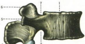
Guides for fixing the keel (aluminum corner 40x20x2 mm) with slots for frames (slots are made for a specific model) - photo 1-2;
- curly guides, along which, during the installation of the frames, the carriage (10 mm plywood, figured strips) moves along the keel with a 4mm duralumin plate, adjustable in height, located at right angles to the keel (for installing and fixing the frames) - photo 3-5;
- side posts (board 20mm) with the ability to move along the keel and perpendicular to it (for fixing the hull) - photo 6;
- parallel clamps (oak 20mm).
Photo 1 Photo 2 

Photo 3 Photo 4 

Photo 5 Photo 6 

Photo 7 Photo 8 

Photo 9 
Circular saws
Photo 10 Photo 11


Photo 12 Photo 13


Photo 14 Photo 15


Photo 16 Photo 17


During the operation of the circulars I have (a self-made "mini-factory" for thin strips and veneer, FET PROXXON for thicknesses up to 20 mm and MJ10200J Feida for thicknesses up to 40 mm), I came to the conclusion that it was necessary to build a circular, devoid, if possible, of drawbacks of the listed units (design features that sometimes significantly complicate operation; time and effort spent on ensuring the accuracy of sawing; high noise, etc.).
In particular, the FET circular has an extremely unsuccessful saw blade attachment point - the M4 clamping screw with a head for a hexagonal rod constantly wedges so much that I already had to cut off the head twice, otherwise the disc could not be removed (the same drawback was noted by other modellers). This drawback was largely overcome by the FET by replacing the pressure washer and the mentioned screw with a different one, with a 10 spanner head (photo 19-20).
Photo 19 Photo 20


The initial ideas for the construction of the new circular were:
The main cutting range is wood with a thickness of 0.5 to 20 mm;
- cutting accuracy 0.1mm;
- sawing at various angles;
- table height adjustment;
- reliable attachment point for the saw blade and ease of replacement;
- power reserve, excluding (reducing) engine overheating during long-term operation;
- noise reduction.
As a result of viewing and analyzing a large number of descriptions of industrial and homemade circulars, I came to the creation of the structure shown in photos 21-24.
Photo 21 Photo 22


Photo 23 Photo 24


The spindle assembly, which implements the direct drive, was made according to the drawings developed by the modeler Boris B. Compared with the original drawings, the diameter of the coupling halves is reduced by 6 mm so that they do not protrude beyond the flange dimensions. A description of Boris B's circular can be found here: http://www.shipmodeling.ru/phpbb/viewtopic.php?f=10&t=1421&start=465. Direct drive, in my opinion, has a number of indisputable advantages over belt transmission - it reduces power loss, simplifies assembly and adjustment of the cutting unit, and also makes much less noise than other types used in circulars. drives.
The circular used a 370 watt motor (characteristics are shown in photo 25) from a water pump. The drive details are shown in photo 26. Photo 27 shows the mold in which a cross-shaped gasket for the half-couplings was made of silicone. Photo 28 shows the details of fastening to the table and moving the stop (guide). A screw pair with a 12 mm screw with a multi-thread thread was used, one revolution of which provides a smooth movement of the carriage with an emphasis of 12 mm along the table. The material of the spindle assembly is st 45, the details of fastening the stop to the table are D16T duralumin 15 mm thick, the stop (guide) with a section of 16x20 mm from D16T, the carriage lock - D16T, the screw in the M6 fixator from Art 45, the axis of the lock is silver steel with a diameter 6 mm. The engine stands on rubber pads 10 mm thick, rubber pads are also installed on the base legs, their attachment to the base and under the engine mounting bolts. Photo 29-30 shows the attachment of the spindle assembly to the motor and base. Flange mounting stand (central) 200x105x8 mm made of D16T, M8 flange fixing screws, intermediate stand - 24 mm plywood (glued 2x12 mm), side racks - 12 mm plywood, mounting angles - steel 2 mm, M5 screws.
Photo 25 Photo 26


Photo 27 Photo 28 

Photo 29 Photo 30


Photos 31 - 32 show a cutting unit to which saw blades of various sizes and designs can be easily attached depending on the needs (for example, with a stop fixed on the surface for the manufacture of gratings, etc.). Saw blades with a diameter of 63, 80 and 115 mm are also shown here (the main sizes suggested for use). In general, the design is designed for the use of discs with a maximum diameter of 160 mm. Photo 33 shows the design of the saw table: the actual table 380x330x5mm from D16T, the corner from D16T on the back - the guide for moving and fixing the back of the stop, the corner from D16T on the side - to move the protractor (oblique cutting). The table rotates on a steel axle with a diameter of 6 mm, the ends of which are fixed on vertical steel posts (angles) with a thickness of 3 mm.
Making various crafts, furniture, self-repairing a car with your own hands, are popular not only because of the innate ability of our people to create. This is also a good saving for the family budget.
However, this hobby requires special equipment. Every home has basic hand tools, including electric ones. Drill, screwdriver, grinder, hand circular saw, jigsaw.
These devices facilitate the work of the home craftsman, but with their help it is impossible to carry out the work professionally. The home workshop should be equipped with compact machines.
Review of homemade machines for a home workshop - video
This technique is offered in abundance by specialty stores.
Equipping the workplace with such an arsenal, you can make anything you want. But the high cost of the tool negates the savings in the production of crafts.
One thing remains - to make machines with your own hands. Homemade equipment can work just as well as factory equipment. In addition, constructive know-how can be brought in to empower.
Homemade woodworking machines for a home workshop
Wood lathe
It can be made from existing tools. A sturdy table is enough, or just a massive board mounted on legs. This will be the bed.
The clamping spindle is not required for wooden workpieces. As well as a separate drive motor. There is a simple complex solution - an electric drill.
If there is a speed regulator, it's generally great. A feather drill for wood is fixed in the chuck. It needs to be finalized: sharpen the working edge in the form of a trident.
The next required element is the tailstock. In metal lathes, it is necessary to support long blanks. When processing wood on a machine without a clamping spindle, the tailstock is the fixing element. It presses the blank against the trident and supports it on the axis of rotation.
Typical tailstock design illustrated. 
The cutter in such a machine is not fixed in the support. Wooden blanks are processed with a manual chisel, which is supported by a hand-hand.
Homemade wood milling machines
The complexity of the tool depends on the type of work performed. For basic face-cutting, simply place a hand router under a flat worktop.
The power tool is mounted upside down, the working attachment protrudes above the surface. Such homemade looms are widespread among DIYers.
Important! Industrial tools are designed and built with safety in mind. A rotating router can cause serious injury, so the attachment must be secure and the working area protected from the operator's extremities.
If the arm for the hand router is equipped with a height adjustment device, you will receive semi-professional equipment.
Each master strives to equip his sphere as much as possible, to saturate the working space with machine tools and fixtures. Home-made machines and accessories for a home workshop are of great benefit for running a private household.
Homemade household items and equipment include:
- joinery;
- crafting table;
- stool;
- shelves;
- racks.
Crafting table
Workbench dimensions
The height of the countertop surface should be such that the worker can stand up to operate tools and equipment. The owner of the workshop determines the height of the workbench himself - according to his height. The height of the worktable ranges from 75 cm to 80 cm.
The size of the countertop is determined by the area of the utility room. The table should not obstruct free passage around it.
Workbench material
Wood
A wooden table is often used. The workbench is made of timber and boards. The legs of the table are fastened with diagonal crossbars for reliability.
The table top is made in the form of a shield from knocked down boards with pieces of timber. The shield is supported on the table legs and fastened with nails or screws. Connection details are made of steel angle.
The options for assembling a wooden workbench are different, but in one thing they are the same - the design of the table must be stable and withstand static and dynamic loads.
If the surface of the workbench will be exposed to accidental effects of cutting and sharp tools, then the tabletop is upholstered with tin or a metal sheet is placed on top.
Metal
The most reliable design of the working table is a workbench welded from a metal profile. Manufacturing a welded product requires a welding machine and experience with it.
The base frame and table legs are welded from a steel corner and a strip. For auxiliary parts, reinforcement segments are used.
The table top is made of a metal sheet, 8 - 12 mm thick. A thick sheet will significantly increase the weight of the workbench, making it difficult to move.
Stool

It is quite simple to make a stool with your own hands:
- 4 supports are made of 40 x 40 mm timber, 50 cm long.
- Legs in the middle of the length are fastened with crossbars.
- In the supports, grooves are made with a chisel.
- At the ends of the transverse strips, projections are cut out with a chisel to fit the grooves.
- The protrusions are lubricated with wood glue and inserted into the grooves.
- While the glue dries, the supports are tightened with a belt.
- The seat is cut with a circular saw from a wide board with a thickness of 30 mm.
- A seat measuring 300 x 300 mm is nailed or screwed to the legs of the stool.
Shelves
Shelves are made of board, chipboard or MDF. They are open or with side walls. For fasteners, hinged furniture hinges are used.
Holes are drilled in the wall into which dowels are driven. The screws are not completely screwed into the dowels so that the shelf hinges can be put on them.
The hinges are screwed to the back of the shelf. The shelves are hung on the wall by putting hinges on the screw heads.

Racks
Racks are a whole range of shelves of different sizes. It is good to make them from chipboard. The lattice structure is supported on a pedestal or simply placed on the floor. For the stability of the rack, the corners are screwed to the sides of the furniture. The free shelves of the corners with holes are nailed to the wall with dowels.
Vertical tool holders
Every craftsman strives to organize his workplace so that the tools are at arm's length. This is facilitated by the vertical holders.

Wrench holder
- A wooden plank is attached to the wall above the workbench. The rail is screwed into the dowels installed in advance.
- Small nails are driven into the bar at intervals equal to the width of the wrench handles.
- The keys are hung on a rail.
- The nail heads hold the keys horizontally and vertically.
Screwdriver holder
- In a 40 x 40 mm piece of timber, holes are drilled corresponding to the diameters of the screwdrivers, at a distance of 30 - 40 mm from each other.
- A piece of timber is nailed to the wall with dowels so that the holes are vertical.
- Screwdrivers are inserted into the resulting sockets. Now you can quickly get the right tool without leaving your workplace.
Chisel belt
- The plank is attached to the wall with dowels.
- The belt or belt is nailed to the bar with nails so that a kind of through pockets are obtained.
- Chisels are lowered into the pockets, through which only steel blades pass. The handles are held in place by a strap.
The device can hold hammers, pliers, pliers and other tools.
Homemade soldering iron stand
Working with a soldering iron, a situation arises when you need to put the tool aside. Putting a soldering iron with a hot tip on a tabletop or on any object is always risky. A homemade stand will solve this problem.
An example of making a stand for a soldering iron
- The holder is made of wire in the form of a spiral. To do this, unbend a wire hanger.
- The wire is wound on a cylindrical object with a diameter of 1.5 - 2 cm. The handle of a chisel or other tool will do.
- On one side, the springs leave a free end of the wire.
- The end is bent with round-nose pliers into a loop.
- For the base of the stand, take a board 200 x 100 x 20 mm.
- A ø 4 mm through hole is drilled into the base.
- On the back of the board, the hole is drilled with a large drill - under the screw head.
- The screw is threaded from bottom to top.
- A spring loop is put on the screw and the nut is tightened.
- Circles are cut into the board with a crown to match the size of a cup for candles or similar products.
- A chisel is used to sample wood in 3 grooves.
- Cups are inserted into the openings, which are filled with solder, tin and a napkin for cleaning the tip.
- The soldering iron is inserted into the spring.
- A small hole is made in the board for attaching a flexible steel cord from the lamp.
- At the end of the cord, a clamp is fixed, with which various parts for soldering are fixed.
The design may have a different look - it all depends on the imagination and ingenuity of the author.
The easiest mousetrap in the world

This name can be attributed to many homemade mousetraps invented by craftsmen. They are united by one thing - this is the humane treatment of animals that have fallen into a trap. The device does not kill the animal, but isolates it. Here are some examples of how to make a simple mousetrap:
Plastic funnel
Cut a plastic 3 liter balloon in half. The cut neck is turned over and inserted into the bottom of the bottle. Bait is poured onto the bottom (seeds, grain, etc.).
The trap is placed close to an object on which the mouse could climb. The rodent, having fallen into the funnel, can no longer get out of the bottle.
Console
The structure is a tipping platform. It is made from a piece of cardboard or plastic. The bar is placed on a plane so that half of it hangs in the air.
The bait is placed on the edge of the console so that the bar is on the verge of balance. The animal, having reached the bait, knocks over the bar and falls with it into the bucket that has been substituted.
Suspension
An empty plastic bottle with bait at the bottom is placed on the edge of the table. A cord is attached to the neck by piercing the plastic with a crochet from a paper clip. The other end of the cord is tied to some kind of support.
The mouse, attracted by the smell of food, enters the container. The bottle overturns under the weight of the rodent and hangs on the cord.
Metal loop mini vise

When performing small operations, it is often necessary to clamp small parts. To do this, use a mini vise made of a one-piece door hinge.
In both flaps, the hinges are drilled matching holes.
A bolt of a suitable diameter is threaded through them. On the other hand, a wing nut is screwed onto the bolt thread. Parts are inserted into the opening between the flaps and clamped by tightening the nut. The device can be used as a clamp.
Portable beer crate
A box for drinks in a glass container is a convenient device for carrying several bottles at once in the country or at a picnic. To make such a box with your own hands, you will need the following tools and materials:
Tools
- jigsaw;
- saw on wood;
- grinder;
- drill screwdriver;
- drill;
- a hammer;
- chisel;
- feather drill.
Materials (edit)
- edged board - 1050 x 170 x 15 mm;
- strips from the fruit box - 5 pcs.;
- handle ø 36 mm and length 350 mm;
- stain;
- screws;
- nails.
Step-by-step instructions for assembling the box
- The edged board is sawn into three identical parts (bottom and two sidewalls), 350 mm long.
- Two boards are cut with a jigsaw so that from their middle the sidewalls taper and end with an oval top.
- In the tops of the sidewalls, holes ø 36 mm are drilled with a feather drill.
- All wooden parts are cleaned with a sander with an emery wheel. The handle is sanded by hand with emery.
- 4 holes are drilled with a thin drill along the edges of the bottom. From the bottom, the holes are countersunk.
- The sides are installed on the sides of the bottom. Screws are screwed in from the bottom of the bottom. The screw heads "hide" in the hole slots.
- Two strips are nailed to the sides with studs on each side of the box. They will become a vertical bottle guard.
- In three slats, cuts are made so that by folding them, you get a crate with square openings for glass containers.
- The crate is laid on the bottom between the sidewalls.
- Carnations are nailed in those places where the ends of the crate rest against the sidewalls and guardrails.
- A shank of ø 36 mm is threaded into the holes of the tops of the sidewalls.
- Driving in nails at an angle, fasten the sidewalls with the handle.
- The entire surface of the box is treated with stain.
The box is ready for use. The portable container is free for 6 bottles of beer or other drink. The crate and railings of the box will prevent bottles from breaking or falling out during transport.
Hammer modernization
A common occurrence is a wooden handle falling out of the hammer socket. One of the ways to create a secure attachment of the handle is to make a cut in the upper end of the handle. The holder is inserted into the socket of the hammer. The kerf is filled with Moment glue. A wooden wedge is driven into the groove.
In order not to look for nails during work, and even more so not to hold them with your teeth, a round magnet is glued into the hammer handle from below. Magnetic nails will always be at hand for the worker.
It is dangerous to accidentally fall out of the hand at a height. To prevent this from happening, a hole is drilled in the handle through which the cord is threaded. The employee's belt is threaded into the loop.

Homemade tools and machines
Pipe bender
The metal pipe bending device is a metal rod welded to the bed. The rod is made from a piece of reinforcement. The pipe is put on the pin, and on the other side, a long piece of reinforcement is inserted into the pipe. By pressing the lever, the pipe is bent at the desired angle. The device is suitable for small sections of round pipes.

Bending device for profiled pipes
Greenhouse owners know how important it is to have a device for bending lengths from a profile pipe. The curved profile is used as an arched structure for the formation of polyethylene coverings for greenhouses.
The pipe bender allows you to save a lot of money on the construction of a greenhouse. The design consists of 3 rollers - two are guides, and the third roller performs the leading function.
The profile tube is inserted into the opening between the two wheels and the roller. The roller has a stop and a swivel device in the form of a lever or an electric motor drive.
Making a pipe bender with your own hands
- Two axles are welded to a metal frame from pieces of smooth reinforcement, onto which old automobile hubs are put on.
- The protruding chamfers are removed from the hubs so that the side surfaces of the rollers are smooth.
- A channel is placed in the opening between the hubs with the shelves up.
- The same profile is inserted into the channel, of a smaller width, with the shelves down.
- An axle is welded to the inner profile from above, on which the third hub is put on.
- A vertical sheet steel shelf is welded to the bed.
- A hole is cut in the vertical bar and a bearing is pressed into it.
- The nut is fixed on the middle channel by welding.
- At one end, the screw shaft is screwed into the nut.
- The screw shank is threaded through the bearing in the vertical bar.
- On the back of the strap, a rotary handle is welded to the shank.
- A pivot arm is welded to the axis of the drive hub.
The machine is now ready for use. A profile pipe is inserted between the rollers and clamped with a screw. The pivoting lever sets the rollers in motion, which pull the pipe, bending it. The bending radius is set with the rotary screw handle.
A pipe bender from car hubs is one of the device options. There are many designs of bending devices. In some models, the drive roller is coaxially connected to the motor shaft.
Impact screwdriver from starter
There are situations when it is impossible to unscrew a rusted bolt or screw with a regular tool. An impact screwdriver does an excellent job with this. The tool is made by hand from parts of a car starter:
- The shaft and bushing are removed from the starter housing.
- Part of the shaft is cut off, leaving the spline rod.
- A piece of pipe of a suitable size is put on the sleeve.
- A bolt of equal diameter is welded to the end of the pipe.
- The end of the shaft is turned in the form of a tetrahedron, on which heads of the desired size are put on. For screws, a bit is inserted into the head.
When hitting the head of the bolt with a hammer, the shaft slides with beveled splines inside the sleeve, making a rotational movement. The stronger the blow, the more effort the shaft turns.

Homemade circular saw
A do-it-yourself cut-off machine from a grinder is not inferior to some factory-made samples. The grinder is a fairly powerful circular saw.
The machine on the basis of the grinder performs precise cuts of lumber and metal profiles. For its manufacture, you will need the power tool itself, a welding machine and a metal profile.
Step-by-step instructions for assembling the machine
- Two metal strips are welded to the pipe section, in which the mounting holes are drilled.
- Accordingly, two holes are also made in the grinder's casing.
- The strips are bolted to the casing.
- The machine bed is made of a metal sheet with support corners welded from below.
- By welding, a vertical segment of the angle is attached to the bed, in which a hole is drilled.
- A piece of angle is welded to the lower end of the lever and drilled through with the pipe.
- The bolt is threaded through the holes and the hinge joint of the vertical rack with the lever is tightened with a nut. Additionally, a locknut is installed.
- In the vertical position, the grinder lever takes a stable position.
- At the point of contact of the saw blade with the bed, a cut is made so that the blade can completely cut the workpiece.
- The handle of the power tool is moved to the end of the lever.
- As additional devices, a cross and corner stop are installed on the bed.

If necessary, remove the power tool from the machine and use the circular saw in manual mode.
Homemade bow saw
Bow saw is a handy tool for sawing tree trunks and sawn timber. The design of the saw is simple, making a hand tool with your own hands is not difficult. To do this, you need to prepare tools and materials:
Tools
- drill;
- saw-hacksaw;
- chisel;
- a hammer;
Materials (edit)
- cord;
- wooden lath 20 x 40 mm;
- cotter pins - 2 pcs.;
- handle ø 10 mm;
- saw blade;
- stain;
- varnish on wood.
Step-by-step instructions for making a bow saw
- The strip is sawn into three parts (two vertical side strips and a middle horizontal strip).
- In the side handles, grooves are made with a chisel.
- At the ends of the centerpiece, projections are cut out with a chisel for the grooves.
- The mullion is connected to the side handles.
- Through holes are drilled at the joints. Wooden cotter pins are driven into them.
- The cotter pins form articulated joints. This is necessary for the mobility of the lower ends of the side rails when tensioning the web.
- At the lower ends of the sidewalls, cuts are made - parallel to the middle.
- Short bolts are inserted into the holes of the saw blade and tightened with nuts.
- The blade is led into the cuts so that the bolts are outside the structure.
- Circular grooves are cut at the upper ends of the handles.
- At the ends of the double cord, loops are made, which are put on the grooves.
- A handle is inserted between the strings of the cord, the long end of which rests against the middle.
- The string of the saw is twisted with a handle, achieving the desired degree of tension on the saw blade.
- The wood is covered with wood stain and two layers of varnish.
- After the varnish has dried, the saw is ready for use.
Conclusion
Home-made devices, tools and machine tools not only bring significant benefits to the backyard, garage and household, but also significantly save the family budget. When making and using homemade products, one must not forget about safety rules.
Currently, you can buy ready-made machines to equip your own workshop, but all this will be quite expensive. Homemade machines help the master in his practical work, while not burdening his budget. Why buy something that you can do with your own hands, and even in relation to specific conditions.
Each owner chooses the equipment of his own workshop. It depends on the characteristics of the hobby, i.e. type of work and area of the room. The minimum area of a home workshop in which it makes sense to place equipment is 3-4 m².
It can be located in a small room or on the balcony of an apartment, in a separate building on its own plot or in a garage. Ideally, this is a secluded area where you can make noise without disturbing other people.
Home workshop according to its purpose can be universal, i.e. to carry out any work that unexpectedly arises in everyday life, or have a specific direction associated with the hobby of the master. Most often, workshops are equipped for working with wood, i.e. for carpentry work... Quite often there is a need for metal processing ( locksmith work) and car repair.
In general, the arrangement of a home workshop includes the following elements:
- structures for placing tools and materials (racks, shelves, cabinets);
- equipment for work (workbenches, work tables);
- material processing machines;
- devices for mechanization of work, ease of labor, preparation of tools, etc.
Place the equipment so that it has free approach, was respected safety and fire regulations, provided the minimum comfort.

Shelves for tools and materials
Setting up a home workshop begins with the installation of practical shelves for a tool with your own hands. They can be made of metal or wood, and also have a combined structure - a metal frame with shelves made of wood, plywood, chipboard, plastic, etc.
There are such basic constructions:
- Shelves in the form of a frame and shelves located at different heights.
- Wall mounted shelves. They can be mounted on brackets or fixed with dowels directly to the wall surface.
- Hanging shelves with ceiling mounting.
 Practical shelves are designed like this. The base is made up of a shield cut from plywood with a thickness of 8-12 mm.
Mounts of 3 types are mounted on it:
- rail with slots for placing a tool with a handle in a vertical position (hammer, screwdrivers, chisels, etc.);
- shelves with a rim for installing boxes with small tools (drills, taps, dies, etc.);
- hooks for hanging a small tool (knife, scissors, measuring tool, etc.).
Such a shelf-shield is fixed to the wall with dowels.
Joiner's workbench
The joiner's workbench is a sturdy table with a work surface on which to attach holdfast(2 pieces), retainers to secure the workpiece when planing with a plane, there are places for installation milling cutter and other hand-held machines.
Important. The dimensions of the workbench are selected for practical reasons.
The height should provide ease of work, taking into account the actual growth of the master. The length should be not less than 1 m (usually 1.7-2 m), and width - 70-80 cm.
Instructions for making a joinery workbench:
- The working surface is made in the form of a board with tightly fitted boards with a thickness of at least 55 mm. Beech, oak, hornbeam are best suited. Beforehand, they should be impregnated with linseed oil. Strengthening is achieved by a 4-5 cm bar, which is attached around the entire perimeter of the shield.
- The vertical table supports can be made from pine or linden. Usually a beam of 12x12 or 15x15 cm in size is used with a length of about 120-135 cm. The supporting elements are connected by horizontal jumpers from a wide board, fixed at a height of 20-30 cm from the floor.
- Storage of tools and accessories is carried out on shelves, which are located under the lid. It is better to make them in the form of a cabinet with a door. Shelf shields can be placed on the wall above the workbench.
- A pair of homemade or factory carpentry vices is attached to the work surface.
reference... The workbench can be mobile (mobile), folding (collapsible) or stationary. In the latter case, it is recommended to deepen the supports into the ground by 15-20 cm.
Vise
 A homemade vise will require a long screw rod with a diameter of at least 20 mm with a length of the threaded part of at least 14-16 cm, metal studs and wooden bars.
Manufacturing is carried out in the following order:
- A wooden block (can be made of pine) is cut out about 20x30 cm in size and at least 5 cm thick, in which a hole for a screw is drilled in the center, and at the bottom there are 2 holes for guide pins. This first vise jaw is permanently attached to the work surface.
- The second sponge is cut from a similar board and measures 20x18 cm. This will be a movable element.
- A screw pin is passed through the jaws. To eliminate the displacement of the elements, studs with a diameter of about 8-10 mm are fixed. A handle is installed on the screw rod.
How to make a metal workbench with your own hands?
A metal workbench is required for locksmith work. Its standard size: length 1.8-2.1 m, width - 0.7-0.8 m, height - 0.9-1.2 m. Manufacturing includes the following stages:
- Assembling the frame of the workbench with imparting longitudinal rigidity.
- Assembling and fixing 2 pedestals in the form of a frame, sheathed with a metal sheet.
- Installation of a working surface - a wooden board, sheathed on top with a metal sheet.
- Installation of a tool rack, which is fixed to the back of the workbench and additionally strengthens it.

- rack beams - a profile pipe with a wall of at least 2 mm, measuring 4x6 cm. You need - 4 pcs.;
- 5x4 cm beams for horizontal tie-down of uprights, providing longitudinal rigidity. Quantity - 3 pcs.;
- profiled pipe (9 pcs) for the manufacture of a frame of pedestals about 4x3 cm in size with a wall thickness of at least 1 mm;
- corner 5x5 cm for vertical racks of the rack with a height of 1.5-2 m. For horizontal alignment, you can use a corner of 4x4 cm;
- board for countertops with a thickness of at least 5 cm;
- metal sheet for the working surface with a thickness of at least 6-8 mm.
Features of creating a wood lathe
A homemade lathe for working with wooden blanks includes the following elements:
- Stanina... It must be strong enough. It is better to make it from a metal profile (pipe, corner), but it is also possible from a wooden bar. It is important to securely fix the frame to the workshop floor and make the structure heavier at the bottom.
- Headstock or clamping spindle... As this element of the machine, you can use a head from a drill of increased power.
- Tailstock... In order to provide longitudinal feed of the workpiece, it is better to use a standard factory spindle with 3-4 jaws.
- Support or cutter rest... It must provide reliable fastening and the ability to move towards the workpiece, which is provided by a screw rod.
- Tool table... A working surface should be formed on the bed on which the cutters and other tools can be laid out.
- Drive unit... To create a torque, an electric motor with a rotation speed of 1500 rpm and a power of 250-400 W is used. You can use a motor from a washing machine. A belt drive is used as a transmission, for which pulleys of the required size are installed on the shafts.

Incisors
Even in a homemade lathe, it is better to use factory cutters that will provide increased quality. However, if you wish, you can do with this issue on your own. Homemade incisors wood can be made from the following materials:
- Steel reinforcement... The best option is a square section with a size close to the size of the factory tool.
- Files... A worn-out tool is selected, but without significant defects.
- Car spring rectangular (square) section.
Prepared cutter blanks sharpened... For roughing work, a semicircular cutting edge is used, and for finishing work, a cutter with a straight blade is required. In addition, profile and pass-through cutters with specific sharpening may be required. Further, the cutting part requires hardening... To do this, it is heated and then dipped in engine oil.
Instructions for creating a stationary circular saw
The most important element of a stationary circular saw - reliable table with work surface... A metal sheet reinforced with stiffeners from a steel corner is most suitable for it. The following parts are located on the worktop: cutting disc, guides, thrust and adjusting elements.
 The drive is provided electric motor power of about 0.8 kW with a minimum speed of 1700 rpm. Transmission - belt drive.
You can make a circular saw from the grinder in the following order:
- Installation of the frame and manufacturing of the working surface. Cutting the space for the disc installation.
- Fastening parallel stops made of wooden beams.
- Installation of a scale for adjusting the cutting process.
- Installation of clamps to fix the guides and the workpiece.
- Securing the grinder from the bottom of the table top with the disc directed into the slot.
Assembling a homemade drilling machine
The procedure for assembling a homemade drilling machine shown in the video below... It is based on an electric drill, which is fixed on the bed with the possibility of vertical movement.
The main elements of the machine:
- Electric drill.
- Metal base with workpiece clamps (clamps).
- Drill stand. It can be made of chipboard 2-2.5 cm thick. A good option is a base from an old photo enlarger.
- Cutting tool feed mechanism. On the rack, guide rails are installed to ensure a strictly vertical movement of the drill. The easiest way to feed the tool is lever for manual pressing and spring... To control the depth, adjustable stops are mounted.
CNC milling machines for wood and metal
When milling wood software allows you to significantly expand the capabilities of the machine and the quality of processing. For its formation, such elements are installed as LPT port and CNC unit... For the manufacture of a copy unit, you can use the carriages of an old dot matrix printer.

The assembly of the wood router is carried out in the following order:
- The table top is made of chipboard or plywood with a minimum thickness of 15 mm.
- A cutout is made for the cutter and its installation.
- The drive, transmission and machine spindle are attached.
- Stops and stops are installed.
 Assembling a router for metal requires a stronger foundation for the machine:
- Installation of the column and bed in the shape of the letter "P". Elements are made of steel channel. In the U-shaped design, the jumper is formed by the base of the tool itself.
- The guide elements are made of steel angle and are bolted to the column.
- The guide arms are made of rectangular tubes. A screw pin is inserted into them. The movement of the console is provided by a car jack to a height of 12-15 cm.
- The worktop is made of chipboard or plywood.
- A vice, guides from a metal corner, pin clamps are fixed on the tabletop.
- The rotating part is installed so that the shaft is vertical.
Thicknesser
Homemade wood thicknessing machine includes the following elements:
- Stanina... It is made of 2 frames welded from a corner of 40x40 or 50x50 mm. The frames are connected with studs.
- Broach... Squeeze rollers made of rubber from a washing machine work well. They are put on bearings and rotated by hand using a handle.
- Working surface, table top... A wide board impregnated with linseed oil is used, which is bolted to the bed.
- Drive unit... We need a three-phase electric motor with a power of 5-6 kW with a rotation speed of at least 3000 rpm.
- Shroud... To protect the rotating parts, a steel sheet casing with a thickness of 4-5 mm is installed, fixed on a frame made of a steel corner 20x20 mm.
note
As a working body, you can use electric plane.

It is fixed with clamps on the working surface with the formation of the required gap. This gap should be adjusted with shims and adjusted according to the thickness of the workpiece.
Creating a Wood Grinder
Homemade grinding machine has drum structure, i.e. rotating cylinder with put on it emery (grinding) sandpaper... It can be made of the following varieties:
- surface grinding type providing grinding in one plane only;
- planetary a type capable of processing a part in different directions, creating a flat plane on it;
- circular grinding type for processing cylindrical workpieces.
When fixing the abrasive cloth, the following recommendations should be taken into account:
- The width of the tape is chosen about 20-25 cm.
- The strips are joined end-to-end, without a gap.
- To strengthen the butt joint, a dense tape is laid under it.
- Only high quality glue should be used.
- The shaft for the emery strip has a side at the edges that protrudes 2.5-4 mm.
- It is recommended to use thin rubber (e.g. bicycle tube) as a backing for the abrasive element.

Rules for the operation of a planer for wood
A homemade planer will help when repairing furniture and an apartment. When operating it, the following rules should be observed:
- The jointer is adjusted so that such maximum errors are ensured - vertically (perpendicular) - no more than 0.11 mm for each 1 cm; in the plane - no more than 0.16 mm for each 1 m.
- When processing workpieces less than 3.5x35 cm in size, pushers should be used to hold them.
- The wear of the cutting element is indicated by the scorch marks and mossiness on the surface of the part.
- An uneven surface after machining indicates an inaccurate positioning of the cutting edges.

Homemade garage accessories
In a home workshop equipped in a garage, you can provide your own car repairs. In particular, the following homemade devices and machines are of interest.
Hydraulic jack press
 He will help when removing and crimping silent blocks car. With its help, a load of several hundred kg is provided.
The structure consists of a frame and a hydraulic jack. The frame is welded from a high strength rectangular tube.
After lifting the car, it is she who becomes a stationary, reliable support for the car.
This allows you to safely press out the jammed part. with the use of internal clips from the bearing.
Ball joint remover
It can be made in different ways:
- Lever type... These are 2 levers connected in the center. On one side, a tightening bolt is installed on them. When acting on the support, it unscrews, bringing the ends of the levers closer together. In this case, one end is wound between the support and the eyelet, the other - under the finger.
- Wedge option... A wedge-shaped blank is cut from a metal plate. From the side of the upper corner, a strictly vertical cut is made at 70% of the height. This wedge is installed between the ball joint and the lug. Then it clogs in until the finger comes out of the socket.
Many home craftsmen are thinking about how to make a metal lathe on their own. This desire is explained by the fact that with the help of such a device, which will be quite inexpensive, it is possible to efficiently perform a large list of turning operations, giving metal blanks the required dimensions and shape. It would seem that it is much easier to purchase the simplest desktop machine and use it in your workshop, but given the considerable cost of such equipment, it makes sense to spend time making it yourself.
Homemade lathe is quite real
Using a lathe
The lathe, which was one of the first to appear in the line of equipment for processing parts from various materials, including metal, allows the manufacture of products of various shapes and sizes. With the help of such a unit, it is possible to turn the outer and inner surfaces of the workpiece, drill holes and bore them to the required size, cut external or internal threads, and perform knurling in order to give the surface of the product the desired relief.
A serial lathe for metal is a dimensional device that is not so easy to operate, and its cost is very difficult to call affordable. It is not easy to use such a unit as a desktop equipment, so it makes sense to do it yourself. Using such a mini-machine, you can quickly turn workpieces made not only of metal, but also of plastic and wood.
On such equipment, parts with a circular cross-section are processed: axles, tool handles, wheels, structural elements of furniture and products for any other purpose. In such devices, the workpiece is located in a horizontal plane, while rotation is given to it, and the excess material is removed by a cutter securely fixed in the machine support.

Despite the simplicity of its design, such a unit requires a clear coordination of the movements of all working bodies in order for the processing to be carried out with the utmost precision and the best workmanship.
An example of a homemade lathe with drawings
Let's take a closer look at one of the working options for a self-assembled lathe, the rather high quality of which rightfully deserves the closest attention. The author of this homemade product did not even skimp on the drawings, according to which this device was successfully manufactured.
Of course, not everyone needs such a thorough approach to business, often simpler structures are built for household needs, but as a donor for good ideas, this machine fits perfectly.

Machine appearance Main assemblies Support, tool holder and chuck
Side view Tailstock Bottom view of the tailstock
Idler shafts Caliper design Motor driven
Drawing No. 1 Drawing No. 2 Drawing No. 3
Structural units
Any, including home-made, lathe consists of the following structural elements: a supporting frame - a bed, two centers - a leading and a driven, two heads - front and rear, a spindle, a support, a drive unit - an electric motor.

All elements of the device are placed on the bed; it is the main bearing element of the lathe. The headstock is a fixed structural element on which the rotating spindle of the unit is located. In the front part of the frame there is a transmission mechanism of the machine, with the help of which its rotating elements are connected with an electric motor.
It is thanks to this transmission mechanism that the workpiece is rotated. The tailstock, in contrast to the front, can move parallel to the direction of machining, with its help the free end of the workpiece is fixed.

A home-made metal lathe can be equipped with any electric motor, even not too high power, but such a motor can overheat when processing large-sized workpieces, which will lead to its stop and, possibly, failure.
Usually, electric motors are installed on a homemade lathe, the power of which is in the range of 800-1500 watts.
Even if such an electric motor has a small number of revolutions, the problem is solved by choosing an appropriate gear mechanism. To transmit torque from such electric motors, belt drives are usually used; friction or chain mechanisms are very rarely used.
Mini-lathes, which are equipped with home workshops, may not even have such a transmission mechanism in their design: the rotating chuck of the unit is fixed directly to the motor shaft.

There is one important rule: both centers of the machine, the leading and the driven, must be located strictly on the same axis, which will avoid vibration of the workpiece during its processing. In addition, it is necessary to ensure reliable fixation of the part, which is especially important for models of the frontal type: with one leading center. The issue of such fixation is solved using a cam chuck or faceplate.
In fact, a do-it-yourself lathe can be made with a wooden frame, but, as a rule, metal profiles are used for these purposes. The high rigidity of the lathe frame is required so that the accuracy of the location of the driving and driven center is not influenced by mechanical loads, and its tailstock and support with the tool move freely along the axis of the unit.

When assembling a lathe for metal, it is important to ensure reliable fixation of all its elements, be sure to take into account the loads to which they will be subjected during operation. What dimensions your mini-machine will have, and what structural elements it will consist of, will be influenced by the purpose of the equipment, as well as the size and shape of the workpieces that are planned to be processed on it. The power of the electric motor, which you will need to use as a drive, will also depend on these parameters, as well as on the magnitude of the planned load on the unit.

For equipping lathes for metal, it is not recommended to choose collector motors, which differ in one characteristic feature. The number of revolutions of the shaft of such electric motors, as well as the centrifugal force developed by the workpiece, increase sharply with decreasing load, which can lead to the fact that the part will simply fly out of the chuck and can seriously injure the operator.
Such electric motors can be used if you plan to process small and lightweight parts on your mini-machine. But even in this case, it is necessary to equip a gearbox that will prevent the uncontrolled increase in centrifugal force.

It has already been proven by practice and design calculations that for turning units, on which metal workpieces up to 70 cm long and up to 10 cm in diameter will be processed, it is best to use asynchronous electric motors with a power of 800 watts or more. Engines of this type are characterized by the stability of the rotational speed in the presence of a load, and when it decreases, it does not increase uncontrollably in them.
If you are going to make a mini-machine on your own to perform turning work on metal, then you should definitely take into account the fact that not only transverse, but also longitudinal loads will act on its chuck. Such loads, if not provided with a belt drive, can cause destruction of the motor bearings, which are not designed for them.
If it is not possible to use a belt drive, and the driving center of the device is directly connected to the motor shaft, then a number of measures can be provided to protect its bearings from destruction. A similar measure can be a stop that limits the longitudinal movement of the motor shaft, which can be a ball installed between the motor housing and the rear end of its shaft.
In the tailstock of the lathe, its driven center is located, which can be stationary or freely rotate. The simplest design has a fixed center: it is easy to make it on the basis of an ordinary bolt, sharpening and grinding under a taper that part of it that will be in contact with the workpiece. By screwing or unscrewing such a bolt moving along the threaded hole in the tailstock, it will be possible to adjust the distance between the centers of the equipment, thereby ensuring reliable fixation of the workpiece. Such fixation is also provided by moving the tailstock itself.
In order for the workpiece to rotate freely in such a stationary center, the pointed part of the bolt that comes into contact with it will need to be lubricated with machine oil before starting work.

Today it is not difficult to find drawings and photos of lathes, according to which you can independently make such equipment. Moreover, it is easy to find various videos demonstrating the process of their manufacture. It can be a mini-CNC machine or a very simple device, which, nevertheless, will give you the ability to quickly and with minimal effort to produce metal products of various configurations.
The racks of the simplest metal lathe can be made of wood. They will need to be securely fastened to the machine frame using bolted connections. The frame itself, if possible, is better made of metal corners or a channel, which will provide it with high reliability, but if they are not at hand, you can also pick up thick wooden blocks.
The video below shows the process of self-manufacturing a caliper for a lathe.