Loss of pressure in the pipes of the refrigerant circuit. Basic rules for the installation of pipelines Regulatory documentation for the design and installation of copper pipelines
Freon chain oil
The oil in the freon system is needed to lubricate the compressor. It constantly leaves the compressor - circulates in the freon circuit along with freon. If, for any reason, the oil does not return to the compressor, the CM will not be lubricated enough. The oil dissolves in liquid freon, but does not dissolve in vapor. Moving along the pipelines:
- after the compressor - superheated freon steam + oil mist;
- after the evaporator - superheated freon vapor + oil film on the walls and oil in drip form;
- after the condenser - liquid freon with oil dissolved in it.
Therefore, there may be a problem with oil retention on steam lines. It can be solved by observing a sufficient speed of steam movement in pipelines, the required pipe slope, and installing oil-lifting loops.
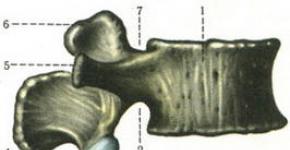
The evaporator is below.
a) Oil scraper loops should be located at intervals of every 6 meters on risers to facilitate oil return to the compressor;
b) Make a collecting pit on the suction line after the expansion valve;
The evaporator is higher.
a) At the outlet of the evaporator, install a water seal above the evaporator to prevent the liquid from draining into the compressor when the machine is parked.
b) Make a collecting pit on the suction line after the evaporator to collect liquid refrigerant that may accumulate during parking. When the compressor is switched on again, the refrigerant will quickly evaporate: it is advisable to make a sump far from the sensitive element of the expansion valve in order to avoid this phenomenon affecting the operation of the expansion valve.
c) On the horizontal sections of the discharge pipeline, a slope of 1% in the direction of the freon movement to facilitate the movement of the oil in the right direction.

The capacitor is below.
No special precautions need to be taken in this situation.
If the condenser is lower than the KIB, then the lifting height should not exceed 5 meters. However, if the CIB and the system as a whole are not of the best quality, then liquid freon may have difficulty in lifting even with smaller differences in altitude.
a) It is advisable to install a shut-off valve at the condenser inlet to prevent liquid freon from flowing into the compressor after the chiller is turned off. This can happen if the condenser is located in an environment with a temperature higher than that of the compressor.
b) On the horizontal sections of the discharge pipeline, a slope of 1% in the direction of the freon movement to facilitate the movement of oil in the right direction

The capacitor is higher.
a) To exclude the flow of liquid freon from the CD to the CM when the refrigeration machine stops, install a valve in front of the CD.
b) Oil lifting loops should be located at intervals of every 6 meters on risers to facilitate oil return to the compressor;
c) On horizontal sections of the discharge line, a 1% slope to facilitate oil flow in the correct direction.

Oil lifting loop operation.
When the oil level reaches the top of the tube, the oil will push further towards the compressor.
Calculation of freon pipelines.
The oil dissolves in liquid freon, so it is possible to maintain a small speed in liquid pipelines - 0.15-0.5 m / s, which will provide a low hydraulic resistance to movement. An increase in resistance results in a loss of cooling capacity.
The oil does not dissolve in the vaporous freon, therefore it is necessary to maintain a high speed in the steam lines in order for the oil to be carried by the steam. When moving, part of the oil covers the walls of the pipeline - this film is also moved by high-speed steam. Compressor discharge speed 10-18m / s. Compressor suction speed 8-15m / s.
On horizontal sections of very long pipelines, it is allowed to reduce the speed to 6m / s.
Example:
Initial data:
Refrigerant R410a.
Required cooling capacity 50kW = 50kJ / s
Evaporating temperature 5 ° С, condensation temperature 40 ° С
Overheating 10 ° С, supercooling 0 ° С
Suction piping solution:
1. The specific refrigerating capacity of the evaporator is q u = Н1-Н4 = 440-270 = 170kJ / kg

Saturated liquid | Saturated steam |
||||||||
Temperature, ° С | Saturation pressure, 10 5 Pa | Density, kg / m³ | Specific enthalpy, kJ / kg | Specific entropy, kJ / (kg * K) | Saturation pressure, 10 5 Pa | Density, kg / m³ | Specific enthalpy, kJ / kg | Specific entropy, kJ / (kg * K) | Specific heat of vaporization, kJ / kg |
2. Mass flow rate of freon
m= 50kW / 170kJ / kg = 0.289kg / s
3. Specific volume of vaporous freon on the suction side
v sun = 1 / 33.67kg / m³ = 0.0297m³ / kg
4.Volume flow rate of vaporous freon on the suction side
Q= v sun * m
Q= 0.0297m³ / kg x 0.289kg / s = 0.00858m³ / s
5.Inner diameter of the pipeline
From the standard copper freon piping, select a pipe with an outer diameter of 41.27mm (1 5/8 "), or 34.92mm (1 3/8").
Outer pipe diameters are often selected according to the tables in the Installation Instructions. When compiling such tables, the steam velocities necessary for transferring oil were taken into account.
Calculation of the volume of freon filling
Simplified calculation of the mass of the refrigerant charge is made using a formula that takes into account the volume of liquid lines. This simple formula does not take into account the steam lines, since the volume occupied by the steam is very small:
Mzapr = P Ha. * (0.4 x V isp + TO g * V res + V w.m.), kg,
P Ha. - density of the saturated liquid (freon) РR410a = 1.15 kg / dm³ (at a temperature of 5 ° С);
V isp - the internal volume of the air cooler (air coolers), dm³;
V res is the internal volume of the receiver of the refrigeration unit, dm³;
V l.m. - internal volume of liquid lines, dm³;
TO g - coefficient taking into account the capacitor mounting scheme:
TO g = 0.3 for condensing units without a hydraulic condensing pressure regulator;
TO g = 0.4 when using a hydraulic condensing pressure regulator (outdoor installation or version with a remote condenser).
Akaev Konstantin Evgenievich
Candidate of Technical Sciences SPb University of Food and Low Temperature Technologies
Loss of refrigerant pressure in the refrigerant pipes reduces the efficiency of the chiller, reducing its cooling and heating capacity. Therefore, it is necessary to strive to reduce the pressure loss in the tubes.
Since the boiling and condensing temperature depends on pressure (almost linearly), the pressure loss is often estimated as the condensing or boiling temperature loss in ° C.
- Example: for refrigerant R-22 at an evaporation temperature of + 5 ° C, the pressure is 584 kPa. With a pressure loss of 18 kPa, the boiling point will drop by 1 ° C.
Suction line loss
When there is a loss of pressure in the suction line, the compressor operates at a lower inlet pressure than the evaporating pressure in the chiller's evaporator. This reduces the flow of refrigerant through the compressor and decreases the cooling capacity of the air conditioner. Suction pressure loss is most critical to chiller operation. With losses equivalent to 1 ° C, productivity is reduced by as much as 4.5%!
Discharge line losses
If there is a loss of pressure in the discharge line, the compressor has to operate at a higher pressure than the condensing pressure. This also reduces the compressor performance. With losses in the discharge line equivalent to 1 ° C, the productivity is reduced by 1.5%.
Liquid line loss
The pressure loss in the liquid line has little effect on the refrigerating capacity of the air conditioner. But they pose a danger of refrigerant boiling. This happens for the following reasons:
- due to decrease in pressure in the pipe it may be that the temperature of the refrigerant will be higher than the condensing temperature at that pressure.
- the refrigerant heats up due to friction against the pipe walls, since the mechanical energy of its movement turns into heat.
As a result, the boiling of the refrigerant may not start in the evaporator, but in the pipes in front of the regulator. The regulator cannot operate stably on a mixture of liquid and vapor refrigerant, since the refrigerant flow through it will greatly decrease. In addition, the cooling capacity will decrease, since not only the indoor air will be cooled, but also the space around the piping.
The following pressure losses in the pipes are permissible:
- in the discharge and suction lines - up to 1 ° С
- in the liquid line - 0.5 - 1 ° С
In the process of acceptance tests, over and over again one has to deal with mistakes made in the design and installation of copper pipelines for freon air conditioning systems. Using the accumulated experience, as well as relying on the requirements of regulatory documents, we tried to combine the basic rules for organizing copper pipelines within the framework of this article.
It will be about the organization of routes, and not about the rules for the installation of copper pipelines. Issues of pipe placement, their mutual arrangement, problems of choosing the diameter of freon lines, the need for oil-lifting loops, compensators, etc. will be considered. We will bypass the rules for installing a specific pipeline, the technology for making connections and other details. At the same time, questions of a larger and more general view of the device of copper routes will be touched upon, some practical problems will be considered.
Mainly this material concerns freon air conditioning systems, be it traditional split systems, multi-zone air conditioning systems or precision air conditioners. At the same time, we will not touch upon the installation of water pipes in chiller systems and the installation of relatively short freon pipelines inside refrigerators.
Normative documentation for the design and installation of copper pipelines
Among the regulatory documentation regarding the installation of copper pipelines, we highlight the following two standards:
- STO NOSTROY 2.23.1–2011 "Installation and commissioning of evaporating and compressor-condensing units of household air conditioning systems in buildings and structures";
- SP 40-108-2004 "Design and installation of internal water supply and heating systems for buildings from copper pipes."
The first document describes the features of the installation of copper pipes in relation to vapor compression air conditioning systems, and the second - in relation to heating and water supply systems, however, many of them apply to air conditioning systems.
Selection of copper pipe diameters
The choice of the diameter of copper pipes is carried out on the basis of catalogs and calculation programs for air conditioning equipment. In split systems, the pipe diameter is selected according to the connecting pipes of the indoor and outdoor units. In the case of multi-zone systems, it is most correct to use calculation programs. Precision air conditioners use manufacturer's recommendations. However, with a long freon route, non-standard situations may arise that are not indicated in the technical documentation.
In general, to ensure the return of oil from the circuit to the compressor crankcase and acceptable pressure losses, the flow rate in the gas line should be at least 4 meters per second for horizontal sections and at least 6 meters per second for ascending sections. To avoid unacceptably high noise levels, the maximum permissible gas flow rate is limited to 15 meters per second.
The flow rate of the refrigerant in the liquid phase is much lower and is limited by the potential destruction of valves and fittings. The maximum speed of the liquid phase is no more than 1.2 meters per second.
At high elevations with long routes, the internal diameter of the liquid line should be chosen so that the pressure drop in it and the pressure of the liquid column (in the case of an upward pipeline) does not lead to liquid boiling at the end of the line.
In precision air conditioning systems, where the length of the route can reach and exceed 50 meters, vertical sections of gas lines of underestimated diameter are often accepted, as a rule, by one standard size (1/8 ").
We also note that often the estimated equivalent length of pipelines exceeds the limit specified by the manufacturer. In this case, it is recommended to coordinate the actual route with the air conditioner manufacturer. Usually it turns out that the excess of the length is permissible by up to 50% of the maximum route length specified in the catalogs. At the same time, the manufacturer indicates the required pipe diameters and the percentage of refrigeration capacity underestimation. Experience has shown that underestimation does not exceed 10% and is not decisive.
Oil lifting hinges
Oil lifting loops are installed in the presence of vertical sections with a length of 3 meters or more. At higher inclines, hinges should be installed every 3.5 meters. In this case, a reverse oil lifting loop is installed at the top point.
But there are exceptions here too. When agreeing on a non-standard route, the manufacturer can either recommend installing an additional oil lifting loop, or refuse unnecessary ones. In particular, in the conditions of a long route, in order to optimize the hydraulic resistance, it was recommended to abandon the reverse upper loop. In another project, due to the specific conditions on the rise of about 3.5 meters, it was obliged to install two loops.
The oil lifting loop is an additional hydraulic resistance and must be taken into account when calculating the equivalent length of the route.
When making an oil lifting loop, it should be borne in mind that its dimensions should be as small as possible. The loop length should not exceed 8 x copper pipe diameters.
Fastening copper pipes
Rice. 1. Scheme of fastening pipelines in one of the projects,
from which fastening the clamp directly to the pipe
it is not obvious what became the subject of controversy
As for the fastening of copper pipelines, the most common mistake is fastening with clamps through insulation, ostensibly to reduce the vibration effect on the fasteners. Controversial situations in this matter can also be caused by insufficiently detailed drawing of the sketch in the project (Fig. 1).
In fact, metal plumbing clamps should be used for fastening the pipes, consisting of two parts, twisted with screws and having rubber sealing inserts. It is they who will provide the necessary damping of vibrations. The clamps must be attached to the pipe, not to the insulation, must be of the appropriate size and ensure that the route is rigidly fastened to the surface (wall, ceiling).
The choice of distances between pipe fittings made of solid copper pipes is generally calculated according to the method presented in Appendix D of document SP 40-108-2004. This method should be used in case of using non-standard pipelines or in case of controversial situations. In practice, specific recommendations are often used.
So, recommendations for the distance between the supports of copper pipelines are given in table. 1. The distance between the fasteners of horizontal pipelines made of semi-hard and soft pipes can be taken less by 10 and 20%, respectively. If necessary, more accurate values of the distances between fasteners on horizontal pipelines should be determined by calculation. At least one fixture must be installed on the riser regardless of the floor height.
Table 1 Distance between supports of copper pipelines
Note that the data from table. 1 approximately coincide with the graph shown in Fig. 1 item 3.5.1 SP 40-108-2004. However, we have adapted the data of this standard for pipelines of relatively small diameter used in air conditioning systems.
Expansion compensators

thermal expansion of various types
(a - L-shaped, b - O-shaped, c - U-shaped)
for copper pipelines
The question that often baffles engineers and installers is the need to install expansion joints for thermal expansion, the choice of their type.
The refrigerant in air conditioning systems generally has a temperature in the range from 5 to 75 ° C (more accurate values depend on which elements of the refrigeration circuit the pipeline in question is located between). At the same time, the ambient temperature varies in the range from –35 to +35 ° C. Specific calculated temperature differences are taken depending on where the pipeline in question is located, indoors or outdoors, and between which elements of the refrigeration circuit (for example, the temperature between the compressor and the condenser is in the range from 50 to 75 ° C, and between the expansion valve and the evaporator - in the range from 5 to 15 ° C).
Traditionally, U-shaped and L-shaped expansion joints are used in construction. The calculation of the compensating ability of U-shaped and L-shaped pipeline elements is carried out according to the formula (see diagram in Figure 2)
![]()
where
L to - expansion joint overhang, m;
L - linear deformation of the pipeline section when the air temperature changes during installation and operation, m;
A - coefficient of elasticity of copper pipes, A = 33.
Linear deformation is determined by the formula
L is the length of the deformed section of the pipeline at the installation temperature, m;
t is the temperature difference between the temperature of the pipeline in different modes during operation, ° C;
- coefficient of linear expansion of copper, equal to 16.6 · 10 –6 1 / ° C.
For example, we calculate the required free distance L to from the movable support of the pipeline d = 28 mm (0.028 m) before the turn, the so-called overhang of the L-shaped expansion joint at a distance to the nearest fixed support L = 10 m. The pipe section is located inside the room (pipeline temperature at non-operating chiller 25 ° C) between the chiller and the remote condenser (operating pipeline temperature 70 ° C), that is, t = 70–25 = 45 ° C.
By the formula we find:
L = · L · t = 16.6 · 10 –6 · 10 · 45 = 0.0075 m.
Thus, a distance of 500 mm is sufficient to compensate for the thermal expansion of the copper pipe. We emphasize once again that L is the distance to the fixed support of the pipeline, L to is the distance to the movable support of the pipeline.
In the absence of turns and using a U-shaped expansion joint, we find that for every 10 meters of a straight section, a half-meter expansion joint is required. If the width of the corridor or other geometrical characteristics of the place where the pipeline will be laid does not allow arranging an expansion joint with an overhang of 500 mm, the expansion joints should be installed more often. In this case, the dependence, as can be seen from the formulas, is quadratic. When the distance between the expansion joints decreases by 4 times, the expansion joint overhang will become only 2 times shorter.
To quickly determine the offset of the compensator, it is convenient to use the table. 2.
Table 2. Expansion of the expansion joint L k (mm) depending on the diameter and elongation of the pipeline
| Pipeline diameter, mm | Elongation L, mm | |||
| 5 | 10 | 15 | 20 | |
| 12 | 256 | 361 | 443 | 511 |
| 15 | 286 | 404 | 495 | 572 |
| 18 | 313 | 443 | 542 | 626 |
| 22 | 346 | 489 | 599 | 692 |
| 28 | 390 | 552 | 676 | 781 |
| 35 | 437 | 617 | 756 | 873 |
| 42 | 478 | 676 | 828 | 956 |
| 54 | 542 | 767 | 939 | 1 084 |
| 64 | 590 | 835 | 1 022 | 1 181 |
| 76 | 643 | 910 | 1 114 | 1 287 |
| 89 | 696 | 984 | 1 206 | 1 392 |
| 108 | 767 | 1 084 | 1 328 | 1 534 |
| 133 | 851 | 1 203 | 1 474 | 1 702 |
| 159 | 930 | 1 316 | 1 612 | 1 861 |
| 219 | 1 092 | 1 544 | 1 891 | 2 184 |
| 267 | 1 206 | 1 705 | 2 088 | 2 411 |
Finally, note that there should only be one fixed support between the two expansion joints.
Potential places where expansion joints may be required are, of course, those where there is the greatest temperature difference between the operating and non-operating modes of the air conditioner. Since the hottest refrigerant flows between the compressor and the condenser, and the coldest temperatures occur outdoors in winter, outdoor piping is most critical in chiller systems with remote condensers, and in precision air conditioning systems when using indoor cabinet air conditioners and a remote condenser.
A similar situation occurred at one of the facilities, where remote condensers had to be installed on a frame 8 meters from the building. At such a distance, with a temperature difference exceeding 100 ° C, there was only one branch and a rigid fastening of the pipeline. Over time, a pipe bend appeared in one of the mountings, and a leak appeared six months after the system was put into operation. Three systems mounted in parallel to each other had the same defect and required urgent repairs with a change in the configuration of the route, the introduction of expansion joints, repeated pressure testing and refilling of the circuit.
Finally, another factor that should be taken into account when calculating and designing expansion joints for thermal expansion, especially U-shaped ones, is a significant increase in the equivalent length of the freon circuit due to the additional length of the pipeline and four branches. If the total length of the route reaches critical values (and if we are talking about the need to use compensators, the length of the route is obviously rather big), then the final scheme with an indication of all compensators should be agreed with the manufacturer. In some cases, it is possible to jointly work out the most optimal solution.
The routes of air conditioning systems should be laid hidden in furrows, canals and shafts, trays and on suspensions, while hidden laying should provide access to detachable connections and fittings by arranging doors and removable shields, on the surface of which there should be no sharp protrusions. Also, with hidden laying of pipelines at the locations of dismountable joints and fittings, service hatches or removable shields should be provided.
Vertical sections should only be monolithic in exceptional cases. Basically, it is advisable to stir them in channels, niches, furrows, as well as behind decorative panels.
In any case, the hidden laying of copper pipelines must be carried out in a casing (for example, in corrugated polyethylene pipes). The use of corrugated PVC pipes is not allowed. Before sealing the pipelines, it is necessary to complete the executive scheme for the installation of this section and conduct hydraulic tests.
Open laying of copper pipes is allowed in places that exclude their mechanical damage. Open areas can be covered with decorative elements.
The laying of pipelines through walls without sleeves, I must say, is practically not observed. Nevertheless, we recall that for the passage through building structures, it is necessary to provide sleeves (cases), for example, from polyethylene pipes. The inner diameter of the sleeve must be 5–10 mm larger than the outer diameter of the pipe to be laid. The gap between the pipe and the case must be sealed with a soft waterproof material that allows the pipe to move along the longitudinal axis.
When installing copper pipes, you should use a tool specially designed for this - a rolling, a pipe bender, a press.
A lot of useful information about the installation of freon lines can be obtained from experienced installers of air conditioning systems. It is especially important to transfer this information to designers, since one of the problems of the design industry is its isolation from installation. As a result, solutions that are difficult to implement in practice are incorporated into projects. As they say, paper will endure everything. Drawing is easy - difficult to complete.
By the way, that is why all advanced training courses at the APIK Training and Consulting Center are conducted by teachers who have experience in the field of construction and installation work. Even for managerial and project specialties, trainers from the field of implementation are invited to ensure a comprehensive perception of the industry by the trainees.
So, one of the basic rules is to provide at the design level a height for laying freon lines that is convenient for installation. It is recommended to maintain the distance to the ceiling and to the false ceiling at least 200 mm. When pipes are suspended on studs, the most comfortable lengths of the latter are from 200 to 600 mm. Shorter studs are difficult to work with. Longer studs are also inconvenient to install and can wobble.
When installing pipelines in a tray, do not hang the tray from the ceiling closer than 200 mm. Moreover, it is recommended to leave about 400 mm from the tray to the ceiling for comfortable pipe soldering.
It is most convenient to lay outdoor routes in trays. If the slope allows, then in trays with a lid. If not, the pipes are protected in a different way.
A persistent problem with many objects is the lack of labeling. One of the most common remarks when working in the field of architectural or technical supervision is to mark the cables and pipelines of the air conditioning system. For ease of operation and subsequent maintenance of the system, it is recommended to mark cables and pipes every 5 meters in length, as well as before and after building structures. The marking should use the system number, type of pipeline.
When installing various pipelines one above the other on the same plane (wall), it is necessary to install the one below which is most likely to form condensation during operation. In the case of parallel laying one above the other of two gas lines of different systems, the one in which the heavier gas flows must be installed below.
Conclusion
When designing and installing large objects with many air conditioning systems and long routes, special attention should be paid to the organization of freon pipelines. This approach to developing a common pipe laying policy will save time both during the design phase and during the installation phase. In addition, this approach allows you to avoid a lot of mistakes that you have to meet in real construction: forgotten expansion joints for thermal expansion or expansion joints that do not fit in the corridor due to adjacent engineering systems, erroneous pipe fastening schemes, incorrect calculations of the equivalent length of the pipeline.
As the experience of implementation has shown, taking into account these tips and recommendations really gives a positive effect at the stage of installing air conditioning systems, significantly reduces the number of issues during installation and the number of situations when it is urgently required to find a solution to a complex problem.
Yuri Khomutsky, technical editor of the magazine "Climate World"
2017-08-15There are VRF systems of original Japanese, Korean and Chinese brands on the market today. More VRF systems from numerous OEMs. Outwardly, they are all very similar, and there is a false impression that all VRF systems are the same. But "not all yoghurts are created equal," as popular advertisements put it. We continue a series of articles aimed at studying cold production technologies that are used in the modern class of air conditioners - VRF systems.
Separator designs (oil separators)
Oil in oil separators is separated from the gaseous refrigerant as a result of a sharp change in direction and a decrease in the speed of steam movement (up to 0.7-1.0 m / s). The direction of movement of the gaseous refrigerant is changed by means of baffles or specially installed pipes. In this case, the oil separator only traps 40-60% of the oil entrained from the compressor. Therefore, the best results are obtained by a centrifugal or cyclonic oil separator (Fig. 2). The gaseous refrigerant entering the branch pipe 1, falling on the guide vanes 3, acquires a rotational motion. Under the action of centrifugal force, the oil droplets are thrown onto the housing and form a slowly flowing down film. The gaseous refrigerant at the exit from the spiral changes its direction abruptly and leaves the oil separator through the branch pipe 2. The separated oil is baffled from the gas stream by a baffle 4 to prevent the secondary capture of oil by the refrigerant.

Despite the work of the separator, a small part of the oil is nevertheless carried away with freon into the system and gradually accumulates there. For its return, a special oil return mode is applied. Its essence is as follows. The outdoor unit is turned on in cooling mode for maximum performance. All EEV valves in indoor units are fully open. But the fans of the indoor units are turned off, so the freon in the liquid phase passes through the heat exchanger of the indoor unit without boiling away. The liquid oil in the indoor unit is flushed with liquid freon into the gas pipeline. And then it returns to the outdoor unit with gaseous freon at maximum speed.
Refrigeration oil type
The type of refrigeration oil used in refrigeration systems for lubricating compressors depends on the type of compressor, its performance, but most importantly, on the freon used. Refrigeration cycle oils are classified as mineral and synthetic.

Mineral oil is mainly used with refrigerants CFC (R12) and HCFC (R22) and is based on naphthene or paraffin, or a mixture of paraffin and acrylbenzene. HFC refrigerants (R410a, R407c) do not dissolve in mineral oil, so they use synthetic oil.
Crankcase heater
Refrigeration oil mixes with the refrigerant and circulates with it throughout the entire refrigeration cycle. The oil in the compressor crankcase contains some dissolved refrigerant, and the liquid refrigerant in the condenser contains a small amount of dissolved oil. The disadvantage of using the latter is the formation of foam. If the chiller is shut down for an extended period and the compressor oil temperature is lower than the internal circuit, the refrigerant condenses and most of it dissolves in the oil. If the compressor starts up in this state, the pressure in the crankcase drops and the dissolved refrigerant evaporates together with the oil, forming an oil foam. This process is called "foaming" and causes oil to escape from the compressor through the discharge pipe and degrade the lubrication of the compressor. To prevent foaming, a heater is installed on the compressor crankcase of VRF systems so that the compressor crankcase temperature is always slightly higher than the ambient temperature (Fig. 3).

The influence of impurities on the operation of the refrigeration circuit
1. Process oil (machine oil, assembly oil). If process oil (eg engine oil) gets into a system using HFC refrigerant, the oil will separate, flocculating and clogging the capillary tubes.
2. Water. If water gets into the cooling system using HFC refrigerant, the acidity of the oil increases, and the polymer materials used in the compressor engine are destroyed. This leads to the destruction and breakdown of the insulation of the electric motor, clogging of the capillary tubes, etc.
3. Mechanical debris and dirt. Problems that arise: clogged filters, capillary tubes. Decomposition and separation of oil. Destruction of the compressor motor insulation.
4. Air. A consequence of the ingress of a large amount of air (for example, the system was charged without evacuation): abnormal pressure, increased acidity of the oil, breakdown of the compressor insulation.
5. Impurities of other refrigerants. If a large amount of different types of refrigerant enters the cooling system, abnormal operating pressure and temperature will occur. This will damage the system.
6. Impurities of other refrigeration oils. Many refrigeration oils do not mix with each other and precipitate in the form of flakes. Flakes clog filters and capillary tubes, reducing the consumption of freon in the system, which leads to overheating of the compressor.
The following situation is repeatedly encountered related to the mode of oil return to the compressors of outdoor units. A VRF air conditioning system has been installed (Fig. 4). System refueling, operating parameters, piping configuration - everything is normal. The only caveat is that some of the indoor units have not been installed, but the load factor of the outdoor unit is permissible - 80%. However, compressors fail regularly due to seizure. What is the reason?

And the reason is simple: the fact is that branches were prepared for the installation of the missing indoor units. These branches were dead-end "appendixes", into which the oil circulating along with the freon got into, but could not come back out and accumulated there. Therefore, the compressors were out of order due to the usual "oil starvation". To prevent this from happening, it was necessary to put shut-off valves on the branches as close to the splitters as possible. Then the oil would circulate freely in the system and return in the oil collection mode.
Oil lifting hinges
For VRF systems of Japanese manufacturers, there are no requirements for the installation of oil lifting loops. It is believed that separators and an oil return mode effectively return oil to the compressor. However, there are no rules without exceptions - on V5 series MDV systems, it is recommended to install oil lifting loops if the outdoor unit is higher than the internal ones and the height difference is more than 20 m (Fig. 5).

The physical meaning of the oil lifting loop is reduced to the accumulation of oil before vertical lifting. Oil accumulates in the lower part of the pipe and gradually blocks the opening for the passage of freon. Gaseous freon increases its speed in the free section of the pipeline, while capturing the accumulated liquid oil.
With a complete overlap of the pipe section with oil, freon pushes this oil out like a plug to the next oil lifting loop.

Conclusion
Oil separators are the most important and indispensable element of a high-quality VRF air conditioning system. Reliable and trouble-free operation of the VRF system is achieved only by returning the freon oil back to the compressor. The most optimal design option is when each compressor is equipped with a separate separator, since only in this case a uniform distribution of freon oil is achieved in multi-compressor systems.
The Cold Stream online store offers to buy oil lifting loops with a quality guarantee from a reputable manufacturer and prompt courier delivery
Oil lifting loops are almost always required during installation and assembly:
- household and semi-industrial air conditioners;
- window, wall, floor and ceiling, channel, cassette split systems.
We sell original oil lifting hinges directly from the manufacturer without intermediary surcharges.
In our online store you can buy everything at once: not only various oil lifting loops, but also other components. We have a large selection of hinges of various markings.
If the section of the refrigeration unit is non-standard, a company representative will recommend installing an additional loop, or, conversely, reducing the number of oil lifting loops for effective hydraulic resistance. Our company employs professionals.
Oil lifting loop - price and quality from "Cold Stream"
The purpose of the oil lifting loop is to provide additional hydraulic resistance based on the calculation of the length of the refrigeration circuit section of the freon unit.
Oil lifting loops are needed when it comes to the installation of refrigeration units with vertical sections from 3 meters in length. If vertical equipment is mounted, you will need to use a loop every 3.5 meters, and at the top point - a reverse loop.
In our intrent store you will find a reasonable price for oil lifting loops and other components, as well as consumables (freons, etc.). Call the phone number indicated on the website and our managers will help you make the right choice.