Tails, taxiing, protecting the windmill from strong winds - Wind and alternative energy. Windmills can protect against hurricanes (video) Wind generator strong wind protection drawings
Wind water aerators
Registration: 10/06/08 Posts: 16.642 Thanks: 18.507
Registration: 10/06/08 Posts: 16.642 Thanks: 18.507
Registration: 10/06/08 Posts: 16.642 Thanks: 18.507
Registration: 10/06/08 Posts: 16.642 Thanks: 18.507
Joined: 05/29/11 Posts: 11.751 Thanks: 4.345
Registration: 10/06/08 Posts: 16.642 Thanks: 18.507
Registration: 10/06/08 Posts: 16.642 Thanks: 18.507
Registration: 10/06/08 Posts: 16.642 Thanks: 18.507
19.12.2012, 07:06
sergik, Look, maybe I’m confusing something with http: //www..php? t \u003d 283 & page \u003d 7. page 354.
19.12.2012, 07:20
maybe I'm confusing something
This is a rollover.
19.12.2012, 09:43
DJ_Grom, Thank you. Got it.
19.12.2012, 10:26
because it’s impossible to get rid of the gyroscopic moment
When ascending or tipping over, the gyroscopic moment is not so critical, since it simply tries to rotate the windmill around a vertical axis, and does not bend the blades, as when moving the windmill sideways.
The reason for the refusal is that the wind blows in gusts, respectively, and the windbreaker conscientiously fulfills these gusts, starting to swing to the beat with gusts.
So that the windmill does not swing, you can put a shock absorber that will dampen the vibrations. It is also necessary to calculate the design so that there is hysteresis, i.e. Let's say a windmill floated at 10 m / s, and then fell back only at 7 m / s. Just in ensuring hysteresis and can help the wing in front of the windmill.
983, when you are planning to make a layout, write, I will try to calculate the wing area and the size of the shoulder.
19.12.2012, 21:24
So that the windmill does not swing, you can put a shock absorber that will dampen the vibrations. It is also necessary to calculate the design so that there is hysteresis, i.e. Let's say a windmill floated at 10 m / s, and then fell back only at 7 m / s. Just in ensuring hysteresis and can help the wing in front of the windmill.
The shock absorber has a minus non-linearity of its characteristics on temperature (winter-summer). As for hysteresis, this is certainly good, but in this particular case two forces work: the force of wind pressure and the force of the weight of the wind head. Wind power is a variable value, but weight is unchanged, and how can this hysteresis be realized? Maybe I'm wrong about something, it will be very informative if someone implements this scheme, and I myself am ready to continue the experiments, only in the spring.
19.12.2012, 21:45
that on windmills up to 2 m in diameter, you can’t do a windbreak protection at all. Can someone comment on this?
I'll try, 1.1 m 4 blades half a year normal flight, the other day from the roof I will estimate the snow and strengthen the mast with stretch marks, I will put 1.88 m 3 lobed. So check it out. If it breaks, I will send him the blades by mail ...;))))
19.12.2012, 22:14
By the way, at one of the forums, Vladimir Kotlyar wrote that on windmills up to 2 m in diameter, you can’t do windbreak protection at all. Can someone comment on this?
1.2 m from May to September, a verta at 15 m / s at the same time chatted like a snot (mast 5 m) withstood, in the fall, an external inspection did not reveal any defects.
19.12.2012, 22:44
I'll try, 1.1 m 4 blades half a year normal flight
1.2 m from May to September, a verta under 15 m / s while chatting like a snot (mast 5m) withstood
And what are the blades made of? I think if you make strong blades and a mast, then you can not bother. At first I stood 1.6 m from the PP pipe, once the wind (gusts up to 11 m / s) tested them - they bent decently, but they survived, though the windmill was leeward.
20.12.2012, 00:39
By the way, at one of the forums, Vladimir Kotlyar wrote that on windmills up to 2 m in diameter, you can’t do windbreak protection at all. Can someone comment on this?
I met the figure -1.5m-
My "Chinese" (without protection, 1.5m) has been spinning for more than a year now, has withstood winds of more than 20m. - until all the buzzing!
20.12.2012, 10:29
I have everything from PP, I saw that it was not PVC, only when I sawed it.
20.12.2012, 15:26
Guys, I can be very stupid, but what are you discussing here? Judging by the pictures from 983, for the protection to emerge, the screw must rise up, i.e. against the wind. How do you imagine this? To tip over, fall down, i.e. chop the blades of the mast ...
sergik, And so that when the screw does not swing during ascent, it is necessary to calculate the force and put a shock absorber.
20.12.2012, 15:36
Guys, I can be very stupid, but what are you discussing here? Judging by the pictures from 983, for the protection to emerge, the screw must rise up, i.e. against the wind.
20.12.2012, 15:51
Wind power is a variable value, but weight is unchanged, and how can this hysteresis be realized?
It is necessary to take into account not the weight and strength of the wind, but the moments of these forces, but they change when the angle of deviation changes.
Added after 13 minutes
It feels good. The screw is behind the tower and will float normally.
Specifically, this design will not work. Well, mathematician, calculate the balance of power. The rise is hindered by everything, and weight and wind resistance. The wing should be at least half a screw. The beauty of the ascent in the absence of a tail, and this bandura is even worse than the tail.
Not to mention the fact that according to the figure, the wing profile works for tipping over and not for ascent.
20.12.2012, 16:19
A simple mechanical protection by removing the rotor from the wind on such a windmill is practically impossible. The only thing that will work there is the rotary blades.
It was always tempting to save on storm protection at all times. Make the rotor stronger, the mast thicker, and maybe. You can talk as much as you want about the futility of protection, but all this is indulgences for one’s own conscience. A wind turbine without protection, it’s like a car without brakes - a semi-finished product in need of refinement. Sooner or later, it will blow anyway and will have to start all over again.
20.12.2012, 19:06
IMHO: Tailless leeward windmill, this is generally a non-viable scheme. It is extremely poorly steered, poorly balanced (all weight on one side of the mast).
A simple mechanical protection by removing the rotor from the wind on such a windmill is practically impossible.
It worked for Burlaki, he was pleased. I posted his quotes here.
20.12.2012, 19:42
It is necessary to take into account not the weight and strength of the wind, but the moments of these forces, but they change with a change in the angle of deviation.
I took into account the moments when calculating the suspension arm, I just didn’t put it that way. The weak link in this system is a flexible mast (thin tube), at least in my case. With a shock absorber should be better. Yes, without an additional blade, the wind-up head pops up somewhere up to 30-40 degrees, and then the moments of application of forces change and a complete rise does not occur.
Tailless lee windmill, this is generally a non-viable scheme.
Ilya, let me disagree, it works for me. A disadvantage is its insufficient orientation in light winds, and in a good stream it spins well and does not scour, as some write about tailed ones.
21.12.2012, 01:56
its insufficient orientation in light winds, and in a good stream it spins well and does not scour, as some write about tailed ones.
if you don’t want to scour it, raise it higher, this can be accepted as a law, higher turbulences are less from buildings and obstacles.
21.12.2012, 12:27
Ilya, let me disagree, it works for me.
Of course it works, but where should he go? :))
Tailless windward windmill many wanted, the most addicted even built. And if they continued to get chickenpox, then they refused this scheme.
She initially bribed her simplicity. But simplicity is deceiving there. In fact, a windward surfacing pattern is an order of magnitude more complicated than a traditional tailed one. As a result, more resources are spent, but the result is the same. If the task is to get energy from the wind, then this path is not optimal. If out of a love of creativity - another conversation. There already do not care about the costs, there would be a result :))
On business:
I watched my tailed tail with its tail folded for quite some time. He was convinced personally that in comparison with the tailed tail, the tailless leeward wind turbine is driving ugly. It’s not even bad that he is slowly reacting to a change of wind. In principle, he never rises perpendicularly, and degrees by 30-45 sideways. There are no miracles - there is no steering gear from the rotor. The rotor per meter must be attributed from the axis so that it is equal in efficiency to the normal steering plane.
21.12.2012, 14:53
Ilya Moscow State University, the windmills working behind the mast should have a hub with inclined swings, so that when the screw rotates, it takes the shape of an umbrella, then everything will work in the wind. Crimean windmills work this way
21.12.2012, 18:53
Tailless windward windmill
Dear Ilya Moscow State University, it can still leeward, windward without a tail should not work at all.
In principle, he never rises perpendicularly
If I hadn’t watched my windmill, I wouldn’t have claimed anything, I think it’s very important to choose the correct offset of the plane of rotation of the screw from the axis of rotation (a meter is too much) and then everything will work correctly: both perpendicularly and without yaw. If we really make the leeward windmill seriously, then we need not to trifle with the diameter and make a forced orientation system and the secondary propeller system, but with screws with a diameter of up to 1.5 m.-tailed, apparently out of competition. Normal, in my opinion, the system of removal from the wind by transferring the tail to the horizontal was made by Sergey Vetrov, look at the forum, or on its website.
21.12.2012, 19:42
If we really make the leeward windmill seriously, then we need not to trifle with the diameter and make a forced orientation system and the secondary propeller system, but with screws with a diameter of up to 1.5 m.-tailed, apparently out of competition.
Almost completely agree :). The only “but”: if you do the forced orientation, then there is no sense in putting the rotor behind the mast. Therefore, I consider that the leeward rotor is mainly for the sake of curiosity.
PS: Yes, in the last post mixed up on / under
10.04.2013, 15:38
Sergey Vetrov applied the not quite traditional principle of rotor regulation.
As I understand:
the blades change the installation angle under the influence of c / b forces. Everyone has been familiar with this method of changing the angle of the blades since childhood - an inertial helicopter with a starting handle.
Sergey, if I misunderstood, correct.
11.04.2013, 10:23
inertial helicopter with a starting handle. it’s absolutely true, but I didn’t even think of anything to compare with, and there is exactly the same adjustment, only there is a destination, another speed, lift, and here is a limitation. But these are those good old days, but I don’t know if there are such toys now.
24.06.2013, 16:41
Remembering the old dialogue:
It seems like a bummer with a tailless windmill. In order to make sure of this, I had to sit for several hours in the auto cad. The main problem - it is impossible to make a complete withdrawal of the rotor in a horizontal plane. The maximum deviation of the rotor with a sane node size is such that approximately one third of the working area remains. This means that sooner or later there will be a gust of wind that will blow all this protection. Multi-hinged suspension schemes also do not solve the problem.
While a tailed windmill of any circuit allows deflection up to the installation of the rotor parallel to the wind. It seems that it is precisely for this reason that tailed schemes dominate in small wind energy.
I never doubted that the ascent scheme was workable, but I did not want to argue without real confirmation. Time does not allow to get to your windmill, but the idea of \u200b\u200bpeace does not give. The way out was found, never guess which one :). My son has a vacation: gamer :. The guy was puzzled: wacko2: and instructed: crazy :. A mini windmill, shovel blades from a shampoo bottle, a room fan on the floor and voila were made from Lego ... A workshop on applied mechanics, based on the implementation of windbreak protection of leeward wind energy installations by surfacing the rotor, can be considered successfully completed: cool :. In the process of testing, the barge hauler was also simulated for the study of the so-called “hoeing”. The findings fully confirm the conclusion made by Vladimir, both about their nature and about the reason for the subsequent breakdown of the windmill. If you do not go into the metamorphoses that occur with the moment of inertia of the screw when taxiing, then the conclusion is as follows: the two-blade should be regulated only by the secondary rotational axis, any attempt to change the orientation of the plane of rotation of the two-blade leads to self-oscillations, the frequency of which is equal to twice the rotational speed. The jerk occurs every time the screw becomes horizontal when protected by ascent or vertically when protected by folding the tail.
No fluctuations are observed in the three-blade, the screw floats up to a horizontal position with the simultaneous rotation of the wind head in the direction of rotation of the screw as a result of the precession.
Pictures will be when the son mastered the video: ___.
24.06.2013, 17:18
Ah, so was Burlake two-bladed ?? I thought six. Because the two blades are not built, they cause vibration with any change in the position of the rotor.
Hex, the kinematic scheme is very curious. I had a dull plug, so twice interesting.
24.06.2013, 21:13
Hex, very curious kinematic scheme
I join the question, since my windmill was originally just that.
25.06.2013, 02:11
Hex, the kinematic scheme is very curious. I had a dull plug, so twice interesting.
Everything is simple there, the center of pressure should be in front of the ascent axis, so that in a horizontal position it appears approximately below it, creating a tilting moment, i.e. the blades extend slightly forward relative to the hub and hinge.
25.06.2013, 14:10
So what?
25.06.2013, 16:46
25.06.2013, 16:53
Ilya Moscow State University, according to this scheme, a windmill is constantly trying to get away from the wind to the side. Sergey Vetrov has already done this, I personally observed the operation of this device
Well, how else to do tailless so that "the center of pressure should be in front of the ascent axis"? I can’t do it. Hex, give me a little sketch: bum:
25.06.2013, 21:54
the center of pressure should be in front of the ascent axis,
Is the center of pressure the axis of the screw? So are they with the ascent axis, seem to be mutually perpendicular?
26.06.2013, 06:11
Like that
26.06.2013, 13:09
Clear. Instead of a broken mast, a broken screw.
A dubious alternative to the tail, because it is not easier (IMHO). The height of this glass in the hub, with the actual dimensions of the hinge, will be very rather big.
26.06.2013, 14:13
No, actually. This design is obtained by itself if you attach the sweeps of a square or rectangular pipe to the disk, and the blades are already attached to them. The hinge on the needle bearing or sleeve fits perfectly in the dimensions of the swing.
26.06.2013, 20:46
26.06.2013, 20:51
if you put the windbreaker behind the mast. then the screw must be made with an umbrella, then less than something will actually work.
26.06.2013, 22:39
Like that
It would be driven even better. An unpleasant hunch - it is very sensitive to the non-verticality of the mast.
All this is true. My wind turbine of this design has been working for 8 months. The mast had to be strengthened very rigidly and set strictly upright. In light winds, sometimes I turn forcibly, since there is an opportunity. I think, can fix the tail plate above, or under the generator, then the windage will increase and the windhead will turn better? Who is thinking about this? The lee main thing is to unwind a little, then it quickly becomes as it should.
27.06.2013, 10:29
For a long time I was looking for something else to complain about ... Damn it, interesting!
It would still be ruled. For the sake of curiosity, I took off my tail. Rulitsya badly, and strove to stand sideways. Quite far would not have to carry the rotor. And another unpleasant hunch - it is very sensitive to the non-verticality of the mast. If in the front you fence a counterbalance balancing all the crap, you get a tail, only in front :)
I did not set out to find out the minimum distance to the mast, on the model it is approximately 10% of the diameter and steers quite decently, moreover, even if you hold the rod that performs the function of the mast with your hand, i.e. not upright.
Added after 2 minutes
If the generator is heavy, it may not float on the small shoulder.
It is not at random done, the moments of force are either calculated or the shock absorber attachment point is determined experimentally.
Added after 21 minutes
I think, can fix the tail plate above, or under the generator, then the windage will increase and the windhead will turn better?
So do. In our area, this is spinning, with a fin under the generator.
Added after 15 minutes
With leeward, while I noticed one unpleasant moment, after surfacing, he sometimes turns against the wind and the infection and spins in anticipation of a lateral rush.
The son made another model, not on the ascent, but on the rollover. I was puzzled by it to determine the minimum size of the tail and its minimum distance from the mast. It turned out that at 5-6% of the swept away and at a distance of 1/2 radius rulits completely normal. And if you make a double tail and spread it about 2/3 of the radius, at 4-5% for one surface, the tail can be moved almost close to the axis - 1/4 of the radius, while no yaw is observed and the wind is oriented briskly .
22.07.2013, 23:51
Two models, screw diameter 42 cm. With leew everything seems to be clear. The purpose of the windward experiment was to determine the minimum size of the tail and its minimum distance from the mast. The result was a screw-mast / mast-tail-center distance ratio \u003d 1/3, the area of \u200b\u200bone plumage web was 3% of the swept, the distance between the canvases was half the radius. The efficiency of the tail is quite sufficient, despite the fact that the wind is gusty and constantly changing direction, the screw quietly tracks it, this can be seen in the test strip / weather vane below. From the noticed jambs of the leeward, it’s only that if the wind abates sharply after the protection is activated, the whole structure tends to turn around its own axis i.e. masts.
http://www.youtube.com/watch?v\u003dnzh7NavCakM
23.07.2013, 21:49
hecs, Visual experiment, but how was the geometry of the tipping mechanism determined: calculated, or empirically?
24.07.2013, 01:30
Alexey2011
07.09.2013, 19:47
Help me figure out the folding tail calculation formula. Below I found a formula according to which it seems like they are developing a folding tail, questions arose.
0.5 * Q * S * V ^ 2 * L1 * n / 2 \u003d M * L2 * g * sin (a),
Where: Q - air density \u003d 1.23
S - swept area of \u200b\u200bthe screw (m ^ 2)
V - wind speed (m / s)
L1 - displacement of the axis of rotation of the wind head from the axis of rotation of the screw (m)
M - tail mass (kg)
L2 - distance from the axis of rotation of the tail to its center of gravity (m)
g - 9.81 (gravity)
a is the angle of inclination of the axis of rotation of the tail.
The first digit in the formula is what it means (0.5)
what is sin (a)
Is the formula true?
I read the half-topics, looked at the calculation tables, and specifically didn’t see anything, can someone explain for dummies how to calculate the tail or poke into a more understandable and uncombbed formula
07.09.2013, 20:19
Alexey2011, at least you gave a link where it was discussed.
I once pulled these tails and from memory I can only say that the pressure force of the screw enters the first part of the formula. Whether the screw is a solid disk, the pressure will be one, but since it rotates, the pressure is determined through the degree of braking of the wind flow. Without getting into genetic engineering, there is a plate like Screw pressure on the top of the mast. It depends on the swept area and wind speed. 0.5 is from there.
a - angle of inclination of the axis of rotation of the tail
Here I don’t understand what the question is.
If the axis of rotation of the tail or simply the kingpin will stand vertically, that is, the angle of inclination is zero, then the sine of zero will be equal to zero and the entire right-hand side of the formula is zero. This means that no matter how long the tail is unpredictable and no matter how much it weighs, everything is up to the bulb. He will not resist.
And tilt the king pin, now the sine has appeared and the tail will rise up. But he has mass, and to raise it you need strength.
I think I clearly explained:) ...
Alexey2011
07.09.2013, 20:32
Thank you, Sergei understood about 0.5, about the angle of inclination I myself understood, I did the folding tail myself and I understand the mechanics of the process, but I can’t catch up on the sine of the angle of inclination of the tail axis. For example, if I have an angle of inclination of this axis of 20 degrees, then how much is it in "sines", but I need a certain figure to put in the formula.
07.09.2013, 21:26
You open Google, you write a table of sines, and you look:
A sine of 20 degrees is 0.342.
22.01.2014, 05:19
Good day gentlemen forum users. I would like to clarify for myself some questions regarding the calculations of the tail.
As far as I understand It should turn out something similar to:
11730
11731
Voros 1. Angle of displacement of the pivot relative to the vertical, view from the front, set to 20 degrees? Although this is not a law, the majority is oriented at such a value.
11733
Question 2. The angle of inclination of the pivot relative to the horizon is 0 degrees (A1), side view? If not, then how to calculate it.
11732
Question 3. The tail length is calculated according to the program downloaded from this forum (Excel).
11735
11734
Question 4. What distance is necessary between the vertical axis and the axis of the pitch (L1), view from the rear.
11736
Question 5. Is any kind of mechanism necessary, for example a spring, in the place of tail bending or is it in free rotation on the fold, if so, which one.
Thank.
22.01.2014, 10:34
It should look something like
11737
Angle of shift of the pivot relative to the vertical, view from the front, set to 20 degrees? Yes, the larger this angle, the easier the tail should be. Well, or with a larger wind it starts to take shape.
The angle of inclination of the frog relative to the horizon is 0 degrees. Yes!
If not, then how to calculate it. ??? : unknw:
What is the minimum distance between the vertical axis and the pitch axis?
Is any mechanism necessary, for example a spring, at the bend of the tail, it is in free rotation on the fold
Well, something like this.
22.01.2014, 11:22
jeriho, you didn’t get it. Watch attentively.
Angle of shift of the pivot relative to the vertical, view from the front, set to 20 degrees?
When you look at the screw in front, what do you see an angle of 20 degrees. kingpin tilt back?
And in your picture everything is right ...
22.01.2014, 12:54
BugrimDjon; Look at this topic from the first posts ... there it was discussed
22.01.2014, 15:46
Thank you
shirobokov Sergey
11.02.2014, 23:09
Question to the experts from the beginner: tell me where to find the calculation of protection with a side shovel? If you can help me to calculate: D \u003d 2.3 m, operating 8 m / s.
12.02.2014, 02:50
Download this book: php? P \u003d 430 & postcount \u003d 6
and look somewhere from the 200th page: hi :.
shirobokov Sergey
12.02.2014, 14:37
13.02.2014, 04:25
This was discussed at the forum, even the program was laid out.
So I at one time saved for myself so that later when you need not to look, it can help you too.
Without getting into the wilds like this.
(1) Fa * x * pi / 2 \u003d m * g * l * sin (a).
Fa is the axial force per screw.
according to Sabinin (2) Fa \u003d 1,172 * pi * D ^ 2/4 * 1,19 / 2 * V ^ 2
according to Zhukovsky (2.1) Fa \u003d 0.888 * pi * D ^ 2/4 * 1.19 / 2 * V ^ 2,
where D is the diameter of the wind wheel, V is the wind speed;
X is the desired offset (offset);
m is the mass of the tail;
g is the acceleration of gravity;
l is the distance from the kingpin to the center of gravity of the tail;
a is the angle of inclination of the king pin.
Suppose - a screw of 2 m, the wind speed at which the tail should be folded \u003d 10 m / s
according to Zhukovsky, Fa \u003d 0.888 * 3.1415 * 2 ^ 2/4 * 1.19 / 2 * 10 ^ 2 \u003d 165Н
Tail mass \u003d 5 kg
the distance from the kingpin to the center of gravity of the tail \u003d 2m,
kingpin angle \u003d 20 degrees
X \u003d 5 * 9.81 * 2 * sin (20) /165/3.1415*2\u003d0.129 m.
Tail area 10-15% of swept area
If you look at the screw from the side of the wind, then the right rotation is clockwise, then the center of the wind wheel should be to the left of the node for turning the wind wheel. If counterclockwise - then right
13.02.2014, 08:26
Garrekiv, this is the calculation of a folding tail without a spring and without a shovel (with a screw offset), and Sergey asks for the shirobokov about the scheme, which is the post above in the picture.
13.02.2014, 09:14
If you look at the screw from the side of the wind, then the right rotation is clockwise, then the center of the wind wheel should be to the left of the node for turning the wind wheel.
And can you explain using the words: screw, mast, tail?
shirobokov Sergey
13.02.2014, 10:43
I found it in my archive from some forum; is it possible to use this data in the manufacture of protection with a side shovel ???
(Burlaka
a little earlier I wrote about the idea of \u200b\u200bunloading the blades from a hurricane.
Victor Afanasevich, I saw your offer. I didn’t answer because “generators of ideas” often pop up. You try, answer like a fool, and they disappear forever. Now it’s clear that you are a real person. Therefore, I answer as smart.
This idea is about a hundred years old. This is the best drilling protection in my opinion. Here we must take into account what kind of physics. If you take a working electric motor in your hands and try to sharply tilt it down, then it will shake sharply to the right or left. Gyroscopic forces are huge. These forces act primarily on the ends of the blades. Therefore, with a sharp turn, the blades can destroy.
Shock absorbers seem to be unilateral. Those. shrink quickly and unclench slowly. Are there double-acting shock absorbers? Or should I put two ordinary ones?
Send. as you determine, the dimensions of the propeller, head and their mass. I will count. Approximately, of course, but there will be a starting point for experiments.
Baa
As soon as the gust of wind exceeds the force of spring tension and presses on the plate, which is mounted on the axis, and that, in turn, presses the tail knuckle through the thrust,
And this idea is 20 years older. Its disadvantage is that the wind can suddenly turn and strike perpendicularly along the plane of the wind wheel.
The methodology for calculating the side shovel and spring for it and the attachment point exists, but it is very cumbersome, not for the forum.
Roughly you can decide this. Tail dimension, i.e. the farthest point from the mast is approximately equal to the diameter of the propeller. Plumage of the tail (that is, a plate mounted on the tail) - 5% of the area swept by the wind wheel. The plumage of the side shovel, i.e. the plate should begin outside the circle swept by the blades of the circle. The distance from the end of the blade to the beginning of the plate should be 0.03 of the diameter of the blades, and the plumage (plate) area is four times smaller than the tail area. It’s harder with a spring. The spring must be pre-tensioned with a force of 2 meters for 5 kg, for 4 meters for 10 kg and 5 meters for 30 kg. The number of turns in it is one and a half, so that its elongation does not change much. Simply put, as the windmill develops, the spring stretches slightly with respect to its original length and its force grows slightly. The spring is attached to the shovel bracket a little to the side (50 mm should be laid down along the shovel line to the other side from the axis of the mutual rotation of the head and tail) and at the back (about the same should be put aside in the direction of the tail).
Sincerely.
Mikhail Nikolaevich.)
19.03.2014, 21:48
I decided to test various configurations of the tails. Made 4 options.
1) In the form of a wing with normal elongation (passed an elongation of 4)
2) In the form of a wing with a small elongation (passed an elongation equal to 1)
3) Double tail with a small angle
4) Double tail with a large angle (an almost equilateral triangle is obtained)
The video shows the behavior of all configurations. In my opinion, the fourth option behaves best.
The plumage area of \u200b\u200ball configurations is the same - 10 cm ^ 2.
http://www.youtube.com/watch?v\u003dldcnYqVKSeY&feature\u003dyoutu.be
19.03.2014, 22:06
On video with limited access!: Ireful:
19.03.2014, 22:29
With limited access!: Ireful:
Sorry, I’m posting the video for the first time. Try again.
Sergey Samara
20.03.2014, 19:59
In my opinion, the fourth option behaves best.
It seems to me because he has less mercy due to the large upper angle.
When the wind changes, it turns out, as it were, glides along the tail, and on the other options the tails abut more strongly, and here they react faster.
I think if the first option is to halve the area, then it will work as the fourth.
Try it if it's not difficult.
20.03.2014, 20:55
BenGunn, but do you have the opportunity to use a half of a red pipe mounted vertically as a tail?
20.03.2014, 20:59
but do you have the opportunity to use a half of a red pipe mounted vertically for the quality of the tail? Just wanted to write about this too,
I remember that at this or some other forum such a decision was described by Vladimir from Israel.
20.03.2014, 22:55
Just wanted to write about this too,
I remember that at this or some other forum such a decision was described by Vladimir from Israel.
He somehow made such a tail almost because of the lack of other, more familiar materials at hand, and as a result received a tail working softly and confidently.
If I mixed something up, then they will correct me
983, you are absolutely right, just the tail made by Vladimir from the pipe pushed me to this research.
My reasoning is as follows.
With a small change in the direction of the wind, we need the wind turbine to steer steadily, for this we make a larger tail. But if you make the tail large, then with a sharp lateral impulse, the wind turbine turns too quickly, which leads to additional loads on the blades and axis.
The double tail is just an attempt to get away from the contradiction described above. With a slight change in the direction of the wind, the entire tail area works and the windmill confidently steers. With a lateral rush, one part of the tail shades the other, which reduces the working area and leads to a smoother turn.
Pay attention, even with a fairly constant wind direction, the first model is winding from side to side. I did not expect this. In the second and third models, motlings are observed, but they are noticeably smaller. And the fourth model is almost not subject to them.
Models rotate on bearings and the effort to rotate is minimal. To exclude the influence of the installation site, I swapped the models, but this did not change anything.
If I’m lucky, then in two three weeks I will be able to blow models in the wind tunnel and measure the dependence of the steering moment on the angle of incidence of the flow on the tail.
You can offer other tail models, I will try to make and research them.
21.03.2014, 02:45
21.03.2014, 08:31
BenGunn, Why set the tail angle in the vertical plane?
So far, only for constructive reasons. The triangle is a very rigid structure.
I can make models with freestanding tails.
Let's think together what other designs are of interest.
21.03.2014, 12:24
it was the tail made by Vladimir from the pipe that prompted me to do this research.
I tried .... php? P \u003d 6341 & postcount \u003d 19.php? P \u003d 6366 & postcount \u003d 20
21.03.2014, 13:42
I tried .... php? P \u003d 6341 & postcount \u003d 19.php? P \u003d 6366 & postcount \u003d 20
Sergey is right, what you did is very different from what Vladimir did.
Sergey Samara
24.04.2014, 09:57
Or the situation when the tail runs into the screw is impossible? less than 90 grams of angle will not be in the wind.
24.04.2014, 21:04
Tell me whether you need to make a tail rotation limiter in protection with an inclined king pin?
I did ... in the lower part of the pipe that is put on the root there is a cutout of one sector (90 degrees), and the plate to which the pin is welded - serves as a limiter.
25.04.2014, 00:59
Or the situation when the tail runs into the screw is impossible?
It is possible! Twice the tail tore off! When the turbulence is strong, kaaak windmill blows! And the tail falls under the blade! Guillotine!!!
Sergey Samara
26.04.2014, 09:27
I understood thanks, I’ll go to cook the emphasis.
2 weeks ago, a southerner from the Volga blew strong, many of the roofs were demolished by the wind.
George Kherson
24.11.2014, 04:18
24.11.2014, 06:31
George, not tail removal, the tail remains in the wind and the generator is removed from the wind.
Sergey Samara
24.11.2014, 16:10
And what else is there to protect the windmill from strong winds .. except for 1. pulling the tail ... 2. changing the angle of the propeller blade ... give links ... I want to watch ...
25.11.2014, 18:04
Limit speed with electronics
Apparently, this meant increasing the load. But this only works if the generator windings can withstand a decent current, and the wind reaches critical speeds only with short gusts.
25.11.2014, 18:15
This is called an electric brake, it is used in crane facilities and apparently somewhere else.
There is still the option of surfacing, but everything is so complicated that without knowledge it is better not to bother, taking out of the wind by folding the tail is the most optimal and affordable solution.
25.11.2014, 20:21
And what else is the protection of the windmill from strong winds.
I pulled the lever at the bottom of the mast, and there at the top the screw stopped. :)
Added after 5 minutes
Limit speed with electronics
Limiting speed and stopping is not the same thing.
Apparently, this meant increasing the load.
Apparently you meant electrical load, but Garrekiv, meant
This is called an electric brake, it is used in crane facilities and apparently somewhere else.
I think so, an electric mechanical brake.
George Kherson
01.12.2014, 22:18
Yesterday I gathered here such a chickenpox. According to the idea, in a strong wind, the screw should lift up to the top, the angle of the blades will change, the tail drops to the bottom. The tail length is changed to adjust the pressure force of the faith on the screw. I’ll install it on the weekend and see the result.
02.12.2014, 04:21
The tip of the blades is not true, they will make noise.
02.12.2014, 08:28
George Kherson, "Is the whole structure not visible? For it, a shock absorber is definitely needed!"
George Kherson
02.12.2014, 22:42
03.12.2014, 05:49
And why a shock absorber
Even Volodya Kotlyar considered this option (mentioned the shock absorber), I also did it, but my gearbox from the drill was covered, I did not find a replacement - so I did not check this method ...
03.12.2014, 09:23
And why the shock absorber, the tail part will be slightly lighter than the generator, the tail length is selected. the shock absorber, this is not a spring, which can affect the balance, but a damping device.
In many cases, the shock absorber is combined with the spring. but this is completely optional.
Immediately it is needed to slow down the return of the windbreaker to its working position, to make it smooth,
The atom will rumble strongly upon return, the precession will be malicious, it will tear off the tail and lobes.
George Kherson
10.12.2014, 03:40
Resurrection installed a windmill. Good wind blew on Monday. He doesn’t need a shock absorber, as I’d expected, it’s only a return spring that is very heavy tail, Thanks to Sergey Vetrov for choosing a screw. Look in YouTube the quality is better. https://www.youtube.com/watch?v\u003dT3OJxIVOoqM
10.12.2014, 04:10
Judging by the video, it works out smartly, but how did you calculate it or did it create everything in a purely experimental way?
10.12.2014, 05:00
Resurrection installed windmill
Collect all the information about VG and put it in the "Participants": i_am_so_happy:
10.12.2014, 12:14
George Kherson, indeed, surprisingly and joyfully works softly and without any extinguishing devices!
The beauty!
George Kherson
28.12.2014, 22:03
In the week there was a change of weather and a very strong wind blew 10-15m gusts of 20m. The wind turbine withstood without problems, on the old 70a battery, the alkaline charge reached 12a 15v. On this weekend, another VG assembled the screw also lifts up but the tail remains horizontal, decided to use a counterweight with mobile loads to adjust the pressure of the wind force on the screw. At the holidays I’ll raise the wind to see what happened. I’ll shoot the video pokozhuuu.
George Kherson
07.01.2015, 17:30
Yesterday it turned out to install a windmill, a very strong wind blew frost all night - 12 and this morning made a video.
Another way to protect against strong winds. This is the first test of this windmill, I think it is necessary to put the spring softer.
https://www.youtube.com/watch?v\u003dtT7IlRzvqfI&feature\u003dyoutu.be
28.01.2015, 21:06
I decided to make a backup drilling protection based on the "shovel". Question: how approximately can the wind pressure change over the area of \u200b\u200bthe shovel (set behind the plane of rotation of the screw downstream by about 500 mm from the screw) if the screw rotates at nominal speed - part of the flow will pick up the screw, and part will pass through it.
31.01.2015, 00:11
15.02.2015, 18:45
Sergey, With these currents, it's time to switch to 24V. Sketched kinematics of surfacing care. Help make the equation. For a screw of 2.5 m, the maximum pressure on the screw is 500 N, the distance from the plane of the screw to the axis of rotation is 400 mm. The desired distance between the axis of the screw and the axis of rotation of the ascent.
19.02.2015, 20:04
IGOR 77, For the calculation, you also need the distance from the axis of rotation to the center of application of the mass of the windhead. And the equation for starting the ascent is simple: the moment from the pressure of the screw (the product of the force of 500 N. by the distance x) must exceed the moment of gravity (the product of the mass of the wind head, also in Newtons, by the distance from the axis of rotation to the center of application of this mass). After the ascent begins, the distances of application of forces vary depending on the ascent angle, and the moment of the pressure on the screw increases, and the moment of gravity decreases. But due to the fact that the screw becomes not perpendicular to the flow, the force of wind pressure will decrease and it is very difficult to determine this with simple calculations. Therefore, the main thing is to calculate the beginning of the ascent.
19.02.2015, 21:32
sergik, Thanks for the tip. Can you paint an equation?
21.02.2015, 20:47
P * x \u003d m * y. P is the pressure force on the screw, x is the distance between the axis of the screw and the rotary axis (indicated in the figure). m is the mass of the entire wind head, y is the distance from the center of gravity to the axis of rotation (horizontal). All values \u200b\u200bshould be of the same dimension: forces in Newtons, or in kilograms, distances in meters, or in centimeters.
21.02.2015, 20:56
sergik, Thanks. If we convert 500 N to kg, we get 50 kg. Correctly?
21.02.2015, 21:00
Yes, approximately. To be precise, Newton should be divided by 9.81 (acceleration of gravity).
16.03.2015, 15:41
And so ... there was a "problem" on the topic. Thank God so far only in the head and thoughts and not on the working windmills.
So.
I read this topic for a long time. Saw rules and bias calculations. Then a discussion appeared in the subject about the case in which when folding (displacement of the wind head with a screw) there are forces that “press” or “push” the blades from the mast.
Since I don’t always understand letters without practice. I did an experiment with a screw then.
I put a screw on the axis, clamped the axis into the drill, turned on the rotation “clockwise if you look into the“ face of the “windmill” and began to move the drill horizontally.
The result is such a picture .....
14023
I look at the video from valeriyvalki and also from Exmork, they have an offset to another side ......
The experiment was carried out a year ago, but sketched the diagram on the wall ... it seemed to be right ... Surely my "sensations" let me down where the screw pulls when shifted horizontally?
16.03.2015, 16:07
I have now conducted a quick test with a CD and a pen instead of an axis. My drawing is correct, but the video on valeriyvalki is not correct (considering that he said that his blades also rotate clockwise when viewed “from the face” (wind behind his back) http://www.youtube.com/watch ? v \u003d qdNYBgU1D54
16.03.2015, 17:41
I have now conducted a quick test with a CD and a pen instead of an axis. My drawing is correct
So now, even without the drawings on the wall, you will know at what rotation the windhead must be moved to where :)!
19.03.2015, 13:49
Good day!
A 2sq generator was made (40cm in diameter and 15cm wide)
And the shaft separately for the screw.
Is it possible to transfer the tail from the axis by 20-25cm (as in the picture).
Or is it better to do as in a post (# 585 and # 589 from George Kherson)
19.03.2015, 18:17
vladislav, A photo in the studio can be?
19.03.2015, 19:04
Calm,
There was a vertical line.
redo the horiz.
On the generator, the shaft is thin (23mm), and I made a shaft for the blades.
The generator and the shaft do not fit on this design (in the photo I laid out).
19.03.2015, 19:10
vladislav, A shaft separately for the screw - how is it? Do you have a gene with a cartoon? In the photo (I think Tolya will not be offended), the bracket is on the edge of the turntable, so this is not so important, the main thing is that the tail calculation of 5-7% corresponds to the swept area of \u200b\u200bthe blades. Which blades? Judging by the 2 kW in diameter of at least 4 m (an accurate diagnosis after the test), so what I want to say is that it’s more efficient to make an SRS with such a meter, and such a gyroscope for these blades is contraindicated. This is my opinion, you decide.
19.03.2015, 19:26
vladislav, You can TTX on your generator.
19.03.2015, 19:36
Calm,
Gene without cartoon.
In the photo, sketched for quick.
A shaft of 20cm and a gene of 15cm (in general somewhere 40cm) should be put all this on the turntable. I think to do blades of 3 pieces. up to 2met.
19.03.2015, 19:56
vladislav, in the picture you have a shaft attached to the rotor, right? Question - which axis is the rotor? If it is 38-42mm, it’s good, if not, then you have to redo the gene a little.
19.03.2015, 20:02
your shaft is attached to the rotor, right?
Yes.
For this, I put the shaft (on the rotor 25mm weak) on the shaft 30mm (rear axle from Lada)
And how to make a storm protection.
19.03.2015, 20:28
vladislav; So it will not work. Firstly, a 30mm shaft for this design is small. Secondly, it is better to fasten the screw on the shaft, a guide is welded to the stator (see picture) into which the shaft with bearings is installed, but cannot be directly screwed to the rotor.
19.03.2015, 21:11
Calm, Show the rest of the blanks for this project. I would reinforce the bed with a corner.
19.03.2015, 22:16
Firstly, a 30mm shaft for this design is small.
Do not forget that the shaft from the semiaxis is from Zhiguli (it is hot, I read somewhere that it is aged).
Secondly, the screw is better mounted on the shaft
I do so, and the end of the shaft through (rubber bushings to the rotor).
I want to make blades up to 4met (diameter) PVC pipe 400mm
Added after 13 minutes
I would reinforce the bed with a corner.
I’ll strengthen everything, I just threw it by hand, I just don’t know how to make a tail and where to attach it?
19.03.2015, 23:12
vladislav; I, too, conjure over the tail. Screw ascent protection.
19.03.2015, 23:27
I am more prone to these versions.
.php? p \u003d 45096 & postcount \u003d 585
.php? p \u003d 45737 & postcount \u003d 589
Advise!
20.03.2015, 05:37
vladislav, Is there a disassembled photo of the genes? And withdrawal from the wind, in your version, is better ascent.
20.03.2015, 15:54
Is there a disassembled photo of the genes?
No, but I can write the data ..
10.04.2015, 19:26
19.04.2015, 12:38
good afternoon!
I’m interested in this, someone has data (for wind m / s), the blades are 3.20-4.00 meters in diameter. wind speed 5-6-7-8-9-10m / s, what turns will be at 4.00meter.
All at idle, no load ..
19.04.2015, 14:20
Sergei,
Thanks for the reference, read.
But why in the topic of tails?
I did not find a similar one.
20.04.2015, 10:08
Round off - ?? round off. And why the shock absorber, the tail part will be slightly lighter than the generator, the tail length is selected.
FROM WHICH MOTOR REDUCED?
George Kherson
20.04.2015, 23:51
910 arr., 500 watts, six pole rewound to 36v
21.04.2015, 20:38
i put a 60cm rod and a tail made of metal plastic, then the gene is already being thrown! until I came up with something else, except to throw a spring !!!
https://www.youtube.com/watch?v\u003dYjQCE084bbY
22.04.2015, 06:01
And all as always.
14300
22.04.2015, 10:42
George Kherson,
Which option works best (or which one you recommend) 1. A generator with a folding tail, or 2. A tail in place, and a counterweight with mobile loads.
22.04.2015, 12:31
And all as always.
First we do and then think!
You have a back seat with at least a dancing horse, and you could easily have taken the veil away.
14300
And now it turns out that the tail outweighs the generator with a screw.
In addition to the spring, you can also attach a two kilo kettlebell to his head or attach it from below to a rope.
Let him try to sip it :)!
Thank! We do: hooray :: hooray :: hooray:
Put the blades and pick up the tail. And then on the scales) like a swing
George Kherson
23.04.2015, 01:20
Where the tail goes down, it worked smoother. And where the counterweight rod is also normal, but it looks clumsy like a crutch .. I want to try and the tail is horizontal and without the rod and spring .. And most importantly, not so much the weight of the genes and screws, but more should take into account the removal of the genes from the attachment point of the hinge and the swept area, pressure flow to the screw. First, I take the gene farther away from the hinge and then I look if, with a wind of 10-12 m \\ s, it does not bulge, I reduce the distance to the gene and hinge. The gene is not completely horizontal but the top is slightly lifted up to 5-10 degrees. What I like about these designs is that they almost do not lose momentum and do not move away from the wind, and they change only the angle of attack. But when they pull up a lot of noise, this is a minus.
03.08.2015, 14:58
I want to try to make such a rudder like in an airplane, what do you say: hi:
This is an approximate mechanism, well, in such a way that in the tail the rudder would work in strong winds.
03.08.2015, 15:54
Cherk, go to Vetrov’s page (http: //.php? T \u003d 773) —he did VG with such a disaster
03.08.2015, 16:32
I want to try to make such a rudder as in an airplane, what do you say I’ll say that it will work badly with such a vertical aileron,
that is, the regulation will be fine, but only to a certain angle, which obviously does not reach the complete windbreak.
If you make the cavity a rotating, integral rudder, as the elevator is usually made on all kinds of jet fighters and the like, then it is quite possible to get a result closer to what was expected.
A complete, guaranteed windbreak protection can be obtained with a similar rudder only if you make the tail bar slightly skewed sideways, by 10 - 20 degrees.
03.08.2015, 16:54
It’s probably not so simple.
03.08.2015, 17:27
Cherk, this is it,
just don’t have to pull at the very end of the steering wheel, you can make a lever from the very axis of rotation, and adjust the ratio of the size of the levers to set up clearly and nicely.
But I repeat: with a beautiful, symmetrical design, it will not be possible to obtain FULL drill protection.
If you make the wheel more correct, in the aerodynamic sense, it will only get better
- I mean that the semi-teardrop-semi-grooved profile of the steering wheel will allow you to clearly work on the regulation and burezashchita even with a beautiful, symmetrical tail bar.
04.08.2015, 09:38
04.08.2015, 17:07
I’m also thinking of making a 1 meter bar, from the rotary M. to the tail, you don’t need less 7.
04.08.2015, 19:33
I already have protection on the controller, but I want it just in case.
the controller may fail, the wires from the generator may break,
- The probability is not very high, but it is.
This is where purely mechanical drill protection will help out,
Moreover, if there is protection in the controller, you can not especially bother with fine-tuning the taxi.
Let it work roughly but reliably,
05.08.2015, 11:45
Let it work roughly but reliably,
purely for a fire accident or super-shelter.
I will build on this: scratch_one-s_head:
07.08.2015, 14:08
Who can tell how much pressure the wind presses on the generator in Kilograms. Blades 1 m out of 200 pipe diameter. That is, when the protection of the Khfost removal is triggered.
07.08.2015, 19:42
Cherk, In the screw calculation program, there is such a column. You drive in the screw data and the maximum wind speed. You look at the pressure on the screw in Newtons, then translate it into kilograms.
07.09.2015, 17:16
I want to make a larger angle (wind protection I have a child of 35-40gr) and add a spring, the atom goes into defense early .. It works very smoothly ..
makes a lot of noise. The tail (tailing) matters its size is more smaller. I have 80cm by 65cm.
https://www.youtube.com/watch?v\u003dM3z5qBiXM0k&feature\u003dyoutu.be
George Kherson
25.11.2015, 01:14
And I follow the same pattern ....... https://www.youtube.com/watch?v\u003du9Pn4c7_UAs
25.11.2015, 01:46
Georgy Kherson, Effective! Especially from a long way to look, I just saw a wind turbine spinning in a private sector in Kharkov, a man in a private sector in Kharkov. It seems asynchronous too.
George Kherson
07.01.2016, 17:56
Kherson Wind Generator 4 https://www.youtube.com/watch?v\u003dXGmt-Bgi2zo&feature\u003dyoutu.be
08.01.2016, 09:28
George, for the defense of 6 points. Successfully you succeed. But what about the energy of these windmills and what about sticking? If this is not a trade secret, tell us more.
George Kherson
17.01.2016, 20:40
last of 150 cotton. https: //www.youtube.com/watch? v \u003d 0lexy5SSnT4
06.04.2016, 14:03
I took this excel from the forum, redid it a little, who in the subject look, have they screwed up and is now suitable for use.
06.04.2016, 23:47
Garrekiv,
the tail should be no less than the length of the blade!
on 2 excelle the blade is 180 and the tail is 175.
07.04.2016, 10:47
the tail should be no less than the length of the blade!
on 2ekselke blade 180 and tail 175. I would add that this is in the case of maximum pressure of the wind wheel to the mast,
if the wind wheel is noticeably moved forward, then 2 to 3 offset spreads must also be added to the length of the blade.
07.04.2016, 13:32
Thank you, but is it more correct to take 2 or 3 distances from the mast axis to the plane of rotation of the screw?
In the plate itself, it is now possible to change the angle of inclination of the king pin. I did not ruin the calculations?
07.04.2016, 14:03
The farther away the wind wheel is from the mast, the better, so as not to break
blades on the mast during a storm and to minimize acoustic dirtying such as infrasound waves on large windmills and rumble on small ones,
On the other hand, a strong take-out is not so aesthetic, the design of the wind head is complicated, taxiing is deteriorating and a longer tail is required.
Purely empirically, the extension should be somewhere in the range of 10-30% of the length of the blade,
in addition, you can improve the compromise by placing the plane of the wind wheel
not quite parallel to the mast, but lifting it slightly up, so the ends of the blades below will be slightly further from the mast,
many advise an angle of 5 degrees.
Somewhere in this topic, this and many related issues have already been discussed more than once, arguments and practical results have been cited.
It makes sense to go over these and related topics.
and there will be much less questions, and the remaining ones will become more specific.
07.04.2016, 14:42
Thank you, these 5 ° are already implemented on the workpiece, the plane of rotation of the screw at the butt is 25 cm from the center of the mast.
This means we add 3 distances to the length of the blades of the plane of rotation of the screw relative to the axis of the mast and the tail should not be shorter than this length.
And can you immediately add in the calculation of the axial pressure on the screw, where there are data on the diameter of the screw, and 3 offset distances?
10.04.2016, 09:47
04.05.2016, 17:14
I read your site and decided to build a wind turbine with a "pop-up screw" protection. By type of swing with a counterweight. It took 2 years as did. Six months later, with a gust of wind, 1 blade broke off. Then I put stretch marks on the blades. And now 1.5g works without creating problems for me. I bring to your attention my video.
https://www.youtube.com/watch?v\u003d_UmX1Pbe5dg
https://www.youtube.com/watch?v\u003duunJysXIeuk
https://www.youtube.com/watch?v\u003dLAoWQOL9sOg
04.05.2016, 22:51
Then I put stretch marks on the blades.
Uh .. photo in the studio, I thought about this solution for long blades, look how you did it.
05.05.2016, 20:03
I'll try to take a picture on the weekend. But I think it will not work, does not stand still, the wind! I’m there on short visits, there’s a lot of work in the spring, so reluctance will be lowered, it will take a lot of time (I’ll omit the preventive measures as well)
And take a phone. with 9-10m it can’t work (details)
I did it like temporarily, but temporarily it is permanent :))
So it still twists, here is the link http://peling.ru/forum/?mingleforumaction\u003dviewtopic&t\u003d553 there it is described how it did. What do not understand write, I will try to explain in more detail. He put a can of coffee under the gene in front with a bolt in the middle.
20.07.2016, 18:40
25.07.2016, 16:49
Simple and tasteful, original.
I'll take it for revision.
11.12.2016, 13:15
15.12.2016, 14:07
There is a question. I’m thinking of making a programmatic attitude to the wind (without a tail). The main take-off from the wind is ascent to the horizon, and as a backup, a software turn.
Flywheel crown + Bendeks gear (11: 1) + worm gear pair (20: 1) + stepper motor. Visually, everything should be pulled, but I would like to estimate what loads can be on the worm wheel in gusts of wind, storm? I have no idea how they count.
The wind wheel will be 4.5m in diameter with pvc 400.
I did so long ago. Only I had an electric drive. drill, worm gear 200: 1 - which one I found, the crown of the Volga, Diameter 5.1m. Two-wire control (an diode bridge was anchored). There was no controller at that time and had to be rotated manually. The clearance, although it did minimal, but still the windbreaker swayed from side to side (sometimes entering some kind of vibrational mode). Now the tail is 4.5m.
15.12.2016, 18:12
The clearance, although it did minimal, but still the windbreaker swayed from side to side (sometimes entering some kind of vibrational mode).
Clearance between the gear and the crown?
I also thought about this, most likely I’ll also have to create a stopper, I don’t want a tail in principle :)
15.12.2016, 18:43
clearance between the gear and the crown?
I also thought about this, most likely I’ll also have to create a stopper, I don’t want a tail in principle
yes the gap between the gear and the crown. I thought so too ... my wind often changes direction. It is a pity the branch would be removed from the parallel forum would be read, perhaps what I saw.
02.11.2017, 16:26
Hello everyone.
Here's a short video showing how to protect a wind turbine by surfacing. http://moemesto.ru/sam-gena11/file/15049121/MOV_0094_00.mp4
After he left in defense, he begins to deploy. So I think to make the tail a little longer and a little lower, relative to the generator.
Care in defense at 13m / s. Watching the ascent, at the same time put the camera in front of the ammeter. 35A and screw in protection.
02.11.2017, 18:13
Expands its gyroscopic effect. Too large a tail can lead to unnecessarily fast taxiing and then the effect of the gyroscope, if taxiing too fast, can press the blades to the mast.
02.11.2017, 19:01
After he went into defense, he begins to unfold. It unfolds its gyroscopic effect.
expands it for several reasons.
Gyroscopic effect, more precisely, precession,
tail falling into a turbulent jet of a wind wheel, where it does not work well,
and the inertia of the wind wheel itself
02.11.2017, 20:12
the inertia of the wind wheel itself
(carries the wind head behind the wind wheel taking into account the fact that the generator spins tight under load.)
I also think due to inertia. Screw weight 10kg.
The tail down looks sad to disgrace, better up.))
Well, not as direct as a frightened dog. And if up, then just the same tail will fall into the turbulence zone. After all, having gone back 60 "the plane of the screw beats the air flow upward and where this screw should catch the tail behind the screw is not known. But if it is slightly lower? I think the air direction is more stable than at the top.
Added after 16 minutes
Too large a tail can lead to unnecessarily fast taxiing and then the effect of the gyroscope, if taxiing too fast, can press the blades to the mast.
But in my opinion, on the contrary, it will be more stable to hold and it is easier to hold a wind-head when surfacing.
I watched the blades, did not bend much, I thought it would be stronger. Even before lighting the blades, I tried how much the blade bends. At five kg, the blade bent 20cm. That is, 5x6 \u003d 30kg. At this pressure, the screw should already be protected. But watching, during the departure, the blades did not bend so much. I think even if it turns sharply, it will not reach the mast. To a mast more than 25 cm (to be exact, 28 cm).
Added after 3 minutes
02.11.2017, 22:58
AND! Wait! And the tail does not have the same principle as the screw, the larger the radius - the slower the rotation (the screw has revolutions)
Well, something like that.
During a thunderstorm, the wind changes direction very abruptly. Volodya’s blades on the mast were blown apart for a reason. With his usual care in defense, his blades also did not bend much backward. But at the next natural disaster, the blades met the mast :(
Added after 2 minutes
About the dull tail down. I decided to revive my project with a small windmill. Probably still I will do on a tilted kingpin. Sadly, but there is no sharp taxiing.
09.11.2017, 16:19
AND! Wait! And the tail does not have the same principle as the screw, the larger the radius - the slower the rotation (the screw has revolutions)
Namely, only the tail area should be made small.
It all depends on the "tightness" of the turntable and the balance of the whole windhead.
Example: screw 2 blades, 1.8 m, tail - 2 m, plumage area 40 cm, hub from a penny (washed and lightly greased). The installation location of the hub is the exact center of the "swing". 3rd year working without protection at all, the blades in place. Even in the most malicious winds (the slate was removed from the roofs, the fences were laid down) it let go of the load, the whistle was terrible (at least 800-900 rpm), the arc with sparking at the exit reached 5-6 mm and the copper wire 2.5 sq. Mm burned a bit.
03.03.2018, 21:48
Dear forum users, I want to hear your opinion. When using ascent protection, I propose to position the rotation and ascent axes at a small distance. I want to move the rotation axis forward by 4 mm relative to the ascent axis. (like a wheel on a trolley) I think this will achieve a more stable orientation in the wind. Orientation is not only the tail, but also the pressure on the screw. What say
04.03.2018, 00:10
What say
I think there’s nothing good. 4mm will not play any role. So that it doesn’t unfold during the ascent, the tail needs a stream of air, which should overpower the propeller, which goes by inertia. If the tail is short, add about half a meter.
I have a 2.2 meter screw and a 2.5 meter tail and 60x40 cm plumage. The top of the plumage is equal to the generator, horizontally. That is, the tail is just below the generator.
In my video, a few posts above, the tail was two meters and it turned around, and good. Right now he holds more stable when he added the length of the tail.
Vladimir. 74
04.03.2018, 00:33
Igor 77.
1. How many kg of weight do they show? (Frontal pressure at which the rise (ascent) of the wind head with the generator begins?
2. Remind the design diameter of the screw. At what wind did the ascent begin? (It should be a little earlier than the critical loads for the generator. ... but in general, you need to think for the blades and overall safety)
That is, did you check with weights? (Add more weight by weighting the blades)
Axes, I think, on the drum, or maybe not. There is the effect of throwing the windhead upward, when turning right on the pivot axis. Think about it. And most importantly, if the blades were missing racks. With a margin.
Still ... it is necessary to balance the tail with the front end as much as possible. I think you need to "dance" from this. That is, think (do) the whole structure, and you will know where you move the lifting axis.
04.03.2018, 17:49
1. How many kg of weight do they show? (Frontal pressure at which the rise (ascent) of the wind head with the generator begins?
2. Remind the design diameter of the screw.
Maximum design pressure per screw 2.6m -60 kg
Added after 2 minutes
(Awesome advice: you have to do it as an artist. Make a sketch of everything. (On a piece of paper, this is one, live ... quite another.) This is so that the knots would not be redone. I cut three times. We need to collect everything on the pot holders , scald later. I ate it somehow late.)
04.03.2018, 18:34
I want to move the rotation axis forward by 4 mm relative to the ascent axis. (like a wheel on a cart)
I think it does not really matter. The force is applied anyway in front of the axis of vertical rotation. And if the wind turbine is not aligned, the wind will try to increase this misalignment.
04.03.2018, 19:40
I think it does not really matter. The force is applied anyway in front of the axis of vertical rotation.
On the cart, no matter which side the force is applied. For the sake of the experiment, I decided to do it.
Vladimir. 74
05.03.2018, 10:28
Maximum design pressure per screw 2.6m -60 kg
Added after 2 minutes
I understand the head, but I have to redo it all the same.
1. Wow !!! . I had 35 kg with a pull of 8-9 m / s. 4 m in diameter
Now it’s 3.3 diameter, the wind is probably about 12 m / s now starting to lay down. Blades of poop pipe. Dumbly. Turnovers are not small.
If possible, then think that it would be possible to reduce / increase frontal pressure. (I have solved the issue by weighing weights on a "floating" and rigid counterweight) .60kg is a lot.
05.03.2018, 12:04
It all depends on the lever, more lever - more pressure. That is, if the generator is put further from the rollover axis, then the pressure is needed more.
05.03.2019, 21:27
Vladimir. 74
05.03.2019, 22:07
Surfacing and I will do, in my conditions a broken tail does not give the desired effect. And the plumage area increased and the tail raised, lowered, lengthened. The wind is just gusty.
This question is of a different direction (why it moved the answer here)
Why is that? Everything is simple. Raise the wind turbine above the squat wind waves and there will be less toss the head.
Surfacing is deceiving. Throws be healthy. It's just ... sometimes it's the best option for powerful installations. Though sometimes difficult.
PS. I wrote in my own words.
05.03.2019, 22:14
Realex, Look in youtube (leaving the wind turbine surfaced) I laid out there as my wind turbines go in defense.
06.03.2019, 03:31
I watched Igor 77, your head itself is playing. But I want to tilt the whole wind turbine, as shown by our comrade from Kherson ... (If not mistaken)
Vladimir. 74 The first mast on which this generator hung was almost 15 meters high. I removed it as a small one, so high is not needed. And at 15 meters the same story with Southeast, Southwest winds and southerly winds in particular. I think it’s not worthwhile to raise higher in the open field, sometimes be impulsive. In the morning I take a picture of the area, you will understand why the wind is so snooping.
Added after 5 minutes
From these three directions the wind has a place to accelerate, and it blows, as it were, from the bottom up, because it’s on the rise. On the other sides, the terrain is flat and the windmill does not throw so much, no matter how strong the gusts are.
Added after 41 minutes
Clear business for something more I will put back one of the 16-meter reinforced concrete posts. And for this, a 7-meter mast is enough. 4 meters above the roof, there should be no twists.
DIY wind generator
After the generator is purchased, you can start assembling the wind generator yourself. The figure shows the device of a wind farm. The method of attachment and location of the nodes may be different and depends on the individual capabilities of the designer, but you need to stick to the dimensions of the main nodes in Fig. 1. These dimensions are selected for this wind farm, taking into account the design and dimensions of the wind wheel.
Electric generator for a wind farm
When selecting an electric current generator for a wind power plant, first of all, it is necessary to determine the frequency of rotation of the wind wheel. Calculate the rotational speed of the wind wheel W (at load) using the formula:
W \u003d V / L * Z * 60,
L \u003d π * D,
where V is the wind speed, m / s; L is the circumference, m; D is the diameter of the wind wheel; Z - an indicator of the speed of the wind wheel (see table. 2).
Table 2. Wind turbine speed indicator
|
Number of blades |
Speed \u200b\u200bIndicator Z |
If we substitute data for the selected wind wheel with a diameter of 2 m and 6 blades in this formula, we will obtain a rotation frequency. The dependence of frequency on wind speed is shown in table. 3.
Table 3. Wind turbine revolutions with a diameter of 2 m with six blades depending on wind speed
|
Wind speed, m / s |
||||||||||||
|
The number of revolutions, rpm |
Let us take the maximum working wind speed equal to 7-8 m / s. With a stronger wind, the operation of the wind generator will be unsafe and should be limited. As we have already determined, at a wind speed of 8 m / s the maximum power of the selected design of the wind farm will be 240 W, which corresponds to a rotational speed of the wind wheel of 229 rpm. So, you need to choose a generator with the appropriate characteristics.


Fortunately, the times of total deficit have “sunk into oblivion”, and we will not have to traditionally adapt a car generator from the VAZ-2106 to a wind power station. The problem is that such an automobile generator, for example, the G-221 is high-speed with a nominal speed of 1100 to 6000 rpm. It turns out that without a gearbox, our slow-moving wind wheel will not be able to spin the generator to working revolutions.
We will not make a reducer for our “windmill”, and therefore we will pick up another low-speed generator to fix the wind wheel simply on the generator shaft. The most suitable for this is a cycle motor specially designed for the motor-wheel of bicycles. Such cycle motors have low operating revolutions, and can easily work in generator mode. The presence of permanent magnets in this type of motor will mean that there are no problems with excitation of the generator, as is the case, for example, with asynchronous AC motors, which usually use electromagnets (field winding). Without energizing the field winding current, such an engine will not generate current during rotation.
In addition, a very pleasant feature of cycle motors is that they belong to brushless motors, which means that they do not require brush replacement. In the table. 4 shows an example of the technical characteristics of a 250 W cycle motor. As you can see from the table, this cycle motor is perfect as a generator for a “windmill” with a power of 240 W and with a maximum speed of 229 rpm.
Table 4. Technical characteristics of a 250 W cycle motor
|
Manufacturer |
Golden Motor (China) |
|
Rated supply voltage |
|
|
Maximum power |
|
|
Rated revolutions |
|
|
Torque |
|
|
Stator Power Type |
brushless |
DIY wind generator
After the generator is purchased, you can start assembling the wind generator yourself. The figure shows the device of a wind farm. The method of attachment and location of the nodes may be different and depends on the individual capabilities of the designer, but you need to stick to the dimensions of the main nodes in Fig. 1. These dimensions are selected for this wind farm, taking into account the design and dimensions of the wind wheel.
|
|
Wind farm 1. blades of a wind wheel; 2. generator (cycle motor); 3. bed for fixing the generator shaft; 4. side shovel to protect the wind generator from hurricane wind; 5. a current collector that transmits current to fixed wires; 6. frame for fastening the nodes of the wind power station; 7. A rotary assembly that allows the wind generator to rotate around an axis; 8. tail with plumage for installing a wind wheel in the wind; 9. mast of a wind generator; 10. clamp for attaching stretch marks |

 In fig. 1 shows the dimensions of the side shovel (1), tail with tail (2), and also the lever (3), through which the force is transmitted from the spring. A tail with plumage for turning the wind wheel in the wind must be made in size in Fig. 1 from a profile pipe 20x40x2.5 mm and roofing iron as plumage.
The generator should be mounted at such a distance that the minimum distance between the blades and the mast is at least 250 mm. Otherwise, there is no guarantee that the blades, bending under the influence of wind and gyroscopic forces, will not break on the mast.
Blade making
Do-it-yourself windmill usually starts from the blades. The most suitable material for the manufacture of blades of a low-speed wind turbine is plastic, more precisely a plastic pipe. To make blades from a plastic pipe is the easiest - a small laboriousness and it is difficult for a beginner to make a mistake. Also, plastic blades, unlike wooden ones, are guaranteed not to be wrinkled with moisture.
The pipe must be made of PVC with a diameter of 160 mm for a pressure pipe or sewer, for example, SDR PN 6.3. Such pipes have a wall thickness of at least 4 mm. Pipes for pressureless sewage will not work! These pipes are too thin and fragile.


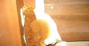
The photo shows a wind wheel with broken blades. These blades were made of thin PVC pipe (for pressureless sewage). They caved in from the pressure of the wind and crashed onto the mast.
|
|
|
|


The calculation of the optimal shape of the blade is quite complicated and there is no need to bring it here, let the professionals do it. It is enough for us to make the blades using the already calculated template according to Fig. 2, which shows the dimensions of the template in millimeters. You just need to cut such a template out of paper (photo of the blade template on a 1: 2 scale), then attach 160 mm to the pipe, draw a outline of the template on the pipe with a marker and cut the blades using an electric jigsaw or manually. Red dots in fig. 2 shows the approximate location of the mountings of the blades.
As a result, you will have to get six blades, the shape as in the photo. In order for the resulting blades to have a higher KIEV and produce less noise during rotation, sharp edges and edges must be sharpened, and all rough surfaces must be sanded.


To fasten the blades to the body of the bicycle motor, you need to use the head of the wind turbine, which is a mild steel disk 6-10 mm thick. Six steel strips 12 mm thick and an assembly length of 30 cm with holes for attaching the blades are welded to it. The disk is attached to the casing of the cycle motor with bolts with locknuts for the holes for fixing the spokes.


After the manufacture of the wind wheel, it must be balanced. For this, the wind wheel is fixed at a height in a strictly horizontal position. It is advisable to do this indoors, where there is no wind. With a balanced wind wheel, the blades should not rotate spontaneously. If any blade is heavier, it needs to be grinded from the end to balance in any position of the wind wheel.
It is also necessary to check whether all the blades rotate in the same plane. To do this, measure the distance from the end of the lower blade to some nearest object. Then the wind wheel turns and measures the distance from the selected object to the other blades. The distance from all blades should be within +/- 2 mm. If the difference is greater, then the skew should be eliminated by bending the steel strip to which the blade is attached.
Fastening the generator (cycle motor) to the frame
Since the generator experiences heavy loads, including from gyroscopic forces, it should be securely fixed. The cycle motor itself has a strong axis, since it is used at high loads. So, its axis must support the weight of an adult under dynamic loads that arise when riding a bicycle.
But on the bicycle frame, the bicycle motor is mounted on two sides, and not on one side, as it would when working as a current generator for a wind power station. Therefore, the shaft must be attached to the frame, which is a metal part with a threaded hole for screwing onto the shaft of the bicycle motor of the corresponding diameter (D) and four mounting holes for mounting the M8 steel bolts to the frame.

It is advisable to use the largest possible length of the free end of the shaft for mounting. To prevent the shaft from rolling in the bed, it must be secured with a nut and a counter washer. The bed is best made of duralumin.
 For the manufacture of a wind generator frame, that is, the base on which all other parts will be located, it is necessary to use a steel plate with a thickness of 6-10 mm or a section of a channel of suitable width (depends on the outer diameter of the rotary assembly).
Production of a current collector and a rotary assembly
If you simply tie the wires to the generator, then sooner or later the wires will twist when the windmill rotates around the axis and break. To avoid this, you need to use a movable contact - a current collector, which consists of a sleeve made of insulating material (1), contacts (2) and brushes (3). To protect against rainfall, the current collector contacts must be closed.
For the manufacture of a wind generator current collector, it is convenient to use this method: first, on the finished rotary assembly, contacts are placed, for example, of thick brass or copper wire of rectangular cross section (used for transformers), the contacts should already be with soldered wires (10), for which one must be used - or stranded copper wire with a cross section of at least 4 mm 2. The contacts are covered with a plastic cup or other container, the hole in the support sleeve (8) is closed and filled with epoxy. The photo used epoxy resin with the addition of titanium dioxide. After hardening of the epoxy resin, the part is grinded on a lathe until the contacts appear.

As a moving contact, it is best to use copper-graphite brushes from a car starter with flat springs.


In order for the wind wheel of the wind generator to rotate in the wind, it is necessary to provide a movable connection of the wind turbine frame with a fixed mast. The bearings are located between the support sleeve (8), which is connected via a flange to the mast pipe with bolts and a sleeve (6), which is welded by arc welding (5) to the frame (4). To facilitate rotation, you need a rotary assembly using bearings (7) with an internal diameter of at least 60 mm. Roller bearings that are better able to absorb axial loads are best suited.
 Protecting a Wind Farm from Hurricane Winds
The maximum wind speed at which this wind farm can be operated is 8–9 m / s. If the wind speed is greater, the operation of the wind farm should be limited.
Of course, this proposed type of do-it-yourself windmill is slow-moving. It is unlikely that the blades will spin up to extremely high revolutions at which they collapse. But if the wind is too strong, the pressure on the tail of the plumage becomes very significant, and with a sharp change in the direction of the wind, the wind generator will turn sharply.
Considering that the blades rotate quickly during strong winds, the wind wheel turns into a large heavy gyroscope that resists any bends. That is why significant loads arise between the frame and the wind wheel, which focus on the generator shaft. There are many cases when amateurs built wind turbines with their own hands without any protection against hurricane winds, and because of significant gyroscopic forces, the durable axles of automobile generators broke.
In addition, a six-hazard wind turbine with a diameter of 2 m has significant aerodynamic drag, and with a strong wind it will significantly load the mast.
Therefore, in order for a home-made wind generator to serve for a long time and reliably, and the wind wheel does not fall on the head of passers-by, it is necessary to protect it from hurricane winds. The easiest way to protect the windmill with a side shovel. This is a fairly simple device that has proven itself in practice.
 The work of the side shovel is as follows: with a working wind (up to 8 m / s), the wind pressure on the side shovel (1) is less than the stiffness of the spring (3), and the windmill is installed approximately in the wind by means of plumage. In order to prevent the spring from folding the windmill with a working wind more than is necessary, a tie (4) is stretched between the tail (2) and the side shovel.
When the wind speed reaches 8 m / s, the pressure on the side shovel becomes stronger than the force of the spring, and the wind generator begins to add up. In this case, the wind flow begins to run onto the blades at an angle, which limits the power of the wind wheel.
With a very strong wind, the windmill develops completely, and the blades are installed parallel to the direction of the wind, the operation of the windmill practically stops. Please note that the tail is not rigidly connected with the frame, but rotates on a hinge (5), which must be made of structural steel and have a diameter of at least 12 mm.
The dimensions of the side shovel are shown in Fig. 1. The side shovel itself, as well as the plumage, is best made from a profile pipe 20x40x2.5 mm and a steel sheet 1-2 mm thick.
As a working spring, you can use any carbon steel springs with a protective zinc coating. The main thing is that in the extreme position the spring force is 12 kg, and in the initial position (when the windmill has not yet folded) - 6 kg.
To make a banner, you should use a steel bicycle cable, the ends of the cable are bent into a loop, and the free ends are fixed with eight turns of copper wire with a diameter of 1.5-2 mm and soldered with tin.

Windmast mast
As a mast for a wind farm, you can use a steel water pipe with a diameter of at least 101-115 mm and a minimum length of 6-7 meters, provided that it is relatively open area, where at a distance of 30 m there would be no obstacles to the wind.
If a wind farm cannot be installed in an open area, then there is nothing to be done. It is necessary to increase the height of the mast so that the wind wheel is at least 1 m higher than the surrounding obstacles (houses, trees), otherwise the generation of electricity will significantly decrease.
The mast base itself should be installed on a concrete platform so that it does not squeeze into wet soil.
As extensions, you must use galvanized steel mounting cables with a diameter of at least 6 mm. Stretch marks are attached to the mast by means of a clamp. At the ground, the cables are attached to strong steel pegs (from a pipe, channel, corner, etc.), which are buried in the ground at an angle to a full depth of one and a half meters. It is even better if they are additionally monolithic at the base with concrete.


Since the mast assembly with the wind generator has considerable weight, for manual installation it is necessary to use a counterweight made of the same steel pipe as the mast or a wooden beam 100x100 mm with a load.

Electric scheme of a wind power station
The figure shows the simplest battery charging scheme: the three outputs from the generator are connected to a three-phase rectifier, which is three half-bridge diode connected in parallel and connected by a star. Diodes must be rated for a minimum operating voltage of 50V and a current of 20A. Since the maximum operating voltage from the generator will be 25-26 V, the leads from the rectifier are connected to two 12 volt batteries connected in series.
Using this simplest scheme, the batteries are charged as follows: at low voltage less than 22 V, the batteries are very weakly charged, since the current is limited by the internal resistance of the batteries. At a wind speed of 7-8 m / s, the generated voltage of the generator will be in the range of 23-25 \u200b\u200bV, and the intensive process of charging the batteries will begin. At higher wind speeds, the operation of the wind generator will be limited to a side shovel. To protect the batteries (during emergency operation of a wind farm) from excessive strong current, the circuit must have a fuse rated for a maximum current of 25 A.
As you can see, this simple scheme has a significant drawback - in case of a quiet wind (4-6 m / s), the battery will not be practically charged, and it is precisely such winds that are most often found on flat terrain. In order to recharge the batteries in light winds, you need to use a charge controller that connects in front of the batteries. The charge controller will automatically convert the required voltage, also the controller is more reliable than a fuse and prevents overcharging of batteries.


In order to use rechargeable batteries to power household appliances designed for an alternating voltage of 220 V, an additional inverter will be needed to convert a DC voltage of 24 V to the appropriate power, which is selected depending on the peak power. For example, if you connect lighting, a computer, a refrigerator to an inverter, then an inverter designed for 600W is quite enough, but if you plan to use an electric drill or a circular saw (1500 W) at least occasionally, you should choose an inverter with a power of 2000 W.
 The figure shows a more complex electrical circuit: in it, the current from the generator (1) is first rectified in a three-phase rectifier (2), then the voltage is stabilized by the charge controller (3) and charges the 24 V batteries (4). An inverter (5) is connected to power household appliances.
The currents from the generator reach tens of amperes, therefore, to connect all the devices in the circuit, copper wires with a total cross section of 3-4 mm 2 should be used.
It is advisable to take a battery capacity of at least 120 a / h. The total battery capacity will depend on the average wind intensity in the region, as well as on the power and frequency of the connected load. More precisely, the required capacity will be known during the operation of the wind farm.
Wind Farm Care
The considered low-speed wind generator for DIY manufacture, as a rule, starts well in light winds. For the normal operation of the wind generator as a whole, you must adhere to these rules:
1. Two weeks after starting, lower the wind generator in light wind and check all fasteners.
The increase in user interest in alternative sources of electricity is understandable. The lack of opportunities for connecting to centralized networks forces the use of other methods of providing housing or temporary points of residence with electricity. The share is constantly growing, since the acquisition of an industrial design is very expensive and always quite effective.
When creating a windmill, the possibility of heavy gusts of wind should be taken into account and appropriate measures should be taken to protect the structure from them.
What is strong wind protection for?
Wind generator Designed for a specific wind strength. Typically, averages typical of a given region are taken into account. But when the wind flow is strengthened to critical values, which sometimes happens in any area, there is a risk of the device breaking down, and in some cases, complete destruction.
Equipped with protection against such overloads, either by current (when the permissible voltage value is exceeded, an electromagnetic brake is activated) or by rotation speed (mechanical brake). Home-made designs also need to be equipped with similar devices.
Impellers, especially equipped, at high speeds of rotation begin to act on the principle of a gyroscope and retain the plane of rotation. Under such conditions, the tail cannot do its job and orient the device along the flow axis, which leads to breakdowns. This is possible even if the wind speed is not too high. Therefore, a device that slows down the progress of the impeller is a necessary structural element.
Is it possible to make the device with your own hands?
Manufacturing devices is quite possible. Not only that, it is an absolute must. Brake device should be provided at the design stage of the windmill. The operation parameters of the device must be calculated as carefully as possible so that its capabilities do not turn out to be too low compared to the actual design needs.
First of all, you need to choose the method of implementation of the brake device. Usually simple and trouble-free mechanical devices are used for such structures, but electromagnetic samples can also be created. The choice depends on which winds prevail in the region and what is the design of the windmill itself.
The easiest option is to manually change the rotor axis direction. To do this, you only need to install a hinge, but the need to go out into the street with a strong wind is not the best solution. In addition, it is not always possible to manually stop, since at this moment you can be far from home.
Operating principle
There are several mechanical methods for impeller braking. The most common options for horizontal wind turbine designs are:
- withdrawal of the rotor from the wind using a side blade (stop by folding tail method);
- rotor braking with a side blade.
Vertical structures are usually braked by means of weights mounted on the outer points of the blades. When the rotation speed increases, they begin to press on the blades under the action of centrifugal force, forcing them to fold or turn sideways to the wind, which makes the rotation speed decrease.
Attention! This method of braking is simple and most effective, allows you to adjust the speed of rotation of the impeller, but is applicable only for vertical structures.
Tail folding protection method
The device, carrying out the removal of the wind by folding the tail, allows you to smoothly and fairly flexibly control the speed of rotation of the rotor. The principle of operation of such a system is to use a side lever mounted in a horizontal plane perpendicular to the axis of rotation. The rotating impeller and lever are rigidly connected, and the tail is attached through a spring-loaded swivel joint acting in a horizontal plane.
At nominal values \u200b\u200bof wind force, the side lever is not able to move the rotor to the side, since the tail guides it in the wind. With increasing wind pressure on the lateral blade increases and exceeds the force of the spring. In this case, the rotor axis is turned away from the wind, the effect on the blades decreases and the rotor slows down.
other methods
The second method of mechanical braking is close in design, but the side blade acts differently - when the wind intensifies, it starts to press on the rotor axis through special pads, slowing its rotation. At the same time, the rotor and tail are mounted on the same shaft, and the articulation with the spring is applied on the side lever.
At normal wind speeds, the spring holds the lever perpendicular to the axis, when amplified, it begins to deviate towards the tail, pressing brake pads to the axis and inhibiting rotation. This option is good for small blade sizes, since the force exerted on the shaft to stop it should be quite large. In practice, this option is used only at relatively low wind speeds, with heavy gusts the method is ineffective.
In addition to mechanical devices, electromagnetic ones are widely used. With increasing voltage, a relay starts to attract brake pads to the shaft.
Another option that can be used for protection is to open the circuit when too high a voltage occurs.
Attention! Some methods provide only protection of the electrical part of the complex, without affecting the mechanical structural elements. Such methods are not able to ensure the integrity of the windmill in the event of sudden squall winds and can only be used as additional measures, acting in conjunction with mechanical devices.

Protection scheme and drawings
For a more visual representation of the principle of operation of the brake device, we consider the kinematic scheme.

The figure shows that the spring in the normal state keeps the rotating assembly and tail on the same axis. The force created by the wind flow overcomes the resistance of the spring with increasing speed and gradually begins to change the direction of the axis of the rotor, the wind pressure on the blades decreases, due to which the rotation speed drops.
This scheme is the most common and effective. It is simple in execution, allows you to create a fixture from improvised materials. In addition, the adjustment of this brake is simple and comes down to selecting a spring or adjusting its force.

Attention! The maximum angle of rotation of the rotor is not recommended to do more than 40-45 °. Large angles contribute to the complete stop of the windmill, which then hardly starts up with uneven squally winds.
Calculation Procedure
Calculation of the brake device quite complicated. He will need various data, which is not easy to find. It is difficult for an unprepared person to make such a calculation; the probability of errors is high.
Nevertheless, if independent calculation is necessary for any reason, you can use the formula:
P x S x V 2 \u003d (m x g x h) x sinαwhere:
- P is the force applied to the propeller by the wind flow,
- S is the area of \u200b\u200bthe propeller blades,
- V is the wind speed,
- m is the mass
- g is the acceleration of gravity (9.8),
- h is the distance from the hinge to the point of attachment of the spring,
- sinα is the angle of inclination of the tail relative to the axis of rotation.
It should be borne in mind that the values \u200b\u200bobtained by independent calculations require a correct interpretation and a full understanding of the physical essence of the process that occurs during rotation. In this case, they will not be quite correct, since the subtle effects accompanying the operation of the wind turbine will not be taken into account. However, the values \u200b\u200bcalculated in this way will be able to give the order of magnitude necessary for the manufacture of the device.
The process of creating a wind generator It is accompanied by a mass of expenses and requires a variety of different actions, which in itself forces us to protect the structure as much as possible from the possibility of destruction. If there is a foreseeable danger of destruction or failure of the complex, then the creation and use of protective devices should not be neglected in any case.
Between the leading economies of the world there was a competition in the field of space exploration. During a conversation with reporters, the head of the Russian space agency Roscosmos, Dmitry Rogozin, spoke about the nearest promising developments and plans of the company, among which the plan to create a landing ... Read more