Schemes for the production of work by bulldozers. Bulldozer erection of earthworks Bulldozers for backfilling of the brand
Schemes for the production of work by bulldozers
There are three main schemes for the development and movement of soil by bulldozers: straight, side and stepped.
The direct scheme is used when digging trenches and notches, the width of which slightly exceeds the width of the bulldozer blade; when arranging entrances, when soil dumping is allowed in one place. Working according to this scheme, the bulldozer, when developing and moving the soil, moves in a straight line, making a reciprocating motion without turns. This pattern of movement of bulldozers is often called pendulum. When moving forward, the bulldozer cuts the soil at a certain section of the path, and then transports it to the place of the dump (working stroke). Then it returns to the place where it starts cutting the soil, moving in reverse (idle). The number of working and idling strokes of the bulldozer depends on the design depth of the excavation and the thickness of the soil shavings cut during one pass.
The side scheme of the bulldozer is used when moving previously developed soil from dumps or bulk materials (sand, gravel, etc.) from bunkers, when developing light soils cut off with thick layers, as well as when working on slopes. In this case, the excavated soil is located on the side of the path along which the bulldozer transports it to the dumping site. The bulldozer grabs the soil with the blade, makes a turning movement, moving the soil onto the transport path, and then transports it to the dumping site. Only a qualified bulldozer operator can work in a side pattern, since with insufficient experience in driving a bulldozer, a significant part of the soil can be lost when turning the bulldozer.
The stepwise scheme of the development and movement of soil is used mainly when arranging embankments, performing stripping operations and vertical leveling of areas, when it is allowed to fill the excavated soil over the entire width of the excavation. Working according to this scheme, the bulldozer develops the soil with parallel penetrations. Having moved the soil from one penetration, the bulldozer idles at an angle to the axis of the working stroke and begins the development and movement of the soil on the adjacent penetration (Fig. 96).

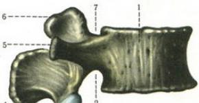
Rice. 96. Scheme of erection of an embankment by a bulldozer
1 - direction of the working stroke of the bulldozer; 2 - center pegs; 3 - high-altitude landmarks; 4 - dumped soil layers; 5 - direction of idling of the bulldozer; 6 - the direction of the working stroke of the bulldozer
The considered methods of development and movement of soil are used to a greater or lesser extent in almost all earthworks performed by bulldozers. Specific examples of the organization of bulldozing works on various earthworks are considered below.
When performing stripping works with soil filling into a previously worked-out area, soil development is carried out by crossing penetrations, inclined towards the working under a coal of 10 ... 12 °. The development of soil begins in areas located in the immediate vicinity of the upper edge of the slope of the old working. In this case, the thickness of the cut soil layer is increased as the bulldozer approaches the working, so that it is maximum at its slope.
The vertical leveling of areas with the help of bulldozers is carried out after the breakdown of the entire area, indicating the depth of soil removal in high areas and the height of filling it in the grooves. The soil is developed by parallel penetrations. In this case, it is advisable to use a combined soil development and movement scheme, combining direct and stepped schemes.
The erection of embankments with bulldozers without the use of other machines (rollers, watering machines) is allowed only in cases where the technical conditions for the production of work do not provide for soil compaction and local data allow the use of soil from reserves.
Depending on the width of the embankment, soil development is carried out in one- or two-sided lateral reserves. The embankment is erected in the following technological sequence. Before starting work, a geodetic breakdown of the embankment and lateral reserves is performed, the purpose of which is to outline the axis and boundaries of the embankment base, the berm and reserves boundaries. The reserves are laid mainly on the upland side of the embankment with a transverse bilateral bottom slope of 0.02 to the middle of the reserve. The longitudinal slope of the bottom of the reserve should be not less than 0.002 and not more than 0.008. For the convenience of work, filling of the embankment is carried out with grapples 50 ... 100 m long.
The development of the soil begins from the field edge of the reserve. Moving at first speed, the bulldozer cuts the soil in layers up to 30 cm and moves it towards the embankment. When approaching the berm, the bulldozer blade is gradually raised so as not to cut the soil on the berm. The soil is laid in the body of the embankment with rollers, placing them along the width of the embankment. The idling of the bulldozer in reserve is carried out at the maximum reverse speed.
The soil from each penetration in the reserve is laid into the body of the embankment, placing it along the width of the embankment, after which the bulldozer begins to develop the soil on the next boring with rollers. After filling the first layer of the embankment along the entire length of the grasp, the bulldozer rises to the embankment and, moving along the structure, levels the soil laid by rollers, at the same time compacting it with caterpillars. The bulldozer performs the filling of the subsequent layers of the embankment in the same sequence. Having finished filling the embankment to the specified height, the bulldozer evens out the topsoil, plans berms and the bottom of the reserve, bringing the longitudinal and transverse slopes to the design marks.
The filling of embankments with a height of 1.5 ... 2 m can be done without layer-by-layer leveling of the filled soil at once to the full height. In this case, the working mark of the embankment should be increased against the design by 10 ... 15%, since the embankment will settle for a long time after the completion of construction.
During the construction of a roadbed on slopes, the soil is developed and moved in a semi-heap by the longitudinal and transverse moves of the bulldozer. On slopes with a transverse slope of 8 ... 10 °, it is advisable to develop the soil with longitudinal moves. In this case, the bulldozer moves the soil into the shafts located along the entire width of the half-cut. In the future, the bulldozer transports the soil from the shafts to the semi-heap, moving at an angle to the axis of the roadbed under construction. On slopes with a transverse slope of 12. ... 20 °, soil development is carried out with transverse penetrations, on which the bulldozer moves perpendicular to the axis of the track under construction. This allows you to increase the productivity of the bulldozer by increasing the thickness of the cut soil layer, since the bulk of the soil moves downhill.
Before moving the soil into the semi-fill, the slope surface, which is the basis for the semi-fill, is loosened or cut by a bulldozer ledges. To protect the roadway from the influence of surface water from the upland side, a trenching ditch or a bulldozer, to the dump of which a special nozzle is attached, tear off a drainage ditch.
Backfilling of the trench with a bulldozer is carried out with soil from a dump located along the trench in the following technological sequence. After laying a pipeline, cable or device of another structure, it is simultaneously filled up from both sides manually (so as not to damage or displace the pipeline or structure to be filled in) to a height of 0.25 ... 0.3 m above the top of the structure. Further backfilling of the trench is carried out by a bulldozer, moving in cross transverse paths.
The dump area is divided into separate sections, the bulldozer approaches the soil dump at a certain angle, picks up the soil in section I and moves it into the trench. After that, with transverse penetrations, he moves the soil into the trench from section II, then oblique penetrations from section III, transverse from section IV, etc. A similar scheme of movement of the bulldozer is used when backfilling the foundations of buildings. With such an alternation of the directions of movement of the bulldozer, the path of its movement with the ground decreases and the conditions for collecting soil are improved.
Backfilling of an artificial structure, the design of which does not require manual backfilling (reinforced concrete collectors, tunnels, large-diameter pipes, etc.), is carried out in the following order. First, the structure is sprinkled on one side to a height of up to 0.5, then it is sprinkled to a height of 1 m on the other side with soil brought by dump trucks. The final backfilling of the structure to its full height (after it has been backfilled on both sides) is performed as indicated above. Compliance with this sequence of backfilling is necessary, since with one-sided backfilling, deformation of the structure is possible.
When cleaning slopes with bulldozers, soil dumps are placed mainly along the lower edge of the slope being cleaned. This allows the soil to be moved from top to bottom. With the help of bulldozers, slopes are cleaned, the steepness of which does not exceed 1: 2.5.
In some cases, it is allowed to clean the slopes with the movement of soil up the slope. The organization of work according to this scheme is advisable in areas where the bulk of work on cleaning the slopes is performed by excavators or other machines, and bulldozers only clean up and level the slopes.
TO Category: - Mechanization of earthworks
|
|
|
LOCAL RESOURCE STATEMENT GESN 29-02-026-03
| Name | unit of measurement |
| Backfilling with soil (sand) with a bulldozer with pneumatic rollers compaction of tunnel ceilings in pits with fastening and slopes | 100 m3 of backfill material |
| Scope of work | |
| 01. Reception of material for backfilling from dump trucks at the storage site with subsequent feeding under the excavator by a loader. 02. Supply of backfill material with an excavator with a grab to the backfill site. 03. Moving the backfill material with a bulldozer at a distance of 50 m. 04. Compaction of the backfill material with a roller in 8 passes. 05. Watering the backfill material. | |
PRICE VALUES
The price takes into account the PZ of work on year 2000(Moscow prices), calculated according to the HESN sample 2009 year... The indexation of the translation into current prices must be applied to the cost.
You can go to the pricing page, which is calculated based on the standards of the 2014 edition with additions 1
GESN-2001 was used to determine the composition and consumption of materials, machines and labor costs.
EMPLOYMENT
| № | Name | Unit Rev. | Labor costs |
| 1 | Labor costs of construction workers Category 3.8 | person-h | 2,34 |
| 2 | Labor costs of drivers (for reference, included in the price of EM) | person-h | 9,97 |
| Total labor costs of workers | person-h | 2,34 | |
| Workers' wages = 2.34 x 9.4 | Rub. | 22,00 | |
| Remuneration for machinists = 134.16 (for calculating invoices and profits) | Rub. | 134,16 | |
OPERATION OF MACHINES AND MECHANISMS
| № | Cipher | Name | Unit Rev. | Consumption | St-st unit. Rub. |
Total Rub. |
| 1 | 070150 | Bulldozers for other types of construction 96 kW (130 hp) | machine-h | 3,25 | 94,21 | 306,18 |
| 2 | 120910 | Pneumatic rollers 16 t | machine-h | 3,36 | 156,32 | 525,24 |
| 3 | 121601 | Watering machines 6000 l | machine-h | 3,36 | 110 | 369,60 |
| Total | Rub. | 1 201,02 | ||||
CONSUMPTION OF MATERIALS
| № | Cipher | Name | Unit Rev. | Consumption | St-st unit. Rub. |
Total Rub. |
| 1 | 407-9085 | Priming | m3 | 110 | 0 | 0,00 |
| 2 | 411-0001 | Water | m3 | 10 | 2,44 | 24,40 |
| Total | Rub. | 24,40 | ||||
TOTAL BY RESOURCES: RUB 1,225.42
A bulldozer is an earth-moving vehicle that performs development, transport, backfilling and leveling of the soil (Fig. 2.42). However, when a bulldozer is operating, unlike a scraper, the developed soil does not move in a bucket, but drags along the ground, pushed by a working body - a knife. The volume of the pushed soil (drag prism) depends on the size of the knife, which, in turn, determines the required energy (engine power of the base machine).
1. Type of product: site planning, construction of shallow (up to 3 m) foundation pits, low (up to 3 m) embankments, reworking the soil in the foundation pit after the excavator, backfilling of trenches and pits. The latter processes are carried out mainly with the help of bulldozers.
2. The composition of the process: cutting the soil, transporting (dragging) the soil, filling, leveling, returning (idling) (Fig. 2.43).
3. Entry to the process is general (see page 29).
4. Resources.
4.1. Materials - soils of groups I – II of natural constitution; loosened soils of III-IV groups.
4.2. Technique: bulldozers. They are distinguished by the base: caterpillar - have a large tractive effort; wheeled - more mobile and do not require special transport for delivery to the object. The main technological parameters of the bulldozer are the dimensions of the knife (blade), which determine its performance.
The knife can be fixed rigidly - uncontrollable, it is possible to have a knife control system (turning through a certain angle) in the horizontal and vertical plane (Fig. 2.44).
5. Process technology.
The scheme of the bulldozer can be: shuttle, shuttle with offset, zigzag, side penetration (with backfilling) (Fig. 2.45). The rational distance of soil transport is 10–40 m, in some cases up to 70 m. When using special technologies: trenching, frontal passage - up to 100 m.
 |
 |
| Rice. 2.44. Development and leveling of soil by a bulldozer: a - moving the blade in a vertical plane; b - installation of the blade in plan at an angle to the longitudinal axis of the bulldozer; c - the same, at an angle to the horizontal plane; d - slope grading with a bulldozer equipped with a slope blade; 1 - tractor; 2 - hydraulic cylinder or rope pulley; 3 - blade; 4 - slope planner blade |
 |
 |
Development of pits is carried out on one side (Fig. 2.46, a), and at large sizes, to reduce the distance of transportation, development is carried out from the center to two sides (Fig. 2.46, b; 2.47).
The filling of soil into the embankment is carried out in layers, alternating with compaction, the thickness of the layer is set by the capacity of the compaction mechanism and is 0.3–1.0 m. If necessary, intermediate moistening of the soil of each layer is carried out (Fig. 2.47).
Backfilling of trenches and sinuses of foundation pits is also carried out in layers, alternating backfilling of the layer and its compaction. After filling, the soil layer is wetted for effective compaction.
When backfilling pipelines before the work of the bulldozer, two operations are performed manually: backfilling of soil (tamping) under the pipe and backfilling of the pipe with a layer of soil of 30–50 cm. After manual operations, the bulldozer begins to "dump" the soil into the trench. When backfilling collectors, reinforced concrete trays of heating mains, etc. backfilling is carried out alternately: first on one side to a height of 0.5 m, then on the other to a height of 1.0 m and further, alternating by 1.0 m. The sinuses of the retaining walls are backfilled in horizontal layers along the entire length of the wall or its section.
 |
 |
| Rice. 2.50. Backfilling by moving a bulldozer with an inclined blade: 1 - dumping soil for backfilling the trench; 2 - filling the soil manually; 3 - the direction of movement of the bulldozer 1; 2; …five |
All city backfills should be backfilled with sand only as soil with minimum settlement.
To increase the performance of the bulldozer, the following schemes are used:
Cutting and dragging the soil when moving the bulldozer downhill. Increase in productivity by 3-5% (Fig. 2.51);
To hold a large amount of soil pushed by the bulldozer, openers are installed on the knife. Increase in productivity by 7-15% (Fig. 2.51);
Frontal stroke (work) of two or three bulldozers. This allows you to significantly increase the volume of the drawing prism and increase productivity by 30–70%. However, this requires highly qualified machinists who ensure the synchronous operation of two or three bulldozers (Fig. 2.52);
Trenching. Here, the trench walls keep the soil on the blade, and the bulldozer transports the maximum amount of soil possible for a given engine power. The walls can form naturally during the operation of the bulldozer due to the soil lost on the sides of the blade (Fig. 2.53), as well as from undeveloped soil when driving two or three bulldozers in parallel with a certain distance between them.
 |
 |
 |
In the conditions of a construction site, the bulldozer performs the leveling of roads, tracks for tower cranes, the leveling of soil, sand dumped by dump trucks, as well as the arrangement of ramps into pits, etc.
Technology Assessment. Based on the type of erected earthen structure, the availability of specific equipment and a given distance of transportation, an approximate estimate of the costs of soil development can be performed according to table. 2.3.

Source: Technology of construction processes. Snarskiy V.I.
STANDARD TECHNOLOGICAL MAP (TTC) BACKFILLING, LEVELING AND COMPACTING OF SOIL IN A TRANCH WITH A COLLECTOR 1. SCOPE The technological map (TK) is compiled for the production of backfilling, leveling and compaction of a group of I group of soil with a length of II optimal number of storeys in a trench with a depth of 3 m and with a collector 1.8 m wide and 1.9 m high.When linking the TC to a specific object and construction conditions, clarify the work flow diagrams, scope of work, cost estimates, labor costs, mechanization tools, taking into account the maximum use of the park mechanisms. GENERAL PROVISIONS 1. Technical recommendations apply to work on soil compaction during backfilling of pits, trenches, sinuses after laying underground engineering networks, and making foundations for buildings under construction. 2. Technical recommendations also apply to work on soil compaction after restoration of underground engineering networks in the area of the roadway. 3. Soil compaction should be carried out in accordance with SNiP 3.02.01-87 "Earth structures, foundations and foundations" and VSN 52-96 "Instructions for earthworks in road construction and when installing underground engineering networks". 4. Characteristics, terms and definitions of soils are used in accordance with GOST 25100-95 "Soils. Classification". BACKFILLING TECHNOLOGY WITH TRANCHES 1. Backfilling of engineering communications trenches is carried out after testing them and issuing an act, performing insulation of joints, channels, niches and obtaining permission to carry out backfilling. 2. Backfilling of trenches for underground utilities with soil must be carried out after the laying of pipelines and network devices, it is also necessary to take measures against their displacement along the axis and against damage to pipelines and their insulation. A diagram of soil compaction during backfilling of trenches, a diagram of the organization of work on backfilling of trenches and a diagram of backfilling of trenches are shown in Fig. 1, 2, 3, respectively. Fig. 1. Diagram of soil compaction when backfilling trenches: 1 - area above the pipeline, where soil compaction is prohibited; 2, 3 - the thickness of the soil layer compacted by hand mechanisms; 4 - a layer of soil compacted with a non-mechanized hand tool; 5 - soil layers, compacted with mechanical rammers (taken up to 0.25 m); - thickness of the compacted layer, seal on both sides simultaneously Note. Non-mechanized hand tools - shovel, scoop, wooden rammers; manual mechanisms - platform vibrators, electric rammers, mechanical rammers. Fig. 2. The scheme of the organization of works on backfilling of trenches: a) by excavator-planner; b) a bulldozer; 1 - excavator-planner; 2 - backfilling of soil with a bulldozer; 3 - backfilling of soil by excavator-planner; 4 - leveling the soil with an excavator planner; 5 - manual leveling of the soil; 6 - polyvinyl chloride pipe; 7 - soil for backfilling; 8 - bulldozer; 9 - sewer well The distance from the trench slope line to the beginning of the dump of soil along the edge of the trench should be at least 0.7 m at a trench depth of up to 3 m and at least 1.0 m at a trench depth of more than 3 m. Fig.3. Backfilling scheme of trenches: a) telephone sewerage; b) channelless heating network; 1 - soil layers compacted by manual electric rammers; 2 - layers of soil filled in and compacted manually; 3 - plastic pipes; 4 - drainage pipe (pipe filter, etc.); 5 - pipelines; I - soil layers compacted with light mechanical rammers; II - soil layers compacted by manual electric rammers; III - layers of soil, filled up and compacted manually 3. Backfilling of trenches with laid underground utilities is carried out in two stages. First, the sinuses are filled in and knocked out manually, and the pipelines are sprinkled to a height above the top of the pipeline of at least 0.2 m with careful layer-by-layer manual ramming, and in the winter time for ceramic, asbestos-cement and polyethylene pipes - 0.5 m. The rest of the trench is then backfilled by carefully bulldozing the soil. 4. Layer-by-layer compaction of backfill pipelines is performed mainly by pneumatic, motor, electric rammers, as well as by vibration compaction. 5. The sinuses between the pipe and the walls of the trench are filled up layer by layer with excavators-planners EO-3532A, excavators EO-2621V, EO-3123, EO-4225, etc .; the layer thickness should be no more than 0.25 m. Compaction is made evenly on both sides by electric rammers of the IE-4502A type. 6. When compaction of soil over communications, the thickness of the protective layer must be at least 0.25 m for metal and reinforced concrete pipes and at least 0.4 m for ceramic, asbestos-cement and plastic pipes. The protective layer above the communications is also compacted with electric rammers. 7. When laying cable lines, trenches should be backfilled from below, and from above - backfilled with a layer of shallow earth that does not contain stones or construction waste. The thickness of the sand layer for backfill and the thickness of the backfill layer must be at least 0.1 m. 8. When backfilling pipelines laid in trenches with a slope of more than 20 °, it is necessary to take measures against soil slipping and its erosion by storm water. The method of strengthening must be indicated in the project for the production of works. 9. When laying pipes made of polyethylene, the bottom of the trench is leveled, and in rocky soils it is necessary to arrange a pillow of loose soil with a thickness of at least 0.1 m without the inclusion of stones, gravel, etc. after their preliminary density test. 11. Further backfilling of soil over the laid pipelines is carried out by excavators, excavators-planners, bulldozers in layers with a layer thickness of 0.7 m for sand, 0.6 m for sandy loam and loam, 0.5 m for clay. Layer-by-layer soil compaction is carried out with hydraulic hammers and vibrating plates. 12. Backfilling of the trench with soil using a bulldozer is shown in Fig.4. It can be seen from the figure that the area of the dump from which the soil is taken is divided into separate, successively developed areas. The bulldozer approaches the edge of the dump from its end at a certain angle, picks up the soil in section I and, after moving it into the trench, goes to the next section II. The soil from sections II, IV, VI is moved into the trench by transverse passes of the bulldozer, and from sections I, III, V, VII - oblique. This method of work reduces the length of the loaded bulldozer passes and improves the conditions for soil collection. Fig. 4. Backfilling of the trench with soil using a bulldozer: 1 - bulldozer; 2 - pipeline 13. When the route passes along buildings, fences, green spaces, the trench is backfilled manually with layer-by-layer compaction of the backfill every 0.2 m. 14. Trenches and pits at the intersection with existing or projected roads should be filled with sand to the full depth and compacted up to - 0.98. 15. Compaction of the upper layers by 1.0-1.2 m from the surface can be carried out by trailed rollers to tractors T-150 (SD-801) and self-propelled tractors of various types weighing 6-15 tons (DU-47B, DU-64, DU- 58A, etc.) 16. At the intersection of trenches with existing underground utilities (pipelines, cables, etc.) passing within the depth of the trenches, the project should provide for devices that ensure the invariability of the position and safety of communications for the period of work and operation. If such devices are not provided, backfilling of trenches should be carried out in the following order: backfilling under existing communications is performed with sand along the entire cross-section of the trench to a height of up to half the diameter of the pipeline (cable) or its protective sheath with layer-by-layer compaction; along the trench, the size of the backfill along the top should be 0.5 m larger on each side of the pipeline (cable) or its protective sheath, and the slope of the backfill should be 1: 1. 17. The performed works on soil compaction shall be presented to the author's and technical supervision and draw up an act for hidden works. 18. Backfilling and compaction of ditches, trenches, sinuses, over which rail tracks for the installation of tower cranes should be built, should be done in the same way as the foundation made of bulk soil. 19. The fill soil of the subgrade should be laid in layers with compulsory layer-by-layer compaction. The thickness of the layers is determined by the machines and mechanisms used to compact the soil. 20. Density (volumetric weight of the skeleton) of the subgrade soil in g / m should be at least for: fine and dusty sands - 1.7; sandy loam - 1.65; loam - 1.6; clay - 1.5. 21. When constructing rail tracks with wooden half-sleepers, the density of the soil should be checked every 12.5 m, and when constructing tracks with reinforced concrete beams - under each beam. 22. The results of the check must be entered into the act of putting the rail track into operation. 23. Recommended machines and equipment for backfilling of pits, trenches, sinuses, soil compaction are given in Table 1.1. Table 1.1
Note. The need for machines is determined by the project for the production of work, depending on the design solutions of structures, the amount of work and the duration of their implementation. 24. At negative air temperatures, the compaction of the backfill soil in the trenches should be carried out until the compaction coefficient of 0.98 is reached. 25. The time of soil compaction depending on the air temperature is indicated in Table 1.2. Table 1.2 26. The following methods are recommended for layer-by-layer compaction of backfills: for non-cohesive soils - vibration and vibratory ramming; for loosely connected soils - rolling, ramming, vibratory ramming, vibration; for cohesive soils - rolling, tamping, vibratory ramming and combined. 27. Compaction of the soil in cramped conditions when backfilling the extraction points of the elements of sheet piling should be done with the use of special sealing means of static, vibro-shock or shock action, allowing to obtain a compaction coefficient of not less than 0.98 for the entire depth. 28. The process of compaction of the backfilled soil in the places of disassembly of the elements of sheet pile joints should be carried out with installations equipped with devices that control the degree of its layer-by-layer compaction. 29. In the conditions of the city of Moscow, installations of the type can be used: static sounding С-832, static and dynamic action UGB-IBCM, dynamic action pulp-and-paper plant-15m. 2. ORGANIZATION AND TECHNOLOGY OF THE CONSTRUCTION PROCESS Before backfilling the trench with the collector with soil, it is necessary to: completely finish laying the collector; finish and check the waterproofing of the collector; remove all auxiliary materials, equipment and mechanisms from the trench; draw up acts for hidden work and obtain the customer's permission for backfilling. Backfilling, leveling and compaction of the soil is performed sequentially in layers. The thickness of the layer is taken depending on the used compaction machine in accordance with the data below. Table 2.1 Backfilling of the lower soil layers is carried out by the excavator-planner 30-3332A; leveling is carried out manually or, if the working area permits., by a leveling excavator (Fig. 5-10). Fig. 5. Scheme of backfilling and leveling of the soil with an EO-3332A excavator-planner from elevation -2.5 to EL -1 1 - excavator-leveling machine EO-3332A; 2 - bulldozer DZ-42; 3 - dump truck ZIL-MMZ-3555; 4 - collector; 5 - manual leveling zone Fig. 6. The direction of movement of the excavator-planer Fig. 7. Direction of movement of the dump truck Fig. 8. The direction of movement of the bulldozer Fig. 9. Parking lot of the excavator-planner Fig. 10. Backfilling and leveling scheme with a bulldozer from elevation -1 to mark 0 1 - excavator-planer EO-3332A; 2 - bulldozer DZ-42; 3 - dump truck ZIL-MMZ-3555; 4 - collector; 5 - manual leveling zone of the soil. The upper layers are filled up and leveled with a DZ-42 bulldozer. Non-cohesive soil of group I is compacted with vibrating plates SVP12.5; SVP25; SVP31.5; SVP63,1, cohesive soil and groups - with electric rammers IE-4501 (IE-4505); YZ-4502; IE-4503 (IE-4506); IE-4504 (Fig. 11-14). Fig. 11. Diagram of compaction of cohesive soil of the II group with electric rammers 1 - electric rammers IE-4505; 2 - vibrating plate SVP31.5; 3 - collector; 4 - places of soil compaction with electric rammer IE-4504 Fig. 12. Diagram of compaction of cohesive soil of group I with vibrating plate 1 - electric rammers IE-4505; 2 - vibrating plate SVP31.5; 3 - collector; 4 - places of soil compaction with electric rammer IE-4504 Fig. 13. Direction of movement of the electric rammer Fig. 14. Direction of movement of the vibrating plate Soil compaction schemes have been developed for the SVP31.5 vibrating plate and the IE-4504 electric rammer. Due to the fact that the production technology for vibrating plates SVP12.5, SVP25, SVP63.1 and electric rammers IZ-4501 (IE-4505), IE-4502, IE-4503 (IE-4506) is similar to the above, only calculations were made on them labor costs and breakdown schemes for milkings during backfilling, leveling and compaction of the soil (Fig. 15-18). Fig. 15. Backfilling and leveling schemes for soil compaction with vibrating plates 1 - backfilling of soil with a planner excavator; 2 - backfilling and leveling of the soil with a bulldozer; 3 - leveling the soil with a planner excavator; 4 - manual leveling Fig. 16. Soil compaction schemes with vibrating plates 1 - soil compaction SVP12.5; 2 - soil compaction IZ-4504; 3 - soil compaction SPV25; 4 - soil compaction SPV63,1 Fig. 17. Backfilling and leveling schemes for soil compaction with electric rammers 1 - manual leveling of the soil; 2 - leveling the soil with a planner excavator; 3 - backfilling and leveling of the soil with a bulldozer; 4 - backfilling of soil with a leveling excavator Fig. 18. Soil compaction schemes with electric rammers Note: All soil layer is compacted with electric rammers. The soil is compacted, starting from the zones near the collector, and then moving towards the edge of the trench, while each subsequent passage of the tamping machine should overlap the track of the previous one by 0.1-0.2 m.For backfilling, the soil is delivered by ZIL-dump trucks. IMZ-555 with a lifting capacity of 4.5 t, with a body with a capacity of 3 m - 1 room driver - 5 bits - 1 driver - 5 digits - 1 excavator - 3 bores. - 1 diggers - 1 profile - 4 Backfilling, leveling and compaction of cohesive soil of the II group is performed by a team of 9 people: driver - 6 digits. - 1 room driver - 5 bits - 1 driver - 5 digits - 1 diggers - 3 bores. - 2 diggers - I pit. - 4 Compaction of the soil is carried out at optimal moisture content with available: for cohesive soils ± 10%, for incoherent ± 20%. 3. REQUIREMENTS FOR THE QUALITY OF PERFORMANCE OF WORKS QUALITY CONTROL OF THE SEAL 1. When constructing trenches, pits and sinuses, control over the quality of soil compaction during the production of work and after their completion should be organized. In the process of performing the work, the type of soil used and the correctness of its filling, the degree of density and moisture content and the uniformity of soil compaction should be checked. 2. The type of soil used is established by determining the particle size distribution and plasticity number. 3. Control of the degree of density and moisture content of the soil is carried out by testing soil samples. This check is carried out on the backfilled layers at a depth of 0.3; 0.5; 0.9; 1.2; 1.5 m from the top of the pit. The pit locations are outlined: in trenches - along the axis of the trench every 50 m; in the sinuses of the pits - along the perimeter of the foundations every 50 m, but not less than one along the ends of the building; in the foundations under the floors - one pit per 100 m. 4. The degree of density of the soil is controlled by comparing the density of a sample taken without disturbing the structure from an embankment or trench with the optimum density of a given soil, obtained by the method of standard compaction. The degree of soil density is determined by the compaction coefficient "K". Methods for determining the compaction coefficient "K" (the method of standard compaction of SoyuzDorNII, the method of cutting rings, the density meter of the construction of MGP "Kondor") are presented in Appendices 1; 2; 3. 5. When several construction organizations work together at a construction site, control over the quality of soil compaction is assigned to the general contractor and technical supervision of the customer. 6. For the purpose of high-quality compaction of sand in trenches that fall into the roadway zone, the central road laboratory of the Association of Administrative and Technical Inspections of Moscow or the road construction laboratory of NIIMosstroy determine the coefficient of sand compaction and give permission to work on the restoration of the road structure. 4. MATERIAL AND TECHNICAL RESOURCES Table 4.1 cars and equipment Name of machines, equipment Brand, type Execution of technological processes Hydraulic excavators EO-2621V-3 EO-4245 EO-4225A EO-3123, etc. Hydraulic breakers for excavators "Ronson" "Rammer-700" "Rammer-1600" SP-62; SP-71 Compaction of soil in pits, trenches, sinuses Vibratory plates DU-90; DU-91
Electric rammers IE-4502A IE-4505
Bulldozers DZ-42; DZ-162-1; DZ-190, etc. Backfilling of pits, trenches, sinuses Excavator-planners EO-3532A UDS-114 Backfilling and soil distribution in trenches and sinuses Skating rinks DU-54M DU-47B Compaction of the upper layers of soil in trenches DU-64 DU-58A and others.
Table 4.2 Consumables (kg) Name
A type
Brand
Quantity at
compaction
Technical
characteristic
electric rammers
vibrating plates
estimated
adopted
estimated
adopted
Excavator-planner Crawler EO-3332A 0,91
1
0,93
1
The largest digging radius - 6.8 Bulldozer Also DZ-42 0,29
1
0,26
1
Based on the DT-75 tractor. Blade length 2.52 m Electric rammer Manual IE-4504 1,4
2
0,22
1
The dimensions of the slab are 500x460 mm. Productivity 50 m3 / h Vibrating plate Also 5UR31.5 —
—
0,14
1
The dimensions of the slab are 2415 × 1125 mm. Productivity 750 m3 / h
5. ENVIRONMENTAL PROTECTION AND SAFETY RULES SAFETY REQUIREMENTS 1. When performing work, it is necessary to comply with the requirements of SNiP 12-03-2001, SNiP 12-04-2002 "Labor safety in construction", SNiP 3.02.01-87 "Earthworks, foundations and foundations" and VSN 52-96 "Instruction on the production of earthworks in road construction and the installation of underground engineering networks. " 2. To work on soil compaction are allowed persons who have reached the age of 18, who have passed a medical examination, special training, induction and safety training at the workplace. 3. All used machines, devices must have passports and inventory numbers, according to which they are recorded in special journals of accounting and periodic inspections. Specially trained workers and maintenance personnel are allowed to operate construction machines and work with devices. 4. Places of work on streets, driveways, in yards, as well as in places where there is movement of people or vehicles, must be fenced off with protective fences. It is necessary to install warning notices and signs on the fence, and at night the place of work should be illuminated. 5. Persons allowed to operate hand-held electric machines must have II qualification group for safety. 6. When performing work, use only serviceable equipment and devices. 7. Excavation works in the area of existing underground utilities should be carried out under the direct supervision of a foreman or foreman, and in the security area of energized cables or an operating gas pipeline, in addition, under the supervision of employees of the electricity or gas industry. When unloading the soil, place the dump truck no closer than 1 m from the edge of the trench. 8. Avoid the presence of people, as well as the performance of other work in the area of operation of earth-moving machines. 9. One-sided filling of the sinuses at freshly laid retaining networks and foundations is allowed after the implementation of measures to ensure the stability of the structure under the accepted conditions, methods and order of filling. 10. Systematically monitor the condition of the slopes of the trenches, and when cracks appear, take measures against the collapse of the soil. 11. Systematically check the quality of soil compaction. Perform all work near structures only during daylight hours. 12. The descent of workers into the excavation (trench) and their ascent should be carried out by ladders installed on the border of the danger zone for the passage of people during the operation of machines. ENVIRONMENTAL PROTECTION 1. It is necessary to carry out activities and work to protect the natural environment in accordance with the "Rules for organizing the preparation and production of earthworks and construction works in Moscow" (Decree of the Moscow Government N 207 of March 17, 1998). 2. It is prohibited to use equipment for soil compaction, which is a source of emission of harmful substances into the atmospheric air and increased levels of noise and vibration. 3. All areas of the territory where soil compaction is carried out - in trenches, pits, sinuses - must be fenced in accordance with the construction plan or work scheme. 4. On the construction site, household and utility rooms for workers and engineers should be located in accordance with regulatory requirements. Places should be equipped for the storage of materials, structures, products and equipment, as well as for the installation of construction equipment. 5. In the area of soil compaction work, the vegetation layer of the soil should be cut and stored in special designated places, the trees to be preserved should be fenced. 6. Industrial and domestic wastewater generated at the construction site must be cleaned and rendered harmless in the manner prescribed by the construction organization project and the work production project. 7. After laying underground engineering networks, backfilling trenches, pits, sinuses with soil and its subsequent compaction to the required density, the surface of the earth must correspond to the marks indicated in the project for the production of works. 8. The entire territory, where work was carried out on soil compaction in trenches, pits and sinuses, must be landscaped. 9. For sowing the lawn, a mixture of herbs should be used, in particular, a mixture of common comb, meadow bluegrass, English rabbit and red fescue. 10. For landscaping an object, considerable attention should be paid to the choice of plant species for green spaces. In this case, one should take into account the climatic, soil and hydrological conditions of the landing area, as well as the peculiarities of its planning and development. In the conditions of Moscow, trees with a dense crown should most often be used: linden, birch, maple, poplar, larch, as well as fruit trees: apple, cherry, pear; from shrub species, acacia, jasmine, lilac, etc. should be used. 11. On streets, driveways and sidewalks that have an improved road surface, trenches and pits are worked out in bonds and covered with sand layer by layer. These works are carried out in the presence of representatives of technical supervision of operating organizations, road services and field supervision of design organizations. 6. SCHEDULE OF WORK PRODUCTION Schedule of work on backfilling, leveling and compaction of non-cohesive soils of group I with a vibrating plate SVP31.5
Table 6.1 Name
For excavator-planner
For bulldozer
norm for 1 hour of machine operation
norm for 1 hour of machine operation
quantity for the total amount of work during compaction
electric rammers
vibrating plates
electric rammers
vibrating plates
Diesel fuel 6,8
51
51,6
7,9
25,2
24,7
Petrol 0,04
0,3
0,3
0,04
0,13
0,11
Diesel oil 0,3
2,24
2,28
0,36
1,15
1,03
Industrial oil 0,03
0,22
0,23
0,01
0,03
0,03
Nigrol (viscosine) 0,02
0,15
0,15
0,16
0,51
0,46
Solidol 0,18
1,35
1,37
0,11
0,35
0,32
Graphite grease 0,09
0,67
0,68
—
—
—
Rope lubrication 0,06
0,45
0,46
—
—
—
Kerosene 0,06
0,45
0,46
0,03
0,1
0,08
Autol 0,05
0,37
0,38
0,03
0,1
0,08
Spindle oil 0,05
0,37
0,38
—
—
—
Cleaning materials 0,03
0,22
0,23
0,02
0,06
0,06
Steel rope 0,03
0,22
0,23
—
—
—
Table. 6.2 Schedule of work on backfilling, leveling and compaction of cohesive soils of group II with electric rammer IE-4504 Name of works
unit of measurement
Scope of work
Work performers
Working hours
per unit
for the total amount of work
1
2
3
4
5
6
7
8
9
10
12
13
14
100 m 0,25 0,44 0,6 0,86
5,4 (2,7)
—
—
—
—
—
—
100 m 2,6
1,4 (0,7)
3,64 (1,82)
—
—
—
—
m 25 44 60
0,07
1,75 3,08 4,2
Excavators I category - 4 —
—
—
Soil compaction with electric rammer IE-4504 in layers 1st 2nd 100 m 0,25 0,44
4,1
1,05 1,8
—
—
100 m 1,37 1,54
0,66 (0,66)
0,9 (0,9) 1,02 (1,02)
Driver 5 bit - I
—
—
—
100 m 1,37 1,54
0,33 (0,33)
0,45 (0,45) 0,51 (0,51)
—
—
Soil compaction with a vibrating plate 5UR31.5 in layers 3rd 4th 5th 6th 100 m 0,6 0,86 1,37 1,54
0,27
0,16 0,23 0,37 0,42
Excavator 3 dig. - I
—
—
—
7. TECHNICAL AND ECONOMIC INDICATORS Table 7.1 Name of works
unit of measurement
Scope of work
Labor costs, man-h (machine-h)
Work performers
Working hours
per unit
for the total amount of work
1
2
3
4
5
6
7
8
9
10
12
13
14
Backfilling of soil by excavator-planer E0-3332A in layers 1st 2nd 3rd 4th 100 m 0,22 0,39 0,53 0,76
56,2 (23,1)
1,35 (0,68) 2,42 (1,21) 3,28 (1,64) 4,72 (2,36)
Machinist 6 bit - 1 pom. driver 5 bit - one —
—
—
—
—
Leveling by excavator-planer EO-3332A of the 4th soil layer 100 m 2,6
1,4 (0,7)
3,22 (1,61)
—
—
Manual leveling of soil in layers 1st 2nd 3rd m 22 39 53
0,09
1,98 3,5 476
Excavators I category - 4 —
—
—
Backfilling of soil with a bulldozer DZ-42 in layers 5th 6th 100 m 1,22 1,37
0,77 (0,77)
0,94 (0,94) 1,06 (1,06)
Driver 5 bit - one
Leveling the soil with the DZ-42 bulldozer in layers 5th 6th 100 m 1,22 1,37
0,46 (0,46)
0,56 (0,56) 0,63 (0,63)
Soil compaction with electric rammer IE-4504 in layers 1st 2nd 3rd 4th 5th 6th 100 m 0,22 0,39 0,53 0,76 1,22 1,37
5,06
1,12 1,98 2,68 3,86 6,18 6,94
Excavators 3 dig. - 2
—
—
—
—
—
—
Table 7.2 Calculation of labor costs for backfilling, leveling and compaction of non-cohesive soil of group I with a vibrating plate SVP31.5 Indicators
unit of measurement
Soil compaction
vibrating plates
electric rammers
SVP12.5
SVP25
SVP31.5
SVP63.1
IE-4501 (IE-4505)
IE-4502
IE-4503 (IE-4506)
IE-4504
Excavation volume 100 m 5,06
5,06
5,06
5,06
4,49
4,49
4,49
4,49
Labor costs for the total amount of work people-days 4
4,48
3,8
4,12
14,9
6,75
19,3
6
people-days 0,79
0,89
0,75
0,81
3,32
1,5
4,3
1,34
Salary for the total amount of work RUB-kopeck 20-33
22-92
19-66
21-33
70-55
32-92
89-79
28-06
The same, per 100 m of compacted soil RUB-kopeck 4-01
4-52
3-88
4-20
15-70
7-s (4 20-08
6-50
Production per worker per shift 100 m 1,27
1,13
1,33
1,23
0,3
0,67
0,23
0,75
Operating hours of machines for the total amount of work machine - see 1,29
1,4
1,28
1,3
1,54
1,32
1,59
1,3
The same, per 100 m of compacted soil machine - see 0,21
0,28
0,25
0,26
0,34
0,29
0, .zo 0,29
Table 7.3 Calculation of labor costs for backfilling, leveling and compaction of non-cohesive soil of group I with vibrating plates SVР12.5, SVР25, SVР63,1 Name of works
unit of measurement
Scope of work
Backfilling of soil by excavator-planer EO-3332A in layers 1st 2nd 3rd 4th 100 m 0,25 0,44 0,6 0,86
5,4 (2,7)
1,35 (0,67) 2,38 (1,19) 3,24 (1,62) 4,65 (2,32)
Leveling by excavator-planer EO-2A of the 4th soil layer 100 m 2,6
1,4 (0,7)
3,64 (1,82)
Manual leveling of soil in layers 1st 2nd 3rd m 25 44 60
0,07
1,75 3,08 4,2
Soil compaction with electric rammer IE4504 in layers 1st 2nd 100 m 0,25 0,44
4,1
1,05 1,8
Backfilling of soil with a bulldozer DZ-42 in layers 5th 6th 100 m 1,37 1,54
0,66 (0,66)
1,02 (1.02)
Leveling the soil with the DZ-42 bulldozer in layers 5th 6th 103 m 1,37 1,4
0,33 (0,33)
0,45 (0,45) 0,51 (0,51)
Soil compaction with a vibrating plate SVP31.5 in layers 3rd 4th 5th 6th 100 m 0,6 0,86 1,37 1,54
0,27
0,16 0,23 0,37 0,42
Table. 7.4 Calculation of labor costs for backfilling, leveling and compaction of cohesive soil of the II group with an electric rammer IE-4504 Name of works
Level mark, m
unit of measurement
Scope of work
Time rate per unit of measurement, people -h (mash-h)
Labor costs for the total amount of work, people -h (mash-h)
SVP12.5
SVP25
SVP63.1
SVP12.5
SVP25
SVP63.1
SVP12.5
SVP25
SVP63.1
-3 to - 1 -3 to -0.8 -3 to -0.9 100 m 2,14 —
— 2,68 —
— — 2,39
5,4 (2,7)
11,58 (5,79) — —
— 14,5 (7,25) —
— — 2,92 (6,46)
Leveling the soil by excavator-planer E0-3332A -1.3 to -1 -1.2 to 43.8 -1.5 to -0.9 100 m 2,64
— — —
— 2,73 —
1,4 (0,7) — 2,68
3,7 (1,85)
—
—
— —
3,82 (1,91) —
— 3,74 (,87)
-3 to -1.3 -3 to -1.2 -3 to -1.5 m 158 — —
— 170 —
— — 127
0,07
11,05 — —
— 11,9 —
— — 8,87
Soil compaction with electric rammer IE-4504 -3 to -2.5 -3 to -2 -3 to -1.5 100 m 0,17 — —
— 0,69 —
— — 1,29
4,1
0,7 — —
— 2,84 —
— — 5,3
Backfilling of soil with a bulldozer DZ-42 -1 to 0 -0.8 to 0 -0.9 100 m 2.92 - up to 0 — 2,38 —
— — 2,67 —
0,66 (0,66)
1,93 (1,93) — —
— 1,57 (1,57) —
— —
,76 (,76)
Leveling the soil with the DZ-42 bulldozer from - 1 to 0 from -0.8 to 0 from -0.9 to 0 100 m 2,92 — —
— 2,38 —
— — 2,67
0,33 (0,33) —
— — 0,2 (0,2)
0,96 (0,96) — —
— 0,78 (0,78) —
— — 0,54 (0,54)
Soil compaction with a vibrating plate -2.5 to 0 -2 to 0 -1.5 to 0 100 m 4,89 — —
— 4,37 —
— — 3,77
0,61 — —
— 0,33 —
— — 0,19
2,98 — —
— 1,44 —
— — 0,72
Table. 7.5 Calculation of labor costs for backfilling, leveling and compaction of cohesive soil of the II group with electric rammers IE-4501 (IE-4505), IE-4502, IE-4503 (IE-450B) Name of works
unit of measurement
Scope of work
Time rate per unit of measurement, man-h (machine-h)
Labor costs for the total volume of work, man-h (machine-h)
Backfilling of soil by excavator-planer E0-3332A in layers 1st 2nd 3rd 4th 100 m 0,22 0,39 0,53 0,76
6,2 (3,1)
1,36 (0,68) 2,42 (1,21) 3,28 (1,64) 4,72 (2,36)
Leveling by excavator-planer E0-3332A of the 4th soil layer 100 m 2,3
1,4 (0,7)
3,22 (1,61)
Manual leveling of soil in layers 1st 2nd 3rd m 22 39 53
0,09
1,98 3,5 4,76
Backfilling of soil with a bulldozer DZ-42 in layers 5th 6th 100 m 1,22 1,37
0,77 (0,77)
0,94 (0,94) 1,06 (1,06)
Leveling the soil with the DZ-42 bulldozer in layers 5th 6th 100 m 1,22 1,37
0,46 (0,46)
0,56 (0,56) 0,63 (0,63)
Soil compaction with electric rammer IE-4504 in layers 1st 100 and 0,22
5,06
1,12
2nd 3rd 4th 5th 6th 0,39 0,53 0,76 1,22 1,37
1,98 2,68 3,86 6,18 6,94
Annex 1 Determination of soil density by sounding using an elongated striker 1. The sounding method can be used to determine the density of sandy and sandy loam soils in the field. 2. The method is based on the resistance of the soil to immersion in it of a standard round die with a diameter of 16 mm. The stamp is crushed by impacts of a weight from a height of 300 mm. 3. The degree of soil density is determined in the range of optimum moisture content or close to it. 4. The striker (Fig. 1) consists of a rod with an end pin (stamp) 250 mm long (1), a guide rod 900 mm long (2), a weight of 2.5 kg (3), a restraining ring (4), a screw (5) and handles (6). Fig. 1. Elongated striker to determine the density of the soil by the sounding method 5. The test of the soil is carried out as follows. The striker is placed vertically on the leveled ground surface. Then raise the weight to the stop ring and drop it freely. In this way, as many blows are repeated as required to immerse the striker to a depth of 250 mm. In this case, the total number of strokes is counted. According to the calibration schedule (Fig. 2), for a given type of soil, a point is found that corresponds to the number of strokes obtained with full penetration of the end pin of the elongated striker. From this point, a vertical line is drawn until it intersects with the curve, after which the volumetric mass of the soil skeleton (soil density) is found on the vertical axis. Fig. 2. Calibration graphs of the dependence of the number of blows on the degree of soil density within the limits of their optimum moisture content: a) for sandy soils; b) for sandy loam soils Appendix 2 Control over the compaction of the embankment by the method of cutting rings The main control over the compaction of the embankment during the production process is carried out by comparing the volumetric weight of the soil skeleton taken from the embankment () with the optimal density (). Sampling and determination of the bulk density of the soil skeleton in the embankment is carried out using a soil sampler (Fig. 1), consisting of a lower part with a cutting ring and a striker. Fig. 1. Soil collector a - the lower part of the soil collector; b - cutting ring (separately); c - a drummer with a movable weight. When taking a soil sample, a soil sampler is placed on its cleaned surface in assembled form and a drummer is driven into the ground. Then the cover and the intermediate ring of the lower part of the sampler are removed, the cutting ring is dug in, carefully removed together with the soil, the soil is cut with a knife flush with the lower and upper edges of the ring. The ring with soil is weighed with an accuracy of one gram and the volumetric weight of wet soil in the embankment is determined by the formula:, where is the mass of the ring, g; - mass of the ring with soil, g; - ring crimp, see This test is performed three times. Also, the moisture content of the test soil sample is determined three times by drying a 15-20 g sample taken from each ring with soil to a constant weight. The volumetric weight of the embankment soil skeleton is determined by the formula:, where is the weight moisture content of the soil in fractions of a unit. The resulting volumetric weight of the skeleton in the embankment is compared with the optimum density of the same soil. The coefficient characterizing the degree of soil compaction in the embankment is determined by the formula: Appendix 3 Dynamic density meter DPU "Condor" universal for determining the quality of soil compaction 1. Universal dynamic density meter DPU "Condor" is designed for operational control of the quality of soil compaction during the construction of highways, airfields and other engineering structures. 2. The DPU density meter is applicable in cases of sandy, sandy loam and loamy soils containing no more than 25% of solid particles larger than 2 mm. 3. When using this density meter for express quality control of road construction work, in accordance with SNiP 2.06.03-85, at least 10% of all measurements should be carried out using standard methods, in particular for soils - by weight method with sampling rings (GOST 5180-84). Technical data of the density meter Design and preparation for operation The basis of the DPU device for soil density control (Fig. 1) is the working part, which includes a guide rod (1) with a handle (2), a weight moving along the rod (3) and an anvil (4) , on which the impacts of the falling weight are applied (3). Fig. 1. DPU device for monitoring soil density When monitoring soil density, a rod with a conical tip (5) is screwed into the anvil (4) instead of the limiter. Soil density control 1. The density meter is assembled according to the diagram (Fig. 1), when a rod with a tapered tip is screwed into the anvil. 2. The type of soil used is established on the basis of determining the particle size distribution (GOST 12536-79) for non-cohesive soil, and in the case of cohesive soil, additionally the number of plasticity (GOST 5180-84). 3. At the controlled object, a platform with a size of at least 30x30 cm is leveled, in the middle of which the first penetration is carried out. The penetrometer is installed strictly vertically to the surface of the soil and by impacts of a weight the rod is driven into the soil to a depth of 10 or 20 cm, depending on the thickness of the dumped soil layer. Then the rod is hammered in with the determination of the number of impacts to a depth of 20 or 30 cm. To obtain an average density value, penetration is repeated in two or three more places at a distance of at least 10-15 cm from the initial sounding site. 4. The coefficient of compaction of non-cohesive soils is determined according to Schedule 1 according to the average of 3-4 definitions, and for cohesive soils according to schedule 2. Schedule 1. Determination of the coefficient of compaction of non-cohesive soils: sand of medium size and coarse (1), silty sand (2) Graph 2. Determination of the coefficient of compaction of sandy loam In the latter case, with a possible change in moisture content from the optimal value, it is necessary to establish the natural moisture content of the soil by drying the sample in a temperature cabinet (thermostat) to obtain more accurate density values. In this case, moisture should be expressed in relative values, where is the optimum soil moisture, determined by the standard compaction method of SoyuzDorNII. The material was prepared by A.A. Demyanov. Name of works
Level mark, m
Unit of measurement
Scope of work
Time rate per unit of measurement, man-h (machine-h)
Labor costs for the total volume of work, man-h (machine-h)
electric rammers
IE-4501 (IE-4505)
IE-4502
IE-4503 (IE-4506)
IE-4501 (IE-4505)
IE-4502
IE-4503 (IE-4506)
IE-4501 (IE-4505)
IE-4502
IE-4503 (IE-4506)
Backfilling of soil by excavator-planner EO-3332A -3 to 0.8 -3 to -1 -3 to -0.75 100 m 2,46 — —
— 1,99 —
— — 2,7
6,2 (3,1)
15,2 (7,65) — —
— 12,4 (6,2) —
— — 6,8 (8,4)
Leveling the soil by excavator-planner 30-3332A -1.2 to -0.8 -1.4 to -1 -1.2 to -0.75 100 m 2,35 — —
— — —
— — 2,38
1,4 (0,7)
3,3 (1,65) — —
— 3,15 (1,57) —
— 3,34 (,67) —
Leveling the soil manually -3 to -1.2 -3 to -1.4 -3 to -1.2 m 144 — —
— 120 —
— — 144
0,09
12,9 — —
— 10,8 —
— — 2,
9
Backfilling of soil with a bulldozer D9-42 -0.8 to 0 -1 to 0 -0.75 to 0 100 m 2,03 — —
— 2,5 —
— — 1,79
0,77 (0,77)
1,56 (1,56) — —
— 1,92 (1,92) —
— — ,38 (,38)
Soil compaction with an electric rammer from -3 to 0 100 m 4,49 — —
— 4,49 —
— — -4,49
19,52 — —
— 5,8 —
— — 27,3
87,6 — —
— 26,1 —
— — 22,58