Amateur circuits on microcircuits. DIY amateur radio circuits and homemade products
Wiring diagrams for beginners, amateurs and professionals
Welcome to the section Radio circuits! This is a separate section of the Radio Amateurs Site, which was created specifically for those who are friends with a soldering iron, are used to doing everything themselves with their own hands and it is devoted exclusively to electrical circuits.
Here you will find schematic diagrams of various topics such as for self-assembly by novice radio amateurs, as well as for more experienced radio amateurs, for those for whom the word RADIO has long become not just a hobby but a profession.
In addition to diagrams for self-assembly, we also have a fairly large (and constantly updated!) Base of electrical diagrams of various industrial electronics and household appliances - circuits for TVs, monitors, radio tape recorders, amplifiers, measuring instruments, washing machines, microwave ovens, and so on.
Especially for workers in the field of repair, on our site there is a section "Datasheets", where you can find reference information on various radioelements.
And if you need some kind of scheme and there is a desire for it download, then we have everything here free, no registration, no SMS, no file hosting and other surprises
If you have questions or did not find what you were looking for, come to our FORUM, we will think together !!
To facilitate the search for the necessary information, the section is divided into categories.
|
Schemes for beginners This section contains simple diagrams for beginner radio amateurs. |
Light and music
light devices x effects: flashers, color music, stroboscopes, garland switching machines and so on. Of course, all the schemes can be assembled independently. materials in the category |
Power supply diagrams
Any electronic equipment needs power supply. This category is dedicated to power sources. materials in the category |
|
Household electronics This category contains diagrams of devices for domestic use: rodent repellents, various alarms, ionizers, and so on ... |
Antennas and Radios Antennas (including homemade ones), antenna components, and radio receiver circuits for self-assembly |
Spy things
This section contains diagrams of various "spy" devices - radio bugs, jammers and listeners for phones, radio bugs detectors |
|
Auto-Moto-Velo electronics
Schematic diagrams of various auxiliary devices to cars: chargers, direction indicators, headlight control and so on |
Measuring instruments
Electrical schematic diagrams of measuring instruments: both homemade and industrial production materials in the category |
Domestic technology of the 20th century
A selection of electrical schematic diagrams of household radio equipment produced in the USSR materials in the category |
|
LCD TV circuits
Electrical schematic diagrams of LCD TVs materials in the category |
Programmer circuits
Diagrams of various programmers materials in the category |
Audio engineering
Circuits of devices related to sound: transistor and microcircuit amplifiers, preliminary and tube amplifiers, sound conversion devices materials in the category |
|
Monitor circuits
materials in the category |
Schemes of car radios and other auto audio equipment
A selection of car audio circuits: car radios, amplifiers and car TVs |


 Basic electrical diagrams of various monitors: both old CRTs and modern LCDs
Those who do electronics at home are usually very curious. Amateur radio schemes and homemade products will help you find a new direction in creativity. Perhaps someone will find an original solution to this or that problem. Some homemade products use ready-made devices, connecting them in various ways. For others, you need to completely create the circuit yourself and make the necessary adjustments.
One of the simplest homemade products. More suitable for those who are just starting to tinker. If you have an old but working cellular push-button telephone with a button to turn on the player, you can make, for example, a doorbell to your room from it. The advantages of such a call:

First you need to make sure that the selected phone is capable of producing a sufficiently loud melody, after which it must be completely disassembled. Basically, parts are fastened with screws or brackets, which are carefully folded back. When disassembling, you will need to remember what is behind what, so that later you can collect everything.
On the board, the player's power button is soldered, and instead of it two short wires are soldered. Then these wires are glued to the board so as not to tear off the solder. The phone is going. It remains to connect the phone to the call button through a two-wire wire.
Homemade products for cars
Modern cars are equipped with everything you need. However, there are times when homemade devices are simply needed. For example, something broke, given to a friend and the like. Then the ability to create electronics with your own hands at home will be very useful.
The first thing you can interfere with without fear of damaging your car is the battery. If at the right time the charging for the battery was not at hand, you can quickly assemble it yourself. This will require:

A transformer from a tube TV is ideal. Therefore, those who are addicted to homemade electronics never throw away electrical appliances in the hope that they will be needed someday. Unfortunately, there are two types of transformers used: with one and with two coils. Anyone will go to charge a 6 volt battery, and only two for 12 volts.
The wrapping paper of such a transformer shows the winding leads, the voltage for each winding, and the operating current. To power the filaments of electronic lamps, a voltage of 6.3 V with a high current is used. The transformer can be altered by removing the extra secondary windings, or left as it is. In this case, the primary and secondary windings are connected in series. Each primary is designed for a voltage of 127 V, therefore, combining them, they get 220 V. The secondary ones are connected in series to get 12.6 V.
The diodes must withstand a current of at least 10 A. Each diode requires a radiator with an area of \u200b\u200bat least 25 square centimeters. They are connected to a diode bridge. Any insulating plate is suitable for fastening. A 0.5 A fuse is included in the primary circuit, and a 10 A fuse in the secondary circuit. The device does not tolerate a short circuit, therefore, when connecting the battery, the polarity should not be confused.
Simple heaters
In the cold season, it may be necessary to warm up the engine. If the car is parked where there is electric current, this problem can be solved by using a heat gun. To make it you will need:
- asbestos pipe;
- nichrome wire;
- fan;
- switch.

The diameter of the asbestos pipe is chosen according to the size of the fan to be used. The performance of the heater will depend on its power. Pipe length is everyone's preference. You can assemble a heating element and a fan in it, you can only a heater. When choosing the last option, you will have to think about how to start up the air flow to the heating element. This can be done, for example, by placing all the components in a sealed enclosure.
Nichrome wire is also picked up by the fan. The more powerful the latter, the larger diameter nichrome can be used. The wire is twisted into a spiral and placed inside the pipe. For fastening, bolts are used that are inserted into pre-drilled holes in the pipe. The length of the spiral and their number are chosen empirically. It is desirable that the spiral does not get red-hot when the fan is running.
The choice of fan will determine what voltage needs to be applied to the heater. When using a 220 V electric fan, you will not need to use an additional power source.
 The entire heater is connected to the network via a cord with a plug, but it itself must have its own switch. It can be either just a toggle switch or an automatic machine. The second option is more preferable, it allows you to protect the general network. For this, the tripping current of the machine must be less than the operating current of the room machine. The switch is also needed to quickly turn off the heater in case of malfunctions, for example, if the fan does not work. This heater has its drawbacks:
- harm to the body from asbestos pipes;
- fan noise;
- smell from dust falling on a heated coil;
- fire hazard.
Some problems can be solved by using another homemade product. Instead of an asbestos pipe, you can use a coffee can. To prevent the spiral from closing on the jar, it is attached to a textolite frame, which is fixed with glue. A cooler is used as a fan. To power it, you will need to assemble another electronic device - a small rectifier.
Homemade products bring not only satisfaction to those who are engaged in them, but also benefit. With their help, you can save energy, for example, by turning off electrical appliances that you forgot to turn off. A time relay can be used for this purpose.
The easiest way to create a timing element is to use the time to charge or discharge the capacitor through the resistor. Such a chain is included in the base of the transistor. The circuit will require the following details:
- high capacity electrolytic capacitor;
- pnp type transistor;
- electromagnetic relay;
- diode;
- variable resistor;
- fixed resistors;
- constant current source.

First you need to determine what current will be switched through the relay. If the load is very powerful, you will need a magnetic starter to connect it. The starter coil can be connected via a relay. It is important that the relay contacts can work freely without sticking. A transistor is selected according to the selected relay, it is determined with what current and voltage it can work. You can focus on KT973A.
The base of the transistor is connected through a limiting resistor to a capacitor, which in turn is connected via a bipolar switch. The free contact of the switch is connected through a resistor with a negative supply. This is necessary to discharge the capacitor. The resistor acts as a current limiter.
The capacitor itself is connected to the positive rail of the power supply through a variable resistor with high resistance. By choosing the capacitance of the capacitor and the resistance of the resistor, you can change the delay time interval. The relay coil is shunted by a diode, which turns on in the opposite direction. This circuit uses KD 105 B. It closes the circuit when the relay is de-energized, protecting the transistor from breakdown.
 The scheme works as follows. In the initial state, the base of the transistor is disconnected from the capacitor and the transistor is closed. When the switch is turned on, the base is connected to the discharged capacitor, the transistor opens and supplies voltage to the relay. The relay works, closes its contacts and supplies voltage to the load.
The capacitor begins to charge through a resistor connected to the positive terminal of the power supply. As the capacitor charges, the base voltage begins to rise. At a certain voltage value, the transistor closes, de-energizing the relay. The relay disconnects the load. To make the circuit work again, you need to discharge the capacitor, for this switch the switch.
Below are simple light and sound circuits, mainly assembled on the basis of multivibrators, for novice radio amateurs. In all schemes, the simplest element base is used, no complicated adjustment is required and replacement of elements with similar ones is allowed within a wide range.
Electronic duck
The toy duck can be equipped with a simple "quacking" simulator circuit on two transistors. The circuit is a classic multivibrator on two transistors, in one arm of which an acoustic capsule is connected, and the load of the other is two LEDs that can be inserted into the eyes of the toy. Both of these loads work alternately - either a sound is heard, or LEDs flash - the eyes of a duck. As a power switch SA1, you can use a reed switch (can be taken from the sensors SMK-1, SMK-3, etc., used in security alarm systems as door opening sensors). When the magnet is brought to the reed switch, its contacts are closed and the circuit begins to work. This can happen when the toy is tilted to a hidden magnet or a kind of "magic wand" with a magnet is presented.
Transistors in the circuit can be of any pnp type, low or medium power, for example MP39 - MP42 (old type), KT 209, KT502, KT814, with a gain of more than 50. You can also use transistors of the npn structure, for example KT315, KT 342, KT503 , but then you need to change the polarity of the power supply, turn on the LEDs and polar capacitor C1. As an acoustic radiator BF1, you can use a capsule of the TM-2 type or a small-sized speaker. The establishment of the circuit is reduced to the selection of the resistor R1 to obtain a characteristic quack sound.
The sound of a bouncing metal ball
The circuit quite accurately simulates such a sound, as the capacitor C1 discharges, the volume of the "blows" decreases, and the pauses between them decrease. At the end, a characteristic metallic bounce will be heard, after which the sound will stop.

Transistors can be replaced with similar ones as in the previous circuit.
The total duration of the sound depends on the capacity C1, and C2 determines the duration of the pauses between "beats". Sometimes, for a more believable sound, it is useful to choose a transistor VT1, since the operation of the simulator depends on its initial collector current and the gain (h21e).
Engine Sound Simulator
They can, for example, sound a radio-controlled or other model of a mobile device.

The options for replacing transistors and dynamics are the same as in the previous circuits. Transformer T1 - output from any small-sized radio receiver (a speaker is also connected to the receivers through it).
There are many schemes for imitating the sounds of birdsong, animal voices, a locomotive horn, etc. The circuit proposed below is assembled on just one digital microcircuit K176LA7 (K561 LA7, 564LA7) and allows you to simulate many different sounds depending on the value of the resistance connected to the input contacts X1.

It should be noted that the microcircuit works here "without power", that is, no voltage is applied to its positive terminal (leg 14). Although in fact the microcircuit is still powered, this happens only when the resistance-sensor is connected to the X1 contacts. Each of the eight inputs of the microcircuit is connected to the internal power bus through diodes that protect against static electricity or miswiring. It is through these internal diodes that the microcircuit is powered due to the presence of positive feedback on the power supply through the input resistor-sensor.
The circuit represents two multivibrators. The first (on elements DD1.1, DD1.2) immediately begins to generate rectangular pulses with a frequency of 1 ... 3 Hz, and the second (DD1.3, DD1.4) is switched on when the logical level is received from the first multivibrator to pin 8 1". It generates tonal pulses with a frequency of 200 ... 2000 Hz. From the output of the second multivibrator, the pulses are fed to the power amplifier (transistor VT1) and a modulated sound is heard from the dynamic head.
If now a variable resistor with a resistance of up to 100 kOhm is connected to the input jacks X1, then there is a power feedback and this transforms the monotonous intermittent sound. By moving the slider of this resistor and changing the resistance, you can achieve a sound reminiscent of the trill of a nightingale, chirping of a sparrow, quacking of a duck, croaking of a frog, etc.
Details
The transistor can be replaced with KT3107L, KT361G, but in this case, you need to put R4 with a resistance of 3.3 kΩ, otherwise the sound volume will decrease. Capacitors and resistors - of any type with ratings close to those indicated in the diagram. It should be borne in mind that the above-mentioned protective diodes are absent in the K176 series microcircuits of early releases, and such copies will not work in this circuit! It is easy to check the presence of internal diodes - just measure the resistance between pin 14 of the microcircuit ("+" power supply) and its input pins (or at least one of the inputs) with a tester. As with diode testing, resistance should be low in one direction and high in the other.
The power switch can be omitted in this circuit, since in the rest mode the device consumes less than 1 μA current, which is much less than even the self-discharge current of any battery!
Adjustment
A properly assembled simulator does not require any setup. To change the tone of the sound, you can select a capacitor C2 from 300 to 3000 pF and resistors R2, R3 from 50 to 470 kOhm.
Flashlight
The frequency of flashing of the lamp can be adjusted by selecting the elements R1, R2, C1. The lamp can be from a flashlight or an automobile 12V. Depending on this, you need to choose the supply voltage of the circuit (from 6 to 12 V) and the power of the switching transistor VT3.
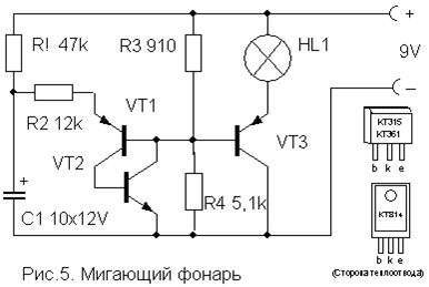
Transistors VT1, VT2 - any low-power of the corresponding structure (KT312, KT315, KT342, KT 503 (n-p-n) and KT361, KT645, KT502 (p-n-p), and VT3 - medium or high power (KT814, KT816, KT818).
A simple device for listening to the soundtrack of TV programs on headphones. Does not require any power supply and allows you to move freely within the room.

Coil L1 is a "loop" of 5 ... 6 turns of wire PEV (PEL) -0.3 ... 0.5 mm, laid along the perimeter of the room. It is connected in parallel to the TV speaker through the SA1 switch as shown in the figure. For normal operation of the device, the output power of the TV audio channel should be within 2… 4 W, and the loop resistance should be 4… 8 Ohm. The wire can be laid under the skirting board or in a cable duct, and it should be placed, if possible, no closer than 50 cm from the 220 V mains wires to reduce alternating voltage pickups.

The L2 reel is wound on a frame made of thick cardboard or plastic in the form of a ring 15 ... 18 cm in diameter, which serves as a headband. It contains 500 ... 800 turns of wire PEV (PEL) 0.1 ... 0.15 mm fixed with glue or electrical tape. A miniature volume control R and an earphone (high-impedance, for example TON-2) are connected in series to the terminals of the coil.
Light switch off
This one differs from many schemes of similar automata in its extreme simplicity and reliability and does not need a detailed description. It allows you to turn on the lighting or any electrical appliance for a specified short time, and then automatically turns it off.

To turn on the load, it is enough to briefly press the SA1 switch without latching. In this case, the capacitor has time to charge and opens the transistor, which controls the switching on of the relay. The turn-on time is determined by the capacitance of the capacitor C and with the rating indicated in the diagram (4700 mF) is about 4 minutes. An increase in the on time is achieved by connecting additional capacitors in parallel with C.
The transistor can be any n-p-n type of medium power or even low-power, such as KT315. It depends on the operating current of the relay used, which can also be any other for a response voltage of 6-12 V and capable of switching the load of the power you need. You can also use p-n-p type transistors, but you will need to change the polarity of the supply voltage and the switching on of the capacitor C. Resistor R also affects the response time within small limits and can be 15 ... 47 kOhm, depending on the type of transistor.
List of radioelements
| Designation | A type | Denomination | amount | Note | Score | My notebook | |
|---|---|---|---|---|---|---|---|
| Electronic duck | |||||||
| VT1, VT2 | Bipolar transistor | KT361B | 2 | MP39-MP42, KT209, KT502, KT814 | Into notepad | ||
| HL1, HL2 | Light-emitting diode | AL307B | 2 | Into notepad | |||
| C1 | 100μF 10V | 1 | Into notepad | ||||
| C2 | Capacitor | 0.1 uF | 1 | Into notepad | |||
| R1, R2 | Resistor | 100 kΩ | 2 | Into notepad | |||
| R3 | Resistor | 620 Ohm | 1 | Into notepad | |||
| BF1 | Acoustic emitter | TM2 | 1 | Into notepad | |||
| SA1 | Reed switch | 1 | Into notepad | ||||
| GB1 | Battery | 4.5-9V | 1 | Into notepad | |||
| Bouncing metal ball sound simulator | |||||||
| Bipolar transistor | KT361B | 1 | Into notepad | ||||
| Bipolar transistor | KT315B | 1 | Into notepad | ||||
| C1 | Electrolytic capacitor | 100uF 12V | 1 | Into notepad | |||
| C2 | Capacitor | 0.22 μF | 1 | Into notepad | |||
| Dynamic head | DG 0.5 ... 1W 8 Ohm | 1 | Into notepad | ||||
| GB1 | Battery | 9 Volts | 1 | Into notepad | |||
| Engine Sound Simulator | |||||||
| Bipolar transistor | KT315B | 1 | Into notepad | ||||
| Bipolar transistor | KT361B | 1 | Into notepad | ||||
| C1 | Electrolytic capacitor | 15μF 6V | 1 | Into notepad | |||
| R1 | Variable resistor | 470 k Ohm | 1 | Into notepad | |||
| R2 | Resistor | 24 kΩ | 1 | Into notepad | |||
| T1 | Transformer | 1 | From any small-sized radio | Into notepad | |||
| Universal Sound Simulator | |||||||
| DD1 | Chip | K176LA7 | 1 | K561LA7, 564LA7 | Into notepad | ||
| Bipolar transistor | KT3107K | 1 | KT3107L, KT361G | Into notepad | |||
| C1 | Capacitor | 1 μF | 1 | Into notepad | |||
| C2 | Capacitor | 1000 pF | 1 | Into notepad | |||
| R1-R3 | Resistor | 330 k Ohm | 1 | Into notepad | |||
| R4 | Resistor | 10 kΩ | 1 | Into notepad | |||
| Dynamic head | DG 0.1 ... 0.5W 8 Ohm | 1 | Into notepad | ||||
| GB1 | Battery | 4.5-9V | 1 | Into notepad | |||
| Flashlight | |||||||
| VT1, VT2 | Bipolar transistor | ||||||
Every day it becomes more and more, there are many new articles, it is quite difficult for new visitors to immediately navigate and revise everything already written and previously posted at a time.
I would very much like to draw the attention of all visitors to individual articles that were posted on the site earlier. In order not to have to search for the necessary information for a long time, I will make several "entrance pages" with links to the most interesting and useful articles on specific topics.
Let's call the first such page "Useful electronic homemade products". Simple electronic circuits that are available for implementation by people of all skill levels are considered here. The circuits are built using a modern electronic base.
All information in the articles is presented in a very accessible form and in the amount necessary for practical work. Naturally, to implement such schemes, you need to understand at least the basics of electronics.
So, a selection of the most interesting articles on the site by topic "Useful electronic homemade products"... The author of the articles is Boris Aladyshkin.
The modern element base of electronics greatly simplifies the circuitry. Even a regular twilight switch can now be assembled from just three parts.
The article describes a simple and reliable electric pump control scheme. Despite the extreme simplicity of the circuit, the device can operate in two modes: water rise and drainage.
The article contains several schemes of devices for spot welding.
With the help of the described structure, it is possible to determine whether or not a mechanism located in another room or building is working. The vibration of the mechanism itself is information about the work.
A story about what a safety transformer is, what it is for and how you can make it yourself.
Description of a simple device that disconnects the load if the mains voltage goes out of range.
The article describes a circuit of a simple thermostat using an adjustable zener diode TL431.
An article on how to make a device for smoothly switching on lamps using the KR1182PM1 microcircuit.
Sometimes, with low voltage in the network or soldering of massive parts, it becomes simply impossible to use a soldering iron. This is where a step-up power regulator for a soldering iron can come to the rescue.
An article about how you can replace the mechanical thermostat of an oil heating radiator.
Description of a simple and reliable thermostat circuit for a heating system.
The article provides a description of the converter circuit made on a modern element base, containing a minimum number of parts and allowing to obtain significant power in the load.
An article about various ways to connect a load to a control unit on microcircuits using relays and thyristors.
Description of a simple control circuit for LED garlands.
The design of a simple timer that allows the load to be turned on and off at specified intervals. Working time and pause time do not depend on each other.
Description of the circuit and principle of operation of a simple emergency luminaire based on an energy-saving lamp.
A detailed story about the popular "laser-ironing" technology for manufacturing printed circuit boards, its features and nuances.
One of the common hobbies of hobbyists and electronics professionals is the design and manufacture of various homemade products for the home. Electronic homemade products do not require large material and financial costs and can be performed at home, since work with electronics is, for the most part, "clean". The only exception is the manufacture of various body parts and other mechanical assemblies.
Useful electronic homemade products can be used in all areas of everyday life, from the kitchen to the garage, where many are engaged in the improvement and repair of electronic devices in a car.
Homemade products in the kitchen
Electronic homemade kitchens can be added to existing accessories and supplies. Industrial and home-made electric BBQ grills are very popular among apartment residents.

Another common example of homemade kitchens made by a home electrician is timers and automatic lighting over work surfaces, electric ignition of gas burners.
Important! Changes in the design of some household appliances, especially gas appliances, can cause "misunderstanding and rejection" of regulatory organizations. In addition, it requires great care and attention.
Electronics in the car
Home-made devices for a car are most widespread among the owners of domestic brands of transport, which differ in the minimum number of additional functions. The following schemes are in great demand:
- Sound indicators of turns and hand brake;
- Indicator of operating modes of the storage battery and generator.

More experienced radio amateurs are engaged in equipping their car with parking sensors, electronic window drives, automatic light sensors to control low beam headlights.
Homemade products for beginners
Most novice radio amateurs are engaged in the manufacture of structures that do not require high qualifications. Simple proven designs can serve for a long time and not only for the sake of benefit, but also as a reminder of the technical "maturation" from a novice radio amateur to a professional.
For inexperienced hobbyists, many manufacturers produce ready-made design kits that contain a printed circuit board and a set of elements. Such kits allow you to practice the following skills:
- Reading circuit and wiring diagrams;
- Correct soldering;
- Adjustment and adjustment according to the ready-made method.
Among the sets, electronic clocks of various designs and degrees of complexity are very common.

As an area of \u200b\u200bapplication of knowledge and experience, radio amateurs can design electronic toys using simpler circuits or reworking industrial structures to their wishes and capabilities.
Interesting ideas for crafts can be seen on examples of making radio electronic crafts from worn-out parts of computer technology.
Home workshop
For the independent design of radio electronic devices, a certain minimum of tools, fixtures and measuring devices is required:
- Soldering iron;
- Side cutters;
- Tweezers;
- Screwdriwer set;
- Pliers;
- Multifunctional tester (avometer).
On a note. When planning to do electronics with your own hands, you should not tackle complex structures right away and purchase an expensive tool.
Most radio amateurs began their journey with the use of the simplest 220V 25-40W soldering iron, and the most popular Soviet tester Ts-20 was used from the measuring instruments in the home laboratory. All this is enough for practicing with electricity, acquiring the necessary skills and experience.

It makes no sense for a novice radio amateur to buy an expensive soldering station if there is no necessary experience with a conventional soldering iron. Moreover, the possibility of using the station will not appear soon, but only after sometimes quite a long time.
Also, there is no need for professional measuring equipment. The only serious instrument that even a novice hobbyist may need is an oscilloscope. For those already versed in electronics, the oscilloscope is one of the most sought after measurement tools.

Inexpensive Chinese-made digital devices can be successfully used as an avometer. Having rich functionality, they have high measurement accuracy, ease of use and, what is important, have a built-in module for measuring transistor parameters.
Speaking of a homemade workshop at a homemade product, one cannot fail to mention the materials used for soldering. This is solder and flux. The most common solder is the POS-60 alloy, which has a low melting point and ensures high soldering reliability. Most of the solders used for soldering various devices are analogs of the mentioned alloy and can be successfully replaced by it.
As a flux for soldering, ordinary rosin is used, but for ease of use it is better to use its solution in ethyl alcohol. Rosin-based fluxes do not need to be removed from the installation after work, since they are chemically neutral under most operating conditions, and a thin rosin film formed after the evaporation of the solvent (alcohol) exhibits good protective properties.
Important! When soldering electronic components, under no circumstances should active fluxes be used. This is especially true of soldering acid (zinc chloride solution), since even under normal conditions such a flux has a destructive effect on thin copper printed conductors.
To service highly oxidized leads, it is better to use an active acid-free flux LTI-120, which does not require rinsing.
It is very convenient to work using solder, which includes a flux. The solder is made in the form of a thin tube with rosin inside.

Breadboards made of double-sided foil-clad fiberglass, which are produced in a wide range, are well suited for the installation of elements.

Security measures
Electricity is associated with a risk to health and even life, especially if do-it-yourself electronics are designed with mains power. Homemade electrical devices should not use transformerless AC mains power. In an extreme case, the adjustment of such devices should be done by connecting them to the network through an isolation transformer with a transformation ratio equal to one. The voltage at its output will correspond to the mains, but at the same time, reliable galvanic isolation will be provided.