Homemade vacuum cleaner brushes. Vacuum cleaner attachments for cleaning fluffy materials
Chances are, your vacuum cleaner was already sold with one or more optional attachments. It is possible that there was an instruction with a detailed description, but the problem is that the vast majority of buyers do not read the instructions.
FOR HIGH OBJECTS AND CEILINGS
This is a hose extension tube, and its purpose is quite clear. It can be used in conjunction with an additional attachment that is attached to the end of the pipe. It is needed in order to get to hard-to-reach high places. For example, up to ceiling skirting boards, the top surface of the refrigerator or kitchen cabinets, and with the help of an additional pipe, it is convenient to remove dust behind furniture. You can choose a longer and shorter pipe depending on the height of your ceilings.
FOR UPHOLSTERED FURNITURE, MATTRESSES AND CUSHIONS
To prevent dust from spoiling the furniture and making it dull and gray, do not forget about the nozzle for cleaning upholstered furniture. Do not look at the fact that she is so small and inconspicuous. It's great for pulling dust out of cushions, roman blinds and even mattresses.
FOR FLOOR FLOORS
This flat wide brush is best for flat floors. Its short bristles perfectly grip dirt, crumbs and hair, which are then sucked into the vacuum cleaner. Typically, these brushes are equipped with wheels or a rotating head, which makes them manoeuvrable and easy to use.
FOR ABAJURS, BOOKS AND HOUSEHOLD APPLIANCES

The brush attachment is usually round or triangular in shape with long soft bristles that will not scratch the surface. It can remove dust from furniture, clean lampshades, blinds, curtain rods, household appliances and books.
FOR SLITS AND CORNERS
This one of the most familiar - the narrow crevice nozzle for hard-to-reach places that cannot be reached with a regular brush. It is convenient for her to vacuum along the baseboard and between the vents, as well as in other narrow corners. For example, the crevice tool is useful for sofas and armchairs to remove dust between pillows.
TO REMOVE WOOL
This attachment will be appreciated by pet owners. The rubber bristle brush creates a static charge and lifts the hairs up and makes them easier to absorb. Therefore, cleaning is faster and better.
FOR CARPETS AND CARPETS
The turbo brush is ideal when you need to add power. With this nozzle, you can thoroughly brush your carpet and effectively remove dirt from the pile.

The material of the previous article talks about the consequences that can arise as a result of cleaning construction dust and debris with an ordinary household vacuum cleaner, even of such a brand name as Samsung.

Here we should focus on the fact that a rotor rotates inside the housing with a stator winding, fixed on the shaft axis with two bearings.

It contains:
- magnetic core;
- a winding connected to a manifold assembly with plates.
An electrical contact for the passage of current through the armature winding is created by brushes pressed against the plates by the force of a compressed spring.
The fan impeller always rotates in one direction. Therefore, for its fastening, a threaded nut is used, which is screwed in the opposite direction to rotation. When the vacuum cleaner is operating, it is additionally fixed by the forces of inertia, but cannot be unscrewed.
The same principle is used with bicycle pedals: they have two types of different thread directions applied: right and left winding for their side.
Disassembly sequence
To repair the electric motor of the vacuum cleaner, you must initially:
- remove the brushes from the body;
- unscrew the fixing nut with a left-hand thread so as not to damage the windings on the stator and rotor and to preserve the design of the collector mechanism, to leave it in good condition;
- remove the armature and assess the condition of the bearings, conductors and windings.
All these steps I had to perform in order to disassemble the electric motor of the Samsung vacuum cleaner. I show them with photos.
Removing the brushes
Install the screwdriver one by one on the fastening screw and turn it out.

We carefully remove the brush with our hand and examine it.

Traces of carbon deposits with the formation of layers of graphite dust are visible to the naked eye.

The same picture is observed on the second brush. Traces of sparking are clearly visible on the end surface.

This allows us to conclude that an external inspection of the collector and an electrical check of the condition of the rotor and stator windings are necessary.

It is impossible to do this through a closed engine casing: it needs to be disassembled and the anchor removed.
3 ways to unscrew the rotor nut
Let's call them conditionally according to the technology of work performance:
- slot-slot cutting;
- fixation with a loop on a stranglehold;
- fastening in a vice through adapters.
Each of these methods has its own advantages and disadvantages, it can be applied depending on the availability of equipment and tool base.
Shaft slot
A bit of history
This rotor attachment technology was used on the collector motor of any vacuum cleaner produced during the Soviet era. For the convenience of manual assembly and subsequent repair, a groove for a screwdriver blade was always created at the factory at the end of the shaft.
Its force fixed the position of the rotor shaft, and the torque from the wrench clamped or loosened the nut. I still have a similar engine that was used in. This slot can be clearly seen in the photo below.

Modern technologies
Nowadays, production widely uses industrial robots and automation of all processes. In addition, the marketing policy of well-known manufacturers is designed for:
- long service life of the manufactured equipment within the declared resource;
- performing repairs by block-by-block replacement of failed devices without disassembling them.
For these reasons, a defective collector motor is simply replaced by the manufacturer for a new one without disassembling it: this is faster, easier and more profitable. Well, our home master loves to fix everything with his own hands in the old fashioned way.
How to make a slit
The vacuum cleaner motor mounting nut and rotor shaft are made of ordinary steel. You can make a cut in them. However, in our case, it is not possible to perform it in the usual way by deepening the fan casing, in which they are hidden. Therefore, you will have to use an ordinary and circular saw of the appropriate diameter at its end.

Then we put the key on the nut, and a screwdriver on the cut in the engine shaft. It remains to apply force to create the opposite torque and use it to disassemble the mount.

I did not use this technology: there was no small circular saw at hand for cutting metal. I tried two other techniques in my work.
And you can watch its implementation in the video by Alexander M “How to Unscrew the Nut”.
Loop
The method is based on holding the armature for the collector plates using a stranglehold assembly. I had to check two options for unscrewing the nut using:
- soft copper wire:
- plastic rope.
Fastening with wire
In principle, PVC insulation of the installation wire squeezes the rotor shaft well along the collector plates, maintaining the integrity of their surface, and allows you to hold it to unscrew the nut.

I used a copper wire with a diameter of 2.5 mm square. However, the loop design turned out to be weakly tightened and did not completely provide the noose. When working with a wrench, I felt that the shaft was spinning and did not apply much force.
When I pulled my wire out of the engine, I saw frayed insulation on it. I did not experiment with this method any more. However, I suggest looking at this technology in the HamRadio video “How to Unscrew the Nut on the Engine”.
Cord fastening
He took a piece of thin rope and folded it in half along its length. In the middle, I passed a soft wire that acts as a needle.

With its help, it turned out to be convenient to put the soft cord in a loop on a noose and pass it around the collector plates.

Tied a fastener knot around the case window.

An attempt to unscrew the nut in this way did not work for me: the structure of the cord turned out to be weak - it simply broke from the applied tensile forces.
If you repeat this method, then choose a stronger rope, cord or belt.
Clamp in vise
To fix the anchor in this way, it was required to make two adapters from wood in the form of rectangular blocks.

Their cross-section should go into the hole of the housing for attaching the brush, and the length should reach the collector plates and protrude slightly outward. These distances are better than a preliminary or ruler.
Moreover, the side adjacent to the rotor must be filed with a round file in the form of a segment for a snug fit to the motor shaft.

With the help of these adapters, it was possible to fix the engine rotor in a vice, pressing it with medium force.

It remains to set the socket wrench to 12 mm and rotate it clockwise.

The nut is safely unscrewed. A machined factory cavity is visible on its inner surface.

Further disassembly
Removing the upper engine mount cover
It is simply put on top and crimped around the perimeter in four places.

Factory-created dents can be carefully leveled with pliers.

The cover is then simply lifted off by hand and removed from the motor housing.

Air pump wheel
There is a fan under the cover. It shows a slight damage to the plastic part of the case.

Inside the cover, layers of dust remaining after the engine has been purged are clearly visible. They can also be seen in the photo of the fan near the inlet blades.

It stuck to and under the washer.

We unscrew the fastening screws with a screwdriver.

Disassembling the anchor
Fastening is carried out:
- screws through the upper tab with a compartment for the upper bearing race;
- protrusions with grooves in the lid;
- the lower bearing race.
Rotor fixing screws in the motor stator
We can access them immediately after removing the plastic fan casing.

We promote them. In parallel, we pay attention to the amount of construction dust inside the case, which remains even after it has been blown out from the outside.

Retaining plate protrusions that fit into the grooves of the stator housing
They are located next to the fastening screws and provide additional fastening to the rotor.

Carefully guide them with a flat screwdriver to the exit from the grooves.

Then we hold the mounting plate with our fingers through the internal holes or hang it on a support. The rotor is still supported by attaching the outer race of the lower bearing. By the way, it turned out to be additionally glued to me.
The protruding threaded end of the shaft shaft must be protected from damage with a piece of dry hardwood board and hit with a hammer. The rotor will be knocked out of the stator.

Visual inspection
Traces of carbon deposits from the graphite dust formed as a result of burning brushes and glue on the bearing cage are clearly visible on the rotor.

I tried to remove the contamination of the plates in the traditional neat way: wash it off with alcohol or its solution using a cotton swab.

Carbon deposits have become attached to the metal quite strongly, dissolving very poorly. I had to work as a steel raven. The photo below shows a preliminary cleaning result that requires additional surface polishing.

But, for electrical measurements, this is quite enough. Then, the grooves between the collector plates are cleaned from debris, dust and carbon deposits that can shunt the rotor winding chains. At first he worked as a raven, and then as a scraper made of non-coniferous wood.

Electrical checks of armature circuits
I took my old tester and. It turned out to be with a very large spread from one to 13 ohms in four adjacent areas.

This is clear evidence that wire breaks have been created between the windings and electrical circuits are broken. The wiring diagram of a serviceable rotor in a simplified form is as follows.

The collector plates are isolated from each other, but connected in series in a circle with exactly the same sections of windings made of equal lengths of wire with the same electrical resistance R1. They are collected in a single electrical circuit and therefore show equal values with a working engine. Taking into account measurement errors and installation technology, their value can differ only by a fraction of Ohm and not more.
If the deviations are higher, then this indicates the breakage of individual conductors, creating a parallel chain through an air gap with a huge electrical resistance. Which is what I did.
I begin to look for a breakage point on the winding: I examine the anchor and notice places of blackening of the wire and dangling ends.

I show these areas larger with small comments.

The conclusion suggests itself: such a winding cannot be exploited. It must be replaced with a serviceable one.
This malfunction was indirectly indicated by:
- burnt surfaces of rubbing brushes;
- Burnt graphite dust on manifold plates.
The rotor winding can be rewound by hand. This is a very real job for a home craftsman and I had to do it when repairing the anchor of a Soviet Raketa vacuum cleaner.
- you will have to mark the collector plates with an indelible marker;
- on the basis of the created markup, reproduce on paper the entire wiring diagram between the grooves of the magnetic circuit. To do this, you will have to literally feel them with your hands and carefully look out for them with your eyes;
- completely carefully remove the old wires without damaging the electrical insulation of the core;
- find a new copper wire of the same cross-section with an insulating layer of varnish that is resistant to high temperatures. A thin conductor will not withstand current loads, and the turns of a thicker one simply will not fit in the grooves of the magnetic circuit;
- laying in grooves requires increased care and constant fixation of the installation results on paper;
- there will be difficulties with the electrical connection of the laid wires in the grooves of the collector plate. The usual one may not provide the temperature regime. Refractory solders must be used.
It took me a little more than two weeks to rewind the armature winding with my own hands in an electrical laboratory. I did it during lunch breaks and in the windows between the main tasks. Then I fixed the engine, but I do not advise doing this work on my own.
The cost of an electric motor is about half the price of a vacuum cleaner. Therefore, consider what is more profitable:
- replace the burnt out rotor or stator with rewound ones;
- buy the entire engine and install it in the old case;
- or just purchase a new brand of vacuum cleaner with a warranty period of service.
Advice for the future: it is cheaper to remove building dust after renovating an apartment with a slightly damp cloth than with a household vacuum cleaner not designed for this purpose.
We hope that the video oleg pl “How to disassemble a vacuum cleaner motor” will help you.
Chances are, your vacuum cleaner was already sold with one or more optional attachments. It is possible that there was an instruction with a detailed description, but the problem is that the vast majority of buyers do not read the instructions. We understand this perfectly, and decided to tell you how to use the most common attachments correctly. By the way, if you like a special one, you can always buy an additional attachment. They are sold as special, for certain models, and universal, which are suitable for almost everyone. Cost depending on the type of nozzle from 800-1700 rubles.
For tall objects and ceilings

This is a hose extension tube, and its purpose is quite clear. It can be used in conjunction with an additional attachment that is attached to the end of the pipe. It is needed in order to get to hard-to-reach high places. For example, to the ceiling skirting boards, the top surface of the refrigerator or kitchen cabinets, and with the help of an additional pipe, it is convenient to remove dust behind furniture. You can choose a longer and shorter pipe depending on the height of your ceilings.
For upholstered furniture, mattresses and pillows

To prevent dust from spoiling the furniture and making it dull and gray, do not forget about the nozzle for cleaning upholstered furniture. Do not look at the fact that she is so small and inconspicuous. It's great for pulling dust out of cushions, roman blinds and even mattresses.
For even floors

This flat wide brush is best for flat floors. Its short bristles perfectly grip dirt, crumbs and hair, which are then sucked into the vacuum cleaner. Typically, these brushes are equipped with wheels or a rotating head, which makes them manoeuvrable and easy to use.
For lampshades, books and household appliances

The brush attachment is usually round or triangular in shape with long soft bristles that will not scratch the surface. It can remove dust from furniture, clean lampshades, blinds, curtain rods, household appliances and books.
For crevices and corners

This one of the most familiar is the narrow crevice nozzle for hard-to-reach places that cannot be reached with a regular brush. It is convenient for her to vacuum along the baseboard and between the vents, as well as in other narrow corners. For example, the crevice tool is useful for sofas and armchairs to remove dust between pillows.
To remove hair

This attachment will be appreciated by pet owners. The rubber bristle brush creates a static charge and lifts the hairs up and makes them easier to absorb. Therefore, cleaning is faster and better.
For carpets and carpets

The turbo brush is ideal when you need to add power. With this nozzle, you can thoroughly brush your carpet and effectively remove dirt from the pile.
This article is about how I assemble my robot vacuum cleaner. There are many photos and videos for those who are also fond of such an idea.
December 19, 2014. I started to get interested in robotic vacuum cleaners five years ago in 2009, probably after getting to know Roboforum. All these years there were attempts to start something, but nothing was done. A couple of months ago I was actively reading articles about a robot vacuum cleaner and finally decided that I would buy a Karcher RC 4.000. As time passed, my wife often began to clean the kitchen and the corridor, it began to annoy me, the thought of a robot grew stronger and stronger. I again spent a couple of evenings in pictures and forums about robotic vacuum cleaners. Finally I decided that I would make a robot myself!
The goal is to create a robot vacuum cleaner no worse than an industrially manufactured one and get rid of a layer of dust and small debris in the house. In the process of studying the device of robots, it turned out that they are very noisy, about 60 dB, while a stationary home washing vacuum cleaner makes about 80 dB. My homemade robot should work as quietly as possible, its dimensions should not exceed the dimensions of factory robots, and it should clean quickly and efficiently.
The first step was to resolve the issue with the suction turbine. I already had experience building turbines, but they all worked poorly. For the garage, I made a homemade vacuum cleaner from a turbine from an old Raketa vacuum cleaner. The robot needs a small turbine, so I started looking over again. Quite by accident, I found messages from the user Vovan on the Roboforum, he shared a drawing of his turbine. Without thinking for a long time, I redrawn the drawing and glued my turbine.
I cut out the turbine and glued it from thick cardboard using super glue in 20 minutes. The first tests were successful!


December 20, 2014. I bought a body peeling today :) in general, I only need a transparent jar with a screw cap, I gave the contents to my wife. I also bought a brush for clothes with a hard bristle, took it apart, tomorrow I will make a brush out of it for my robot.

In AutoCAD, I made sketches of the location of the elements in the body. I stopped at the size of a basin with a diameter of 25 cm and a height of about 9 cm. It is not yet clear whether all the elements will fit in, there is really little space, but I don't want to make a body anymore. I set a framework for myself :)
Yesterday on the Internet I wrote out the sizes of factory robotic vacuum cleaners:
diameter * height (cm)
36 * 9
32 * 8
32 * 10
30 * 5
22 * 8
I decided to make my own vacuum cleaner with a cyclone filter, so you can't make the height small, it is determined by a can for collecting garbage, but you can win in diameter. For the cyclone, of course, thanks to Dyson, I have been reviewing his inventions for a long time and even made a garage vacuum cleaner according to the principle of a cyclone. My filter will be simple, without any cones and crazy suction power, for the first time it will come off.
December 21, 2014. I sawed off 15 cm of a round handle from a floor brush in the garage and made a round brush out of it. The diameter turned out to be about 70 mm. The size is unrealistically large and very stiff bristles, I don't know how it will behave, but you probably have to either alter or make the vacuum cleaner heavier, because the bristles will throw it up. I simply inserted the bristles into the holes without glue, it turned out reliably. The whole structure was fixed on a hairpin with a diameter of 6 mm and two bearings at the edges.
Found two wheels in the garage, you won't believe it, from a vacuum cleaner! The same handheld vacuum cleaner in which there was nothing electric, only 4 wheels and two brushes driven by these wheels. The wheels have been waiting in the wings for about 15 years :)

Now in AutoCAD I will make another drawing for several parts, tomorrow I will cut everything out of plywood and try to assemble something based on it.
December 22, 2014. I really want to make a robot vacuum cleaner with my own hands and finish it before the new year 2015. Last night on YouTube I watched again several videos about robotic vacuum cleaners and, in particular, two videos about Dyson 360 Eye and Fluffy:
After the first video with the Dyson robot, I realized that by making my robot with a diameter of 25 cm and a brush 15 cm long, I would leave dirty places along the baseboard 5 cm wide. After the second video, the brain completely rebooted and thought about making a brush in front of the robot ?! I don’t know what I’ll do next, the tests will show.
So, today I bought a new scoop and two brushes with softer bristles. I bought the scoop because of the elastic that is glued along the edge, it will perfectly fit my design.

I slightly changed the geometry of the body based on new thoughts and a new brush. The robot is still 25 cm, but now it is half a circle and half a square. The width of the brush is 21 cm, the diameter is about 6 cm. I cut out the base from 8 mm plywood, attached the wheels and a brush, tomorrow I will make a gearbox and try to sweep something :)

December 23, 2014. I screwed a gear to the brush and attached a reducer next to it, used an elastic band for money as a belt, and screwed a motor for the test. Below in the video is a test at 6 and 9 volts.
Most likely I will redo the brush again, the pile is too short and too hard. The pile must be free of gaps, because streaks of dirt remain. In general, it turned out spectacular :)
I figured if I had enough space for three motors in the case. Two motors will drive two wheels and one brush. Plus, gearboxes will take up a lot of space. The idea came to replace the gear reducers with a worm gear, maybe I'll do a couple of tests.

The suction turbine was coated twice with a layer of epoxy resin, it became like plastic. The cardboard no longer bends and if water gets in everything will be fine. I didn't have to center it, it turns perfectly. In the meantime, I am preparing the basis for the garbage can. I made a fine filter from the neck and lid of a kefir bottle. I took a disposable bag from a vacuum cleaner as a filter cloth. While everything is glued, in a couple of days I will screw it onto the base and test everything again.

During the work on the robot, the thought constantly comes to mind to acquire a 3D printer. With a 3D printer, it would be much easier to create the details I need and with high precision. When you drill plywood with a drill, the drill can lead or the tilt is not exactly 90 degrees, here you can only dream of high accuracy. In addition, the plywood parts are very bulky, everything would be neat on a 3D printer.
December 24, 2014. In the morning I tested the turbine and the garbage can, in the afternoon I repeated the experiment with a higher voltage. The results are not impressive. The fine filter had to be unscrewed for now, because through it the power drops dramatically. In the jar, the garbage spins very effectively, but in reality, the suction power is not enough.
High voltage turbine test.
At these moments, there was a desire to score at everything, why did I even undertake this. Nowadays it is very easy to drop everything and forget - it’s the easiest way.
In the evening I took a brushless motor and began to glue a new turbine for it according to the same drawings.
December 25, 2014. I finished the second turbine for a brushless motor, I wanted to test it, it turned out that the motor was rotating in the wrong direction. Tomorrow I'll go to the garage to re-solder the wires, but for now I put everything aside.
December 26, 2014. I re-soldered the wires between the controller and the motor, got the rotation in the right direction. The turbine started to work, but a couple of knee tests turned out to be sad again. Maybe I will even redo the design of the turbine, adding a little taper, but more on that later.

The last two days I have devoted very little time to development, I will try to allocate 4-5 hours tomorrow.
December 27, 2014. I decided to try to assemble a worm gear for the chassis of the robot vacuum cleaner. In the pictures earlier, I showed that you can make a worm from a nail and a piece of copper wire. The problem turned up in the process of soldering the wire to the nail. My soldering iron is not very powerful, so I additionally heated the nail on a gas burner. However, it did not work out to solder the wire with high quality, so I took a round piece of wood and wound the wire around it, spilled the turns with super-glue. The worm turned out to be quite tolerable. Ignoring the ovality of the wooden base and, in general, the entire plywood block, the mechanism worked fine, but damn it very slowly.


It would be nice to get ready-made plastic worm gears, but for now let's put this aside.
Regarding the future energy consumption of my robot. Now there is a snag with the turbine, something she does not want to suck as expected, even with the fine filter removed. If you use a conventional collector motor for a turbine and supply it with a voltage of 12 volts, then it will consume about 0.6 amperes. If you use a brushless motor, then it will consume about one ampere. Plus, two collector motors will be used to move the robot and one more for the brush, each will consume about 0.3 amperes. Electronics will also consume something. In total, the robot will "eat" about 1.6 to 2 amperes, in peaks probably up to 2.5 amperes. I don't know a lot or not, it seems like industrial robots consume three or more amperes.
Again I reviewed a bunch of videos and photos on the request "the principle of the robot vacuum cleaner". Found a cool photo of a turbine from an ordinary household vacuum cleaner. I read on some forum that the longer the turbine blades, the more vacuum it can create due to centrifugal force.

December 28, 2014. Today I glued two more turbines, they differ only in thickness. Made the blades as long as possible. In the photo below, the first thin (5mm blade height) turbine, it is very quiet in operation, but it doesn’t suck :)

The second turbine is thicker (15mm blade height).

Once again in the garage I tried to drag the brush across the floor, the motor often shuts up from the load, the bristles still turned out to be very stiff, and the diameter of the brush would not hurt to reduce. Tomorrow, in any weather, I am going to buy a brush with the softest bristles, I will also go to a toy store to look for cars with a worm gear for the robot's chassis.
In the garage I tested a new turbine with a voltage of 12 volts, I thought that 9 blades might not be enough. At home, I glued the third turbine in a day with long blades and an amount of 15 pieces, I attach a photo:

Another day is over. Until the new year, I won't have time to make a vacuum cleaner as planned, but I want to believe that everything will be fine :)
December 29, 2014. Went to a toy store today looking for a worm gear. On the way I remembered about my daughter's toy - a horse. This horse of my daughter didn't really like it, and in general, I don't really like it either :) But on the other hand, it has two worms and 4 + 4 gears inside it.


I still looked into the toy store, then into the second one and bought a shape-shifting machine there. I bought a car not so much for the mechanism as for its wheels, they climb any surface. There was no worm gear inside the machine. It is quite possible that I use the wheels for a home-made robot, but for now I gave the car to my daughter - she is delighted :)


In the afternoon, the idea came to my mind to make a robot electric broom, i.e. the design is the same as now, only there is no turbine, the debris is simply collected in the compartment. When I was looking for a new brush with a softer bristle in the store (I never bought it), I accidentally saw this:

Of course, I bought this cover right away. This is a ready-made body of the robot, transparent according to the modern one, and there are not even unnecessary elements. But in fact it is a "Microwave Oven Lid" (diameter 24.5 cm), what to cover and why I don’t know, but the robot should turn out beautiful :) But more about that in another article.
In the evening I broke the bunk, took out the gears and screwed them to my robot, it turned out great! The mechanism takes up a minimum of space and is strong enough to move the platform. So far I have not collected everything, so the pictures will be later. In the meantime, I am hatching the idea of how to make a new brush, reduce its diameter to 3-4 cm and replace the gearbox with gears with a worm gear.
By the way, on a note, the worm can be removed from other toys. So we had a broken elephant lying around, but in principle it doesn't matter, the main thing is the mechanism, which is the same in many toys (cars, tanks and others), see the pictures:


Oh yes, I forgot to write about the new turbine, it turned out to be noticeably more productive than all the others. For better air flow, I also added a cone in the middle of the turbine.
January 05, 2015. Despite the New Year holidays, all the previous days I tried to somehow get ahead in my work. I re-read a lot of information about 3D printers, if there was such a printer in my arsenal, I would have printed most of the parts long ago. While in my head I'm making plans for the future how to assemble a 3D printer with my own hands.
Today I have made a new brush. I took a wooden stick with a diameter of 10 mm and drilled holes in a spiral. I inserted bristles into the holes and sealed them from the back with a wood burner.

I assembled the undercarriage, until I tested it, the glue dries. I also put the new brush in place, it turned out a lot of jambs, without them in any way, after all, this is my first robot. By the way, I abandoned the rectangular back and made the base for the round body. My decision is connected with rethinking the movement of the robot, if we imagine that the robot is moving along the wall and rests against something, then in order to turn it will have to make a maneuver with movement back, because the square ass will be brought onto the wall.

I spent a lot of time looking for a solution for the "vision" of the robot. The mechanical bumper does not suit me very much, it spoils the external one, although it is the simplest scheme for determining obstacles. I settled on an infrared sensor. It is not yet possible to assemble the sensor due to the lack of infrared phototransistors.
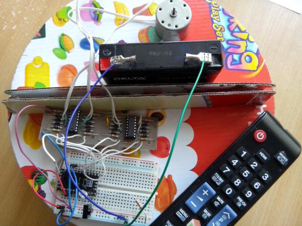
January 07, 2015. Yesterday until 1 am I was assembling the robot in order to somehow test it, play around :) The Arduino Pro Mini + motorschild board on L293E microcircuits with a harness is used as a "brain" (I used this board in my first project to control motors online via the Internet). Control is carried out from the remote control from the TV. Short video:
The design looks liquid, in fact it is, almost all mechanisms are barely breathing. Today I realized how much a seemingly simple robot is so difficult to make. At the moment, I have problems in almost all nodes, a global rework of almost everything is required.
The wheel drive on a worm gear turned out to be just right in terms of speed, but its performance leaves much to be desired. Part of the drive is located in a compartment where air with debris will flow, this will not work for a long time. On the wheels, I wanted to drill holes that would serve as an additional motion sensor. An IR LED will be located on one side of the wheel, and an IR phototransistor on the other. When the robot moves, this circuit will pulsate, if there are no impulses, then the robot is resting on something and does not move.
For proximity sensors, I bought IR LEDs and IR phototransistors, but after testing such an IR bumper, it became clear that the idea is not good. The sensor reacts to sunlight, but does not see black objects at all. The design has the right to life, but in simpler homemade products. Who is interested in the scheme I share:

If you bring your hand close to the sensor, the LED on the breadboard lights up.

Also I tried the ultrasonic sensor. It perfectly measures the distance, but only by the "head-on" method, if the plane of the object is at an angle, then the readings are distorted. In general, even with such a sensor, the bumper of the robot will not work normally.

For control from the remote control, a TSOP IR receiver was used, I don’t know what markings, in principle, you can use any that comes across. You can control it from any remote control, even from a mobile phone, but before that you need to find out the codes of the buttons you press on the remote control. The sketch shows a simple circuit that sends a button code to the port monitor when the remote control is pressed. Connection example and sketch below:

As for the sweeping brush, it turned out excellently, the width is almost 21 cm, with a body of 25 cm. There are nuances: the villi do not recover if they are crushed. The drive mechanism is not covered by anything, it will wind the hair in 3 minutes of work and stop it. The brush is not removable. The motor is very weak, but the number of revolutions is very suitable, it sweeps very effectively on the table.


Now this robot vacuum cleaner will be disassembled and rethought. Most likely, the diameter of the body will increase by 3 cm. Initially, I thought of making the wheels on an independent suspension, so that they would hide if suddenly someone steps on the robot. I will do the wheel drive on gears instead of a worm. The bristle for the brush needs to be looked for another, more elastic and to keep its shape. The bumper will probably have to be made mechanical. There are many questions about the suction turbine.
Despite all the shortcomings, the wife liked the robot, and the daughter is generally delighted :)
To be continued. I won't write about the robot so often, but I will try to publish photo and video reports at least once a month.
March 2015. I bought an electric broom.
The robot vacuum cleaner is still in the project!