Creating an airplane from ceiling tiles. Do-it-yourself aircraft models from ceiling tiles - video review and step-by-step instructions Styrofoam airframe drawing
Today's conversation is about flying foam models. The advantages of this material are obvious: the simplest model can be made in fifteen minutes, more complicated - in two or three hours.
Thin sheets of foam are the main building material for all the models of gliders and aircraft that we will talk about. Such plates can be cut from thick foam yourself using a nichrome wire heater, but the easiest way is to use ready-made cheapest foam ceiling plates, the so-called ceiling decor used in apartment renovations.
In addition to foam plates (ceiling decor), you will need wooden slats, preferably pine or linden, whatman paper, plasticine, and glue. A special glue is now sold for foam plastic.
The simplest of them is shown in Figure 1. Plan a wooden lath with a section of 4x4 mm. By the tail it can be made thinner - to reduce almost to nothing. Cut out the stabilizer and wing according to the dimensions shown in the figure. Round off the edges slightly with sandpaper. Heat the stabilizer consoles over the electric lamp and bend upwards at a right angle - you get two keels. Bend the wing consoles up by 20 degrees. Stick a piece of plasticine to the nose of the model so that the center of gravity of the model is approximately in the middle of the wing.
Before starting, check for wing and stabilizer warping.
Launch the model with a light push on the horizon. Do not be upset if the first flight is unsuccessful. The model needs to be taught to fly.
Suppose the glider dived sharply. Heat the rail with a soldering iron next to the stabilizer and slightly bend it up. If the glider is making a tight turn, fold back the trailing edges of the keels in the direction opposite to the direction of the turn.
If the model lifts its nose up, loses speed and falls on the wing, add some plasticine.
A well-adjusted model should fly more than ten meters when launched by hand.
You can make an interesting flying toy for your younger brother or sister. Look at picture 2. This duck is a great flier.
Cut out the body, wings and stabilizer from foam plastic plates. The configuration of the wings does not have to be strictly observed, it is only important not to reduce their area and not to break the symmetry of each pair.
The top wings should be parallel to the bottom wings when viewed from the side. And if you look from the front, the ends of the wings are about 10-15 mm higher than the root parts. In addition to glue, you can strengthen the wings with a pair of pins.
Glue a rounded plate to the bottom of the duck's beak, as shown in the figure. The angle of attack, that is, the slope of this plate, should be 8-10 degrees. On the front edge of the plate, attach 5-10 g of plasticine. Now run it and, if necessary, readjust as you would a glider.
Another simple model is the "frame" (Fig. 3). It is also built from rails and foam. Try to cut the slats as thin as possible. Stick a piece of plasticine to the nose, imitating the cabin.
Two keels of a large area significantly increase the directional stability of the model, so it flies almost straight or in a circle of large radius. The adjustment is the same.
Now let's move on to more complex models. True, they are not complex in themselves, but only in comparison with the first models.
But, before talking about them, let's say a few words about gluing foam.
The best adhesive is polyvinyl acetate emulsion (PVAE). It provides strength and elasticity, does not pollute the foam. For foam plastic, special glue is now sold at any specialized hardware store. Where they sell ceiling decor, they also sell this glue, for example, the Master glue. Stationery, casein, dextrin, BF-2, BF-4 - they all glue foam well.
What is the relative complexity of subsequent models? They are larger, therefore, the bearing planes must be made more rigid. It is unprofitable to increase the thickness of the wing: the model will become heavier, and in addition, drag will increase. So, we need to look for other ways. There are several.
First. Along the entire length of the wing and stabilizer, you need to cut a thin wooden lath from above. To do this, approximately in the middle of the wing, a groove is cut along the width of the lath, the lath itself is smeared with glue and inserted into the groove.
Second. Strips of drawing paper 10-20 mm wide are glued on top and bottom of the wing and stabilizer. Instead of drawing paper, you can use birch or lime veneer.
The third. The front and rear half of the wing are cut out separately and glued to the lath 1-1.5 mm thick. The width of the rail is equal to the thickness of the wing. This is perhaps the best way.
Figure 4 shows a schematic model of the airframe. You already know the manufacturing technology - here there are only other dimensions and stiffening of the wings and stabilizer. Such a model, if it is launched by a rail at a height of several tens of meters, will fly for about a minute and a half. And if you want it to fly even longer, give the wing and stabilizer an airfoil - it's shown in the picture.
The next model is in Figure 5. Its silhouette resembles modern aircraft. This glider can also be launched in the wind. The model is heavier than the previous ones, so you need to push harder when starting. It flies steadily and continuously.
The fuselage rail at the tail is two times thinner than in the bow - this is rational for strength and centering. The wing and tail are made of thicker foam plates compared to previous models. If the wing is not rigid enough, cut a pine or linden spar into it.
Give the wing and stabilizer an aerodynamic profile.
The glider shown in Figure 6 is launched from a rubber catapult like a slingshot. By bending the rear edges of the keel and stabilizer, it is possible to ensure that the model will perform a turn, a loop, and if the trailing edges of the wing consoles are bent in opposite directions, then a barrel.
And, finally, a very interesting model of the "flying wing" - in Figure 7. It is larger than some sports models. And the quality of its flight (provided that you carefully make it) will exceed all your expectations. The model reacts weakly to gusts of wind, moreover, it flies even better in the wind.
If it is not possible to make a wing from a whole plate, glue it from pieces. Glue the front edge with a pre-curved pine lath - for rigidity. The rail in the middle has a section of 3x3 mm, and to the ends 1.5x1.5 mm.
A stabilizer is installed in the center of the wing on two foam pylons. The angle of its installation is 5 - 8 degrees in relation to the root of the wing.
The weight is brought forward on a rail glued to the lower surface of the wing strictly in the center. Two keels are installed on the wing consoles.
A few "technological" tips. To cut the foam, use only a sharp knife, and do not put pressure on the knife, but kind of saw it with it. Then the foam will not crumble.
Sand the surface of the foam and along and across the wing. Small holes in the foam plastic have little effect on the quality of the flight, so there is no need to putty them. Do not press hard on the skin and do not move it quickly, because the foam can heat up and melt.
You can paint the model with colored ink from a spray bottle, applying a light layer. Do the following for the inscriptions on the wings: before painting, pin paper letters with pins, and after painting, remove them - you will get an unpainted inscription.
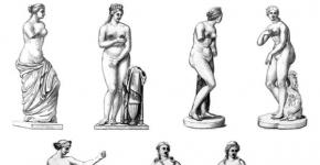
A small lightweight glider with a wingspan of 200 mm and a mass of 4 g (Fig. 1) belongs to the category of the simplest entertainment models and can be made in a few hours. It is launched in the gym from the hand or in calm weather on the sports ground using a catapult. A model with a wingspan of 230 mm and a mass of 7 g (Fig. 2) is somewhat heavier and stronger, its flight duration is higher (about 15 seconds).
The glider is designed to be launched from the hand and using a catapult (even with a slight wind) on a football or other field. A more complex model (Fig. 3) with a wingspan of 400 mm and a mass of 26 g is a throwable glider. Throwing gliders are built with enthusiasm by both beginners and experienced modellers. Competitions are held for this class of models. The main task is to achieve maximum flight duration. Height gain is provided only from a hand throw.
When designing such a glider, one has to solve a whole range of problems. It is necessary to achieve the optimal ratio of the mass of the model, the shape and area of \u200b\u200bthe bearing surfaces so that the glider can be thrown to the maximum height. After takeoff, the model should clearly enter the sustainable long-term gliding mode. To this end, in the proposed design, the nose of the fuselage is made quite short, and the tail boom is long, but light and strong. With such an aerodynamic configuration, the almost weightless and compact tail unit is located outside the zone of turbulence from the wing and works efficiently.
Even in the absence of updrafts, students of grades 5-6, with a correctly executed throw, managed to achieve a micro-vapor flight duration of up to 30 seconds. To run such a model, a field with dimensions of at least 200x200 meters is required, preferably outside the city. The preparatory work consists in making full-size drawings of parts, making templates for the wing, stabilizer, keel and forward fuselage, and selecting materials. You will need a ceiling foam tile 3.5 mm thick with dimensions of 500x500 mm (sold in building and finishing materials stores), dense foam grades, wood (spruce, pine, linden), PVA glue and paints.
Modeling is recommended to start with the manufacture of the wing, keel and stabilizer. These parts, after marking the contour according to the templates, can be cut out with a scalpel. Then you should start profiling them. In order to simplify the design, the wing has a flat-convex profile along the entire span. It is better to remove a significant part of the material from the line of maximum thickness with a sharp knife.
Finishing the surface is carried out with the help of sandpaper of various grain sizes, glued to plywood plates with dimensions of approximately 50x200 mm, with constant control according to the templates. To give the model wing (Fig. 1,2) a small transverse V-shape, before gluing it into the fuselage slot along the axis of symmetry, an incision must be made on the upper surface. In the second of the proposed designs, the central part of the wing is reinforced with a short match spar.
In the model of a throwing glider (Fig. 3), a slot should be made on the lower surface of the wing and a spar should be glued into it. Further from the wing, where the spar ends, you need to saw off the “ears” and glue them again at the required angle. Pre-butt surfaces are beveled with sandpaper so that the gaps are minimal. As is known from the practice of launching throwable gliders, a good throw is obtained when the fuselage is gripped by the thumb and middle finger, and the last fold of the index rests on the rear edge of the root of the right console.
Therefore, it is advisable to reinforce its lower surface with a plywood or cardboard 1.5 mm pad for the index finger. The leading edge of the wing can be pasted over with thin colored paper on liquid PVA. The keel and stabilizer of the models have a “flat board” profile with rounded edges. The incision should highlight the "rudder" and "elevator". The forward fuselage of the models is made of dense foam, and the fuselage rail is made of light wood.
A slot was made in the bow exactly along the wing profile and a cavity was drilled for a lead load. The exact location of the groove on the bottom surface of the fuselage for engaging the rubber cord of the catapult is selected experimentally. The parts are connected with PVA glue. The wing is carefully inserted into the fuselage slot and fixed with glue. The junction area of the wing and fuselage should be reinforced with strips of drawing paper.
Next, glue the keel and stabilizer. Finishing of the models includes nitro-enamel painting of the fuselage rails and paper-pasted sections of the wing. Debugging of gliders begins with the elimination of distortions, and then proceed to balancing. The center of gravity of models launched using a catapult (Fig. 1.2) should be at a distance equal to approximately 33% of the width of the wing, measured from the junction of its leading edge with the fuselage. In a throwing glider, the centering is approximately -45 °.
Adjustment is carried out by increasing the mass of the centering weight or reducing it by drilling it. During trial runs of models, due to the minimum deviation of the elevators and directions, a smooth transition is achieved after climbing to hovering in the left turn. Recommendations for launching and debugging the simplest, as well as throwing gliders, were previously given in the magazine.
Rice. 1. The simplest entertaining model of a light glider: 1 - centering weight (lead); 2 - fuselage nose; 3 - fuselage (pine); 4 - wing; 5 - stabilizer; 6 - keel; material of parts 2, 4, 5, 6 - foam

Rice. 2. Model of a glider for launching by hand and using a catapult: 1 - centering weight (lead); 2 - fuselage nose; 3 - fuselage (pine); 4 - keel; 5 - wing; 6 - spar (match); 7 - stabilizer 3. Model of a throwing glider: 1 - centering weight (lead); 2 - fuselage nose; 3 - fuselage (pine); 4 - keel; 5 - wing; 6 - reinforcement under the finger (plywood s1.5); 7 - spar (pine); 8 - stabilizer
What boy does not admire such constructions as airplanes? Do-it-yourself aircraft models made from ceiling tiles are a great gift for children who are fond of aviation. Especially if they took part in the assembly of the airframe. The article will tell you how to make a simple airplane model from ceiling tiles.
aircraft modeling
Aircraft model building is a popular technical sport that is of interest to schoolchildren, students, workers and engineers. At the same time, everyone chooses for himself a class of aircraft models that meets his interests.
In aircraft modeling, three rather large groups of aircraft models are distinguished, presented in the table:
| Model class | Peculiarities |
|
|
In such models, the intervention of the designer is impossible during the flight. All adjustments and settings of the aircraft are completed when it is launched. They can be: - non-motorized - gliders; - with the simplest, very small, internal combustion engine, which is attached to the body with an elastic band. The motors on the models work for several seconds to throw light-winged structures up to a hundred meters up, and then they smoothly descend. Timers or special clock mechanisms are used to turn off the engine and transfer the steering wheel to planning. |
|
|
With such models, the athlete controls wire threads, which are called cords. The vehicles fly in a circle with a diameter of about 40 meters. The “pilot” is located in its center with a control stick. When the handle is pulled towards you, the elevator is deflected, and the device obediently flies up. And the deviation of the handle from itself causes the model to decrease. The devices are:
|
|
|
Controlled remotely, without wires. To do this, there is a set of radio equipment, which includes a transmitter, in the hands of the operator, and a receiver with steering mechanisms mounted on board the model. |


Aircraft model device
Tip: Before you make an airplane out of ceiling tiles, you need to get acquainted with its design.
The device of all models is very similar. The main components of the radio-controlled aircraft model are shown in the photo.

This:
- Fuselage. This is the basis of the entire model, on which are attached:
- bearing structures;
- tail section;
- chassis.
Installed inside:
- engine;
- aircraft control equipment: receiver, steering controls, batteries.
- Wing. Serves to create lift. The wing keeps the model in the air.
- ailerons- control surfaces located on the rear end of the wing and deviate up or down in antiphase. They allow the aircraft to tilt left and right.
- Tail unit. It consists of a vertical part - the keel, and a horizontal part - the stabilizer. This device provides the aircraft with stability so that it can fly straight and level, without tumbling in the sky, randomly changing the direction of its movement.
A rudder is mounted on the rear end of the keel.
- Chassis. Allow the model to take off from the surface and then land on it.
Tip: If there is no landing gear, the model should be started from the hands, and the aircraft should be landed “on its belly”.
- Engine. Creates movement for the model, allows it to gain the desired height, and then maintain the specified speed.
- Tank. Serves for the fuel needed to run the engine.

- Receiver. Receives the transmitter signal, amplifies it, processes it. And then transfers to steering machines.
- Steering cars. Convert the signal coming from the receiver into the movement of the model's rudders through the connected rods.
- The receiver and the machine are powered from the onboard battery. Usually these are four "finger" elements.
Model selection
Tip: When choosing to make an airplane from ceiling tiles with your own hands, it is necessary to ensure, first of all, the reliability of taking off and landing, and then satisfying aesthetic needs.
The aircraft model must have the following properties:
- Be stable: keep well in the air without much pilot input.
- It is easy to repair, which is provided by model aircraft from ceiling tiles.
- Sufficient strength, but without sacrificing flight qualities: withstand hard landings, and fly well.
We do it ourselves
For work you will need tools and materials:

Making any design, including an aircraft model, with your own hands begins with the development of drawings. To do this, you can use the services of specialists or copy them from sites by printing templates on a printer or drawing to size.

After printer:
- Printouts on A4 sheet formats are laid out on a flat surface in serial numbers. The result should be an image of the elements of the aircraft in full size.
- All the necessary sheets are glued together.
- When gluing sheets without violating the dimensions and geometry of the future aircraft.
- Cut lines are marked by connecting special crosses drawn at the corners that define the boundaries of the image.
- The resulting drawings of aircraft from ceiling tiles with structural fragments are connected, glue is applied to the uncut edges of the sheets, and all parts are carefully glued together so that their joints match very exactly.

- This is how all fragmented elements of the model are glued together.
- Paper templates are cut with scissors.
Manufacturing of blanks
From the ceiling tiles, according to the prepared templates, blanks are cut out for assembling the aircraft.

Tip: To prevent the sheets from moving off the tile, they must be fixed to the surface of the material with glue. After marking is completed, the glue does not have time to dry and the paper is easily removed without damage for further use.
- To mark a simple part, with straight lines, it is enough to pierce all its corners with a needle.
- Remove the stencil and using a ruler from adjacent puncture points on the tile, cut through the material with the tip of a knife.
- The ruler is shifted to the next neighboring points, until the complete cutting of the part is completed.
- A workpiece of complex shape with rounded sides can be completely cut out according to the template.

- Each part is desirable to be marked, to facilitate its appointment, according to the assembly drawing.
Aircraft assembly

Before proceeding with the assembly of all the parts, it is better to watch the video.
The aircraft assembly technology can be roughly described as follows:
- Double partitions are glued together, consisting of several parts, which increase their strength. For example, fuselage partitions.
Tip: Titanium glue should be used for work, its price is the most affordable for beginner modellers. It is more convenient to apply glue with a syringe without a needle, using it as a dispenser.
- To ensure that the ends of the cut parts are even, they are cleaned with sandpaper.
- The side of the fuselage is placed on the table so that the front side is outside the aircraft. All mounting holes are cut on it.
- For this part, the same holes are made on the second half of the fuselage.
- Glue is applied to the glued side of the blank of the front partition of the compartment and the part is pressed into place. After spreading the composition on the mating part, the workpieces are separated and left to partially dry the glue, for about 30 seconds. The parts are again connected and pressed with a force of about 10 seconds.
- When assembling the aircraft, it is necessary, if necessary, to adjust the dimensions of the battery compartment, constantly checking the squareness of the joined parts with a square or ruler.
- So gradually all the partitions of the fuselage are assembled.

- After installing all the partitions, the second fuselage sidewall is glued.
- The nose of the aircraft and the mounting of the frame under the engine are being completed.
- The upper part of the fuselage is installed.
- The tail blanks are glued together. At the same time, reinforcement from reinforced tape is immediately laid to fix the rudder and toothpicks for rigidity.

- The gluing is clamped with a board and clamps, which will ensure even gluing.
- The tail is glued into place.
- The vertical of the elements is controlled and strictly maintained.
- The elevator parts are glued together. At the same time, a bamboo skewer and adhesive tape are laid inside to fix the steering wheel. For the reliability of gluing the halves of the ceiling, the adhesive tape can be perforated with holes.
- The elements are compressed with a board and clamps, and left for about a day until the glue dries completely.
- The edges are ground with sandpaper or a stone at an angle of 45 °, which will allow them not to rest against each other when the planes of the model are tilted.
- The wing is assembled, lines are marked on it for gluing stiffeners, ribs, spars.

- A wooden axis or spar can be made from a wooden ruler 50 centimeters long.
- The spar rail is glued.
- The joint in the center is reinforced with two small slats.
- Styrofoam strips are glued on.
- The desired shape of the wing plane is set. To do this, the material of the substrate or ceiling is rolled on a piece of pipe.
- Glue is applied to all mating elements and final gluing is performed. The wing at the time of setting the adhesive composition is fixed in any way possible: cargo, clothespins, adhesive tape.

- The small dents formed from the clothespins are sanded with sandpaper.
- In the center of the wing, the cavities are closed, inserts are glued.
- After the glue dries, the ailerons are marked. In this case, it is necessary to additionally look at the node in the light, so as not to get on the partition.
- They are cut on both sides with a cutter, the finished aileron is removed.
- Opened cavities are sealed with strips of tiles.
- Ailerons can be glued immediately with reinforced tape or later, before the main fitting of the aircraft model.
- The front part of the wing can be reinforced with reinforced tape.
- The whole model is covered with adhesive tape, which serves for beauty, and most importantly, gives the structure greater strength, which will allow the product to withstand falls.
- The adhesive tape is smoothed with a warm iron, which will permanently attach it to the ceiling tile.
- A slot is made in the body of the aircraft into which the wing is installed.
- Servo machines are installed on the wing. To do this, the elements are applied and outlined with a marker, a seat is cut out.
- The wires are pulled with a homemade wire hook.
- On the contrary, horns are mounted on the ailerons and connected to the servos with a rigid wire.
- Two servos are installed in the fuselage of the aircraft, for the rudder and elevator.
For fixing, it is better to use double-sided tape, glued to all contact areas of the servo. - The elements are installed in place and the supporting walls are additionally glued. They are laid from a rigid wire of thrust to the rudders.
- A frame is made for mounting the motor.
- Thin plywood is glued from the motor mounting side, bolts will be screwed into it for fixing.
- The frame for the motor is glued into place.
- The motor driver is mounted in front of the fuselage, wires are brought out through the ventilation window and connected.

Car modeling, motor glider, foam planes. Motor installation
- The direction of rotation is checked.
- The fairing is put in place and fastened with adhesive tape.
- To strengthen the installation site of the wing, it must be fixed by gluing plywood or thin shingles.
- The receiver is placed, and all the wires are assembled from all the electronics.
- The bottom of the fuselage is glued, a hatch for mounting the battery is cut through.
- The total weight of the model is approximately 450 grams.
- You can fly over a model aircraft. The video will show you how to do it.
Assembling airplanes from ceiling tiles is the easiest option that a novice aviation enthusiast can do if desired. The main condition is to do everything carefully, adhering to the assembly technology, but it is better to take the advice of a specialist.
Here's what we did (video)
Headwind, clouds, natural scenery, grace and serenity. No, this is not every hippie's dream (although... who knows). This is familiar to anyone who is interested in the sport of gliding. Well, sport or not sport, it's up to you, but the hobby is great. Gliding - what is it? Designing models of "airplanes" and their practical implementation. Launch, flight, adjustment, launch again and so on. For the most part, gliding is a child's game for adult uncles and aunts. The designs of the airframe are not repeated, each airplane is individual. Hence the interest: to build something new, not seen before. In general, the main center around which all actions are tied is the glider. It is in it that the philosophy of gliding lies. And how to do it, this plane? A question of effort and desire.
Model selection
A homemade glider must have some qualities that can be noted in its commercial counterpart. Firstly, the plane, as planned, must fly, and for a long time. Secondly, the model must be strong so that when it hits the ground, it does not break into its component parts.
And, thirdly, no one has yet canceled the grace of flight, the more “correctly” the glider flies, the smoother its trajectory, the better. At first glance, it's easy. But no. It is these characteristics that glider pilots have been trying to achieve from their offspring for years, improving and improving their models.
It would be nice to immediately deal with the design. What will the glider be like? It is difficult to achieve correctness with your own hands, so you should at least somehow adhere to the general rules. It can be difficult for beginners to make complex models, so it’s worth coming up with something easy, but no less elegant than store-bought options. So, there are two designs of gliders that do not require special forces and costs. Because of this, they fit great. The first glider is very light. It is based on the constructor example. This copy will be assembled, corrected, launched right at the place of "testing". The second plane will be prefabricated, solid and more stable. But, as you know, its manufacture is hard and painstaking work. Not every beginner glider builder will build one with ease.
Glider drawings - a brief introduction

For the first and second airframe, the set of resources will be almost the same. Wooden blocks, twine, be sure to glue (in fact, it is not recommended to save on it both in quantity and quality), ceiling tiles, a piece of plywood. In general, you can start.
Dimensions of the first airframe
As you know, the first plane will be very light. Its knots will be attached with stationery rubber bands and glue.

Therefore, accuracy here should not be adhered to. It is worth remembering just a few rules. The length of the glider should not exceed a meter, and the wingspan - one and a half meters. The rest is for personal presentation.
Second airframe dimensions
Here it is worth thinking about the quality of production. After all, the details of an integral aircraft must be adjusted to the millimeter. The drawings of gliders must always correspond to the models being made, otherwise they will not fly. So, a complex model should have the following dimensions.

In length, the aircraft will be able to "grow" by eight hundred millimeters. The width of the wingspan will be one thousand six hundred millimeters. Attention, the new value is the height. What does it include? "Growth" of the fuselage and stabilizer. All this will come out a hundred millimeters. The main numbers are known, so it's worth getting to work.
DIY glider - simple version
Nobody has canceled the practice yet, therefore, in order to achieve something, it is worth working hard. With the design of gliders, everything is the same. But do not forget that there is an easy way: to create an aircraft that does not require painstaking work. Aircraft constructor - the easiest way to make a lightweight glider with your own hands. Very simple. Firstly, it will not be large, which will significantly reduce the processing time.

Complex airplane
It is easy to make a children's glider with your own hands. "Adult" models require some effort and more time to design. But the result is worth it. Making a full-fledged glider begins with the preparation of the wings. They are carefully and accurately cut, polished. The shape of the wing can be very different. Flat to round. Complex gliders are distinguished by the presence of counterweights. They give stability to the model. The body of the airframe can be streamlined wooden blocks. The rest: wings, stabilizers, keel - everything is the same as in the previous version. With only one small difference: these parts are fixed with glue. Therefore, any changes after launch are not possible. That is why it is so important to calculate everything in advance.