Drawing a graph on graph paper. Math lesson "coordinate plane" Coordinates on graph paper
Municipal educational institution "Lyceum No. 7 named after Shura Kozub s. Novoivanoskoye"
Teacher: Russ Elena Nikolaevna
Item: mathematics
Class: 6 – general education
Software and methodological support: planning compiled based on the author's planning by N. Ya. Vilenkin from the textbook “Mathematics - 6th grade”. Textbook: Vilenkin N. Ya.
Mathematics 6th grade. Textbook for general education institutions. M.: Mnemosyne, 2014.
Module:"Coordinate plane"
Lesson topic: "Coordinate plane"
Lesson type: generalization lesson
Methods: illustrative-explanatory, partially search
Education technology: modular.
Training
element
Study material with assignments
Management
on mastering the material
UE 0
Target:
be able to construct points at given coordinates using graph paper;
be able to find the coordinates of points using graph paper;
be able to determine the location of points on the coordinate plane without construction.
UE 1
Target: enhance students' knowledge on the topic.
The cheerful bell rang
Is everyone ready? All is ready?
We are not resting now,
We are starting to work
Guys, we have guests at our lesson today, welcome them.
What's unusual in our class today?
Why is it called rectangular?
Who invented it?
Where can we use it?
How many numbers do you need to specify to specify the position of a point on the coordinate plane? (two)
What are the rays that form the coordinate plane called?
What is the name of the first number that specifies the position of a point on the coordinate plane? (abscissa)
What is the ordinate of point A (- 1; - 4)?
Answer questions in writing in a notebook.
Mutual verification.
UE 2
Target: teach how to find the coordinates of points using graph paper
? Draw points on the coordinate plane
A (4; 6); B (1.2; - 3.4); C (- 3.25; - 4.75).
What problem are you facing? (it’s inconvenient to mark fractional coordinates on a notebook sheet)
What way out can be found? (use graph paper)
What will we talk about in today's lesson?
(about the coordinate plane)
What are we going to learn in this lesson? (mark points at given coordinates and find the coordinates of points on graph paper)
Conversation
What is the unit segment equal to?
How many parts is a unit segment divided into?
What is one part equal to?
Find the coordinates of the points.
A (1.3; 2); B (- 1; 2.2); C (- 1.3; 1.2); D (- 1.7; 0);
E (- 1.3; - 2.4); F (- 0.8; - 1.7); M (1.5; - 1.8); K (0; -2.7)
Students complete the assignment in their notebooks.
They answer orally.
Formulate the topic and goals of the lesson. Write down the topic of the lesson in your notebook.
Answer questions.
Complete the task (Appendix 1).
The coordinates of points A, B, C are found by commenting, the coordinates of the remaining points are found independently
One student completes the task on the back of the board.
The check is carried out frontally.
UE 3
Target: determine the location of points on the coordinate plane without construction.
Conversation
What numbers are the coordinates of point A? (positive)
In which coordinate quadrant is point A located? (in the first)
Mark another point (point T) in the first coordinate quadrant. What numbers will be the coordinates of this point? (positive)
What can you notice? (points lying in the first coordinate plane have positive coordinates)
Independently explore the points located in the II, III and IV coordinate quarters.
Draw a conclusion.
Conclusion:
For points located in the second quarter, the abscissa is negative and the ordinate is positive;
For points located in the third quarter, the abscissa and ordinate are negative;
For points located in the fourth quarter, the abscissa is positive and the ordinate is negative.
Students answer questions.
The dependence of the location of points on the coordinate plane on the sign of the coordinates is revealed.
They draw their own conclusions.
UE 4
Target: teach how to construct points at given coordinates using graph paper.
Plot coordinates of points (1; - 2,2); (2; 4,2); (3; - 0,6); (4; 2,3); (5; 1,1)
Mark them on the coordinate plane depicted on graph paper.
Assessment standards.
“5” - for 5 correctly marked points
“4” - for 4 correctly marked points
“3” - for 3 correctly marked points
“2” - for 2 or less marked points
Independently mark the received coordinates.
Self-test according to the example.
Independent work on mistakes.
The sheet of graph paper on which the task was completed is handed over to students for verification.
Fizminutka
A game
UE 5
Video clip of the starry sky
I see you are ready to travel. So, imagine that you are lying under the starry sky on one of the beautiful, warm summer evenings. And the vast, sparkling sky stretched out before you.
On a cloudless, clear evening, the whole sky is strewn with many stars. They appear as small sparkling dots. But in reality they are huge hot balls of gas. If you connect certain stars together on a map with conditional white lines, then fabulous figures will appear before us - constellations, each of which has its own name. The entire sky is divided into 88 constellations, of which 54 can be seen in our country.
Many constellations have retained their names since ancient times. And they were invented in Ancient Greece. The Greeks, excellent navigators, used the celestial constellations to determine their route. The names of the constellations are very beautiful: Cassiopeia, Andromeda, Perseus, Dragon and others.
Are you interested in knowing why they are called that?
Let's divide into groups. Each group receives a task
Do you want to see the end of this legend?
Cartoon demonstration.
UE 5
Target: summarize the lesson, give grades, assign assignments.
You guys are great today. The constellations turned out to be very beautiful, everyone actively collaborated. At the end of the lesson, I want you to say one sentence at a time, but start with the words on the board.
Grading.
D/z The name of some constellations is associated with the objects that they resemble: Arrow, Triangle, Libra and others. There are constellations named after animals: Leo, Cancer, Scorpio. Draw on the coordinate plane
2. CONSTRUCTION OF CHARTS
In laboratory workshops and when performing computational and graphical (semester) work in physics, the need often arises to construct graphical dependencies. When creating charts, you must follow the rules listed below.
1. Graphs are drawn on graph paper with a format of at least 1416 mm(standard notebook page). The finished graph should be attached to the laboratory report. As an exception, it is allowed to build dependencies using standard computer programs - but even in this case, the graphs must meet all the requirements set out here (in particular, have a scale-coordinate grid).
2. The designations of the plotted quantities and their units of measurement must be indicated on the coordinate axes.
3. The origin of coordinates, unless otherwise stated, may not coincide with zero values of quantities. It is chosen in such a way that the drawing area is used as much as possible.
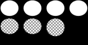
4. Experimental points are depicted clearly and large: in the form of circles, crosses, etc.
5. Scale divisions on the coordinate axes should be applied evenly. The coordinates of the experimental points are not indicated on the axes, and the lines defining these coordinates are not drawn.
6. The scale is chosen so that:
A) the curve was evenly stretched along both axes (if the graph is a straight line, then its angle of inclination to the axes should be close to 45);
b) the position of any point could be determined easily and quickly (a scale at which the graph is difficult to read is considered unacceptable *).
7. If there is a significant scatter of experimental points, then the curve (straight line) should be drawn not along the points, but between them - so that the number of points on both sides of it is the same. The curve should be smooth.
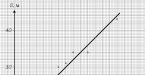
Example 7. Suppose you want to build a path dependence graph S from time t with uniform body movement. Experimental data are given in table. 4. Two options for the dependence graph S(t) – formatted with errors and correct – are shown in Fig. 4 and 5.
Table 4
|
S, m |
The main, most typical mistakes made by students when constructing graphs (Fig. 4):
the directions of the coordinate axes are incorrectly selected: time t is the independent variable (argument) and should be plotted on the x-axis (horizontal), and the dependent variable (function) is the path S– along the ordinate axis (vertical);
the y-axis does not indicate the delayed value (time t) and its units of measurement ( With), and on the x-axis are the units of measurement of the path S (m) – see paragraph 2;
the area of the drawing is not fully used (since it does not follow from the example conditions that the coordinate axes should start from zero values, the origin of coordinates should be shifted and, due to this, the scale of the graph should be increased) - see paragraph 3;
experimental points are not highlighted – point 4;
scale divisions on the time axis are applied unevenly (if there are divisions 0 and 5, then the next one should be 10, etc.) – point 5;
on the path axis there are not scale divisions, but the coordinates of experimental points; extra dotted lines are drawn - see also paragraph 5;
the graph is compressed along the x-axis due to two reasons: an incorrectly chosen origin (point 3) and an unsuccessful (too small) scale - point 6, A;
An extremely inconvenient time scale has been chosen, which makes reading the graph difficult - point 6, b;
experimental points are connected incorrectly: the dependence of the path on time during uniform motion is obviously linear, and the graph should be a straight line - point 7.
A correctly designed graph is shown in Fig. 5.

* The scale is convenient for reading a graph if the unit of value plotted along the axis contains one (or two, five, ten, twenty, fifty, etc.) linear unit - a millimeter or centimeter. The inconvenient but often used by students scale – 15 or 30 – should be avoided. mm per unit value.
Graphing
When performing experiments in laboratory work, it is often necessary to construct graphs of functional dependencies of the form Y=f(X).
In this case, you should be guided by the following rules:
1. The abscissa axis (horizontal axis) shows the values of the independent variable (X), and the ordinate axis shows the values of the function (Y).
2. The dimensions of the graph, the thickness of the points and connecting lines should provide the necessary accuracy of reference, as well as ease of use of the graph.
3. All points on which the graph is plotted must be marked on the graph. In this case, you should not specifically put aside the values corresponding to the points on the axes.
4. The plotted points are connected by a smooth curved line, that is, when constructing the line, smoothing should be used, taking into account the general nature of the resulting dependence. In this case, some points plotted on the graph may not fit into the resulting curve (due to inaccuracies in measurements at these points). By taking measurements at multiple points, smoothing reduces the impact of these inaccuracies. Figure 1 shows examples of constructing graphs using the same points, correct (Fig. 1, a) and incorrect (Fig. 1, b). The thickness of the dots in the example was chosen to be large for clarity of presentation.
5. The values of the X and Y quantities should be marked on the coordinate axes, and the units of measurement should be indicated in convenient quantities. To express a measured quantity using a numerical value, it is advisable to use decimal multiples and submultiples, derived from the base unit and expressed in numerical values between 0.1 and 1000. This approach provides the most convenient perception of numerical data.
For example: instead of 50000 Hz it is more convenient to use 50 kHz, instead of 2·10 -3 A - 2mA.
6. If two dependencies are plotted on one graph Y 1 =f 1 (x) And Y2= f2(x) and the value intervals in which the Y1 and Y2 values are located differ from each other by more than 1.5 times, for each of these functions its own scale should be plotted on the ordinate axis (otherwise the graph errors for each of the dependencies will be very different from each other ). Figure 2, a shows an example of the correct construction of a graph, and Figure 2, b - an incorrect one (the thickness of the points in the example is chosen to be large for clarity).
5. The graph must be provided with a signature that contains information about which dependence was constructed and for which device.
Calculating the graph scale
The accuracy of the count depends on the size of the graph, but the ease of use may suffer. Therefore, the scale of the graph is calculated based on real conditions.
When constructing instrument calibration graphs, the error introduced by the graph (δ gr) is chosen to be less than the error of the instrument itself (δ pr) by approximately 5 times. In this case, the total error δ Σ (taking into account the error introduced by the graph) will differ insignificantly from the error of the device itself:
![]()
Drawing a graph on graph paper.
In the case of plotting a graph on graph paper, the absolute error of the graph in units of length is chosen equal to Δl=0.5 millimeters (half the division value of the millimeter grid). Then, taking into account the accepted conditions, the scale of the graph can be calculated using the formula