Installation of the panel in the apartment. Electrical circuit board
We mount the electrical panel ourselves
The importance of the electrical panel in the apartment in the power supply system of the house is extremely high. The wiring will not be able to function efficiently and fully without proper distribution of electrical energy consumers, and fire and electrical safety will be minimized in the absence of the necessary protection elements. Of course, it will be better if specialists will be engaged in laying wires and installing equipment, but with some study of this issue (this article will help you with this), you will be able to independently install the electrical panel with your own hands without much effort and cost by assembling a simple electrical circuit. The main thing is to figure out what power supply schemes are, what equipment you need to choose, how to calculate electrical loads, how to distribute them correctly and evenly.
General questions about electrical panels
At the moment, there are two types of electrical panels. The first - old and fading into oblivion - a panel with fuses (or plugs), which were disposable, and they had to be unscrewed for replacement, and modern devices equipped with systems of packet switches (automatic machines). Of course, it is better to use modern technologies, since they surpass outdated systems in terms of reliability, safety and durability, and they take up less space, but they are not repaired. In stores, you can buy shields with built-in circuit breakers, as well as empty "boxes" and already install the necessary equipment yourself.
An electrical panel in an apartment, the power supply scheme of which can be varied, and the number of consumers and their power may increase over time, should be selected with additional places for circuit breakers.
An introductory machine, usually capable of simultaneously disconnecting both "phase" and "zero", should be selected based on the total load of the apartment. The value of its current and protective characteristics is higher than that of auxiliary machines. As a rule, an automatic machine for 32-40 amperes (about 7 kW) is suitable for two- and three-room apartments, if the load is less, the machine can be taken for 25 or 16 amperes.
As for the auxiliary circuit breakers installed on the "phase", they are necessary to protect a separate room or device. Experts advise installing such an automatic machine for each consumer whose power exceeds 1.5 kW (heating tanks, washing machines, and so on). A table of approximate loads of electrical appliances is located below.
Table 1 - approximate capacities of household appliances.
An RCD (Residual Current Device) is an extremely useful device if you need to increase the level of electrical protection at times. They react to the slightest leakage of currents and voltages, instantly de-energizing the circuit. If there are bathrooms and children's rooms in the house, equipped with electrical appliances,.
 RCD power distribution
 Installation and construction of the shield
The electrical panel for apartment abb or legrand is of two types:
- Closed (recessed into the wall).
- Open (the shield is attached directly to the vertical surface).
The choice of the type of installation mainly depends on the type of wiring - if the open-type wiring is ideal, the installation of an overhead shield will be ideal - such a shield does not require special preparation of the place, fastening to the wall is carried out using ordinary dowel-nails or screws "self-tapping" (it all depends on the material of the wall) ...
If the wiring is of a hidden type (i.e. built into the wall), then the best option would be to install a built-in shield. Here everything is more difficult, since you have to hammer the walls. The main thing is not to forget to make sure that the thickness of the wall allows you to install the shield. After creating a niche, it is coated with a fixing solution of gypsum or alabaster, and already a "box" is built into such a bed. It is more convenient to use a plastic shield. The upper part should contain input machines, under which the counter is located. It is secured with screws. The installation of the meter is carried out after the end of the work related to the wiring device. This is due to the filling.
The electrical panel must be installed on a hard surface - in a place where it is easy to access and maintain.
According to the norms, the location of the shield, it is installed away from the water and gas pipelines. It should be located on a flat wall surface with an angle of inclination of no more than 1.5 degrees at a height of about 1.5 meters from the floor. If it is not possible to place the meter far from the places of potential damage, then it can be placed in a cabinet equipped with an observation window. Fastening of wires is allowed using bandage binding.
For wiring in the attic, it is necessary to leave a short wire, because it is not allowed to twist the wire into a coil. If you are installing electrical wiring in the attic, the cable is placed in a metal pipe with grounding.
As for the materials from which the shields are made, it can be either metal or heat-resistant plastic. The second option is more convenient in installation and operation, safer, and its appearance is attractive.
So, we have dismantled the installation of the box itself, now we will figure out how the circuit of the electrical panel is arranged. 
In principle, all electrical circuits of panels are of the same type, but there are main factors by which they are assembled, these include:
- the number of consumers of electrical energy;
- total power consumption of electrical energy;
- the power of each consumer;
- place of installation of the electrical panel;
- number of phases;
- the presence of a grounding conductor;
- the presence of a metering unit for electrical energy.
The voltage is supplied to the input automaton (it is better if it is two-pole) and goes to a single-phase electricity metering unit, from where it is fed to the RCD. Further, there is a phase splitting and direct distribution of loads using circuit breakers and additional RCDs. For example, there will be machines separately for lighting, for sockets and for powerful consumers.
The device of the electrical panel with a three-phase power supply system is similar, only the introductory machine, the RCD and the electric meter will be three-phase, and the whole system will be larger both in terms of dimensions and in the number of machines and connecting conductors.
We start the internal installation
Now let's figure out how to properly assemble the electrical shield. First and foremost, a din-rail is installed in the shield using self-tapping screws. From itself, it is a metal plate, to which all switching devices will subsequently be attached. To create the required length, it can be easily cut with a hacksaw for metal.
In addition to the din-rails, terminal blocks are attached to the shield body (in a different way, distribution busbars). Their role is to connect neutral conductors. If an apartment or house of an old model and the entire system is made only by a phase (3 phases) and a working zero (performed with a blue wire), one terminal block is enough. If the system is made according to the rules and there is an additional yellow-green conductor (protective zero or ground), then it is necessary to install another bus. At the moment, there are tires on sale, the design of which allows them to be mounted on a din-rail, like machines.
After mounting the din-rails, we proceed to fixing the circuit breakers. The modern design will make it possible to do this very quickly, it is enough to pull off the latching device on the upper side of the machine with a flat screwdriver, put the machine on the DIN rail and remove the screwdriver. Removal is carried out in the same way.
Assembly instructions

The connection can be made in three ways:
- With the help of stranded copper wires with ferrules type NSHVI.
- Make U-shaped jumpers from pieces of copper wire with your own hands.
- With the help of special insulated busbars called combs. Such a bus is convenient in terms of installation and does not take up much space, plus several times it reduces the number of connecting wires.
Following actions:

What else do you need to know?
Installing an electrical panel and assembling it is not only about the ability to correctly assemble circuits. You also need to know some of the nuances in order not to regret the time and effort spent later.
It should be recalled that it is necessary to assemble and install the Legrand, ABB electrical panel or equipment of another company strictly on the disconnected power line, after checking the absence of voltage.
To connect the assembled shield to the operating system, it is necessary to involve employees of the relevant organizations. For apartment buildings, these are representatives of the HOA or ZhEK.
As a result, after the end of the entire assembly and connection process, you need to close or screw the cover and check your work by applying voltage to the live parts of your shield.
 Wiring diagram with three input phases
  Single-phase connection diagram
  Wiring diagram in the apartment
However, I would like to touch on it again. On the Internet, you can find a huge number of different examples of the implementation of apartment panels, especially on YouTube. Some craftsmen go to the point of absurdity when drawing up apartment boards.
In my opinion, this topic will primarily be useful to customers, because the customer, often, is not particularly versed in electrics and is ready to believe everything that an electrician offers. And negligent electricians are only happy to lay hundreds of meters of cables in your apartment and earn as much as possible from this.
Some people put protective devices on almost every outlet, and then brag about their work. Do you need it? Why waste money when it could be spent on more useful things.
There are 2 main types of apartments:
- apartments with gas stoves (6 kW);
- apartments with electric stoves (10 kW).
Luxury apartments are quite rare, so they need to be considered individually. I was once sent to look at the project of a private house, in my opinion for 250 kW
In accordance with the latest standards, 6 kW are allocated for an apartment with a gas stove, and 10 kW for an apartment with an electric stove.
What is 6 or 10 kW? This means that at the same time you can turn on electrical appliances with a total power of up to 6 kW if you have an apartment with a gas stove or 10 kW if you have an electric stove.
Regardless of how many household appliances you have, in general you cannot use more than 6/10 kW. In most cases, this is sufficient. It is extremely rare that you decide to do your laundry, reheat food in the microwave, drink tea, etc. If you turn everything on at the same time, then, of course, the input circuit breaker will work and turn off the entire apartment. In practice, this practically does not happen.
There is a heading on my youtube channel: How much do they consume? If you are interested, see how much household appliances actually consume. Soon I will add a video about a toaster, multicooker, candy bar, coffee grinder and other small household appliances that I have at home.
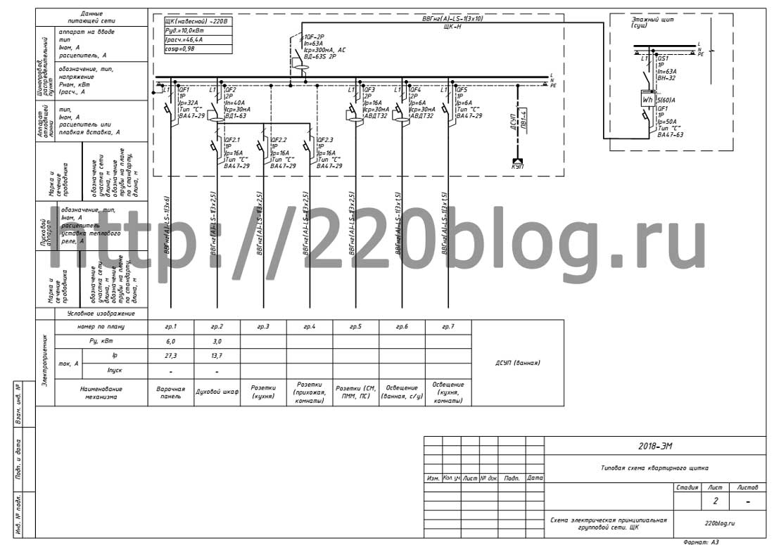
A typical electrical panel diagram for an apartment with a gas stove will look like this:

At the input to the apartment panel, I propose to install a fire-fighting selective RCD of 300 mA. You shouldn't skimp on this product. It's not cheap, but think about what could happen to your apartment in the event of a fire? Anything can happen and there may be problems with household appliances, and problems with electrical wiring ...
PUE 7: 7.1.84. To increase the level of protection against fire in case of short circuits to earthed parts, when the current value is insufficient to trigger the overcurrent protection, at the input to an apartment, individual house, etc. it is recommended to install an RCD with a tripping current of up to 300 mA.
To reduce the cost of the apartment panel for the first three groups, a common RCD is provided.
This group includes:
- oven;
- kitchen sockets;
- sockets of rooms.
The so-called "wet sockets" are allocated in a separate group, which has its own difavtomat. For example, the power of a washing machine is about 2 kW, but this does not mean that it consumes such power during operation. The washing machine consumes 2 kW only at the time of heating the water, which is about 10% of the time of the entire washing cycle; during washing, consumption is about 150-300 W. The mode of operation of a dishwasher (PMM) is similar to the operation of a washing machine. The PMM consumes the greatest power during water heating. The power of the electric heated towel rail is 100-300 W. There is no need to worry that a 16A difavtomat is not enough for an outlet group in which you can dry a washing machine, dishwasher, or electric towel.
We also provide a separate line with protection with a difavtomat for lighting a bathroom or a bathroom and a toilet.
For lighting the kitchen, corridor, rooms - a separate group, protected by an automatic switch. For lighting, a 6-10A circuit breaker is sufficient.
Why not put a common RCD instead of two difavtomats? I don't think it's worth it, because the probability of triggering these groups is higher than the first three. If we suddenly have problems with the washing machine, then only this group will turn off, which will allow us to quickly identify problem equipment and will not cause discomfort to those who are in the bathroom.
Regardless of how many rooms there are in the apartment, 2 lighting groups and one outlet group are enough for all rooms. For 1-3 room apartments, this rule should always be followed. There are no powerful consumers in living rooms, so there is no point in splitting several groups.
The electrical panel diagram for an apartment with an electric stove will look like this:
This scheme differs from the previous one by the presence of a separate group for the electric stove, protected by a 32A circuit breaker.
These are typical schemes of apartment boards, which do not have anything superfluous, are made in accordance with all norms and requirements, are economical and easy to use. In cases of the presence of air conditioners, underfloor heating and other wishes of the customer, these schemes are very easy to transform into more complex ones.
To implement these schemes, a modular board for 18 modules is sufficient. When completing the shield, always provide for spare places for the installation of additional devices. May come in handy in the future.
For more information about the schemes of apartment shields, see the video:
I also want to note that this scheme can be modified, made a little more expensive, but I will talk about this in a separate video.
) for all apartments located on the staircase.
However, modern trends have changed the approach to the distribution of electrical energy and they began to equip electrical panels directly in apartments. This was due to several main reasons, namely:
- Lack of space in floor panels due to too much electrical equipment ( , machines, counters, and so on);
- The need to preserve rather expensive electrical equipment from vandalism and theft;
- Convenience - to turn off a group of consumers in an apartment, there is no need to go out into the staircase;
There are electrical panels for hidden and outdoor installation.
Distribution of the apartment electrical network into groups
To increase the safety and reliability of power supply, as well as more convenience during operation and repair, the electrical network of the apartment is divided into groups. The most popular distributions of the apartment electrical network into groups are as follows:
- By types of consumers - very well suited for small apartments, where consumers are divided into the following groups: lighting, kitchen sockets, air conditioner, boiler, washing machine, sockets in rooms, and so on;
- By premises - it is most advisable to use in large apartments with relatively high energy consumption in each room: kitchen, corridor, technical rooms, rooms, and so on;
- Quite often, a combined version is also used, consisting of the methods described above;
The purpose of the apartment board is to individually cut off the supply voltage for groups of electrical receivers, metering of electricity, indication of the presence of phases, and so on.
Very often, to implement protection and shutdown schemes, they resort to the two most common options:
- All sockets are connected through an RCD to one machine. Lighting circuits are connected to another machine without using an RCD, and the third is used to power powerful consumers, such as a washing machine, boiler, air conditioner and others.
The advantages of such a connection scheme:
- Simplicity;
- No need for additional junction boxes;
- Low cost;
Disadvantages:
- In the event of an accident, the entire group of consumers will be left without power supply;
- The process of detecting a fault on the line is more complicated;
- The circuit breaker combines the functions of supplying lighting and sockets with power distribution in junction boxes. In this case, potentially dangerous circuits must be equipped with RCD residual current devices.
Advantages:
- Each area of the power supply is under control, which contributes to good management and quick finding of faults on the line;
- Maximum protection;
- In the event of an accident, almost all devices will remain connected to the network;
Disadvantages:
- The dimensions of the shield are increasing;
- The price of the project increases significantly;
Electrical circuit board
Below is a schematic diagram of an apartment switchboard:
The panel diagram is made for single-phase input. The diagram is conventionally designated: L - phase of the supply voltage, N - neutral or neutral conductor, PE - protective ground.
More detailed diagram below:

An introductory circuit breaker is a circuit breaker designed to completely turn off the entire apartment in case of an emergency or to forcibly turn off the entire apartment by the user himself.
An electric meter is a device for metering the consumption of electricity in a given room. The measurements are carried out in kWh. They can be both mechanical and electronic. Electronic electricity meters can be programmed and transmit energy consumption data to other electronic devices.
Differential automatic device is a device that combines the functions of a circuit breaker and an RCD residual current device.
Busbars for connecting wires - they complete electrical panels with at least two. One for connecting ground wires, and the second for neutral wires.
In the specified dashboard, there are two branches for separate groups (QA4, QA5). Group 1 has three branches (QA4) and group 2 has two branches (QA5). This option can be suitable for certain functional groups of the bath and kitchen.
Examples of schemes for apartment panels
The electrical installation of the apartment switchboard is carried out on the basis of the electrical diagram. If the shield is purchased assembled, then the electrical schematic diagram must be attached.
An example of a simple apartment electrical panel using an RCD is shown below:

For clarity, the cross-sections and brands of cables are shown that can be used for individual cable lines.
Shown on the right is the standard configuration of a regular apartment. At the entrance to the apartment, they are installed in series with a differential circuit breaker or a conventional circuit breaker. There can be several consumer groups in the board.
In the example shown, a group of lighting and sockets protected by two BA63 circuit breakers with a rated current of 16 A, as well as an automatic device with a rating of 25 A to protect an electric stove.
Quite often, air conditioners or washing machines are distinguished into a separate group.
The electrical panel diagram for a multi-room apartment will look something like this (diagram on the left):

Differential circuit breaker is installed to protect kitchen outlets using a large number of different electrical appliances. Differential load switch protects other objects - bathroom lighting, room switches and other electrical equipment.
A more complex circuit for a switchboard for a multi-room apartment is shown below:

In this case, an RCD VD63 with a differential current of 300 mA is installed at the input. This is due to the fact that the leakage current can be quite high due to the large length of the line and when installing an RCD with a lower leakage current, false alarms are possible.
The first three circuit breakers are needed to protect the lighting circuits. Differential automatic device with a leakage current of 10 mA is used to protect the electrical equipment of the bathroom. This low trigger current is necessary due to the increased risk of electric shock in the bathroom. A group of UZO VD63 and three automatic devices protect the sockets. Three-phase automatic machine VA63 and UZO VD63 protect powerful consumers, such as an electric stove. The last line of one VD63 RCD and two VA63 circuit breakers are designed to protect the circuits of utility rooms and other rooms.
You can proceed to the direct assembly of the shield after drawing up a diagram of the shield, laying all electrical wiring routes along the grooves, ceiling, etc. Some people order ready-made solutions according to pre-calculated groups and loads, and then all that remains is to connect the supply and outgoing wires. The article will consider the process of independent performance of all types of work on the assembly of the shield.
Let's take the averaged data for an apartment of a small area, which we will operate with when assembling the dashboard:
- ⚡ number of groups - 8-10
- ⚡ there is an RCD or difavtomat in the dashboard
- ⚡ automatic switches are installed on outgoing groups
- ⚡ the total number of modular places for devices - up to 20
Electrical panel assembly tool
 The tools and devices that you will need to use in order to efficiently and competently assemble the shield with your own hands:

It is advisable at the preliminary stage to bring the cables into the shield not at random, but in order, according to the numbered groups.
Let's say from the first to the tenth group, from left to right. So that the bundle of cables does not interfere with the assembly process, make an impromptu hook from the materials at hand on the side of the shield, and bend the cables to fix them on this device.
We start directly to work.
The procedure for assembling an electrical panel 220v
1. Stripping the cable
With a knife, remove the outer insulation from all cables inserted into the shield and mark the cores in groups. Bend the numbered veins and fasten them to a homemade hook on the side of the shield. 
2.Trying on distances
Before connecting the wires, first try on and estimate the places where the modular equipment will stand and how long the wires are needed before them.
 Install the DIN rail, zero rail and grounding rail. Do not fasten or fasten anything, just try on. Your task is to understand the general location of the machines and the location of the wires. What you should pay special attention to:
- ⚡ distance between rows of machines
- ⚡ distance between machines and zero tires
Try to make these distances not too small, otherwise in the further installation process it will be extremely inconvenient to start and connect wires.
3.Bus of grounding and neutralization
After preliminary fitting, mount and fix the zero bar and the ground bar in the shield. Above the bus terminals, sign the group numbers.
 Since the grounding wires never burn out, the grounding bus can be mounted on top of the shield, without any wire reserve. But zero, it is better to place it at the bottom. In case of unforeseen circumstances, you will have a certain amount of wire and by moving the bus higher, you can turn off all the equipment again without replacing or building up conductors.
Select the neutral and grounding conductors from the bundle of cleaned wires (the neutral conductor is usually blue, the grounding conductor is yellow-green), clean them with an insulation stripper and alternately connect them to the busbars. No extra stocks or extra bends should be done. 
4. Assembly of modular equipment in the switchboard
Mount and fix DIN rails. Previously laid protective conductors (neutral and ground) must be behind the din rail. On the DIN rail, you consistently snap the machines according to your groups. 
Stick to the following modular hardware layout:
- ⚡ the first is an introductory circuit breaker or load breaker
- ⚡ then comes the voltage relay (if you provided it in the circuit)
- ⚡ further automatic machines of the most powerful consumers (hob, oven, split system) or RCD with differential automatic devices
- ⚡ simple machines for sockets and switches are located in the bottom row
Try to place all automation in the center, leaving more space on the sides for laying conductors or for installing additional modular devices in the future.
To prevent modular equipment from traveling on a din rail, it is very convenient to use the clamps. 
5.Connecting wires
Start the connection from the top row. Select from the bundle of phase outgoing conductors those groups that go to the upper row and tie them into a bundle with cable ties.  Lay the bundle along the edges of the shield, form a comb at the end with the letter G and start the stripped wires from the bottom of the machines. Then install the lower rows of machines and repeat all operations.
6.Comb shank
 For sequential connection of machines located in the dashboard in one row, we use a comb bus. We cut it to the required length according to the number of machines in the rows and tighten the screws by inserting it into the upper terminals of the machines.
Please note that if you have budget vending machines without an additional contact specially designed for a comb shank, then the shank must be inserted into the vending machine in such a way that the protruding part of the shank looks at you.
Then you can easily bring a wire into the contact of the machine along with the contact of the bus, and when tightening the machine it will not bend it and the conductor will not come out of the contact. 
7. Internal switching of the panel
To further disconnect the commutations, use pieces of the prepared wire PV3 * 10 (for connecting the very first machines in a row), PV3 * 1.5 (for zero contacts of the voltage relay) and PV3 * 2.5 for difavtomats and RCDs of individual groups. 
If solid wires are used, then bend the end of the wire entering the machine twice, thereby increasing the useful area of contact with the contact. 
Well, for stranded wires, be sure to use ferrules. 


After the completion of the installation work on the wiring of power cables, the final and no less crucial moment comes - the assembly of the electrical panel. Let us analyze, with specific examples, how the switchboard is completed and installed for a private house or apartment.

Important information
Before you learn how to assemble an electrical panel, you should familiarize yourself with their main types. By the method of installation, they are divided into:
- built-in;
- waybills.
According to the material used to manufacture the case:
- metal;
- plastic.
An electrical panel in a private house or apartment can be of any of the above types. When choosing it, it is taken into account how the electrical panel will be installed and its further operation. It would not be superfluous to say about the manufacturers, both of the cases themselves and of the components.
The safety and reliability of the equipment largely depends on the quality of the purchased materials. The most famous brands in this area are:
- "ABB";
- IEK;
- "Legrand";
- Schneider Electric.
These companies, over the years of presence in the electric power equipment market, have proven themselves from the very best side.
At the end of the introductory part, we list the main components on the basis of which the electrical panel is assembled. These include:
- automatic switches;
- frame;
- fastening rail for automation (DIN rail);
- power wiring of various sections;
- power distribution busbars (PE and N);
- electric meter.

Depending on the specific purpose, additional elements can be installed in the shield, or vice versa, some will not be required. For example, an intermediate switchboard usually does not require a meter to be installed. More complex designs may include elements of alarms and other monitoring devices.
Purpose of equipment and importance of calculations
The main purpose of the switchboard is to protect the home electrical network from overloads, and the premises itself from fire. It is important to understand here that the design and calculations of all parameters must be carried out with the utmost care.
For example, if the cross-section of the wiring is incorrectly calculated and the installation is insufficient, the load on the network can cause a fire in the insulating layer. The other extreme is the installation of machines that are too powerful. In such a case, electrical appliances with high energy consumption may burn out the sockets.
Large wiring, not designed for specific conditions, also leaves the network defenseless. With a load jump, protective actions may not occur since the circuit breakers will not have time to respond to critical indicators in time.

Create a schema
An electrical panel in a private house or apartment begins with design work, namely, creating a wiring diagram. At the same time, it is desirable to adhere to a rational approach to the distribution of future elements. This will not only make the device more compact, but also save on wiring. At this stage, the place for the installation of the finished equipment is finally determined.
How to calculate the number of places in the electrical panel
A rational approach to the design of a switchboard, first of all, implies a competent calculation of the number of meters for the installed equipment. In practice, this is not difficult, since all modern components of electrical panels have strictly uniform dimensions.
Here one module is counted as a unit of measurement. This area is equal to the space occupied by a circuit breaker with one pole. Its width is 17 and a half centimeters. This standard is international and is suitable for any modern electrical components.
For the convenience of making calculations, we offer you a table with the main components that may be required in a switchboard.
Module size table:

An example of a simple calculation for a switchboard
For a practical understanding of how such calculations are carried out, we will give a small example for a simple distribution panel in an apartment or private house.
The figure shows a circuit in which an electric energy meter is included. According to the conditions of our task, the input of the main line was made using a VVGng cable with a cross section of 3 * 6 square millimeters. Now let's count the modules installed in the shield and the space they occupy:
- upstream circuit breaker with two poles = 2 modules;
- then an electricity meter is installed = 6 modules;
- after the meter, two RCDs = 4 modules;
- circuit breakers with one pole in the amount of six = 6;
- zero buses intended for two RCDs = 2.
Let's sum up by summing up all the modules and we get - 20 places and this is for the simplest distribution board. Since all experts recommend that a certain margin be included in the calculations, in case additional components are installed, we understand that the housing for the dashboard must be purchased for at least 24 seats. It is advisable to increase this value to 40 in order not to face the problem of lack of space later.
Source avatars.mds.yandex.netA few words about RCD
When designing and installing, it is important to remember one more point - the inclusion of an RCD into the circuit. This abbreviation stands for Residual Current Device. Like a circuit breaker, an RCD is a protection device, but much more sensitive.
The circuit breakers are designed to work with short circuits in the network. The current under such loads can reach hundreds of amperes. However, even a couple of tens of milliamperes can have a detrimental effect on human health. RCDs protect precisely from such troubles.
For example, a child has thrust a foreign object into the socket, and the current will be instantly turned off. Plus, it is necessary to add a type of grounding in the apartment. A system with three phases and zero (international standard TN-C) is already widely used. The RCD in such a system is the only and reliable protection against overloads.
Toolkit preparation
To carry out the correct connection of the machines and the rest of the work with the switchboard, you will need some tools. To check the functionality of the circuit after connecting all the components, use a multimeter.

A Phillips and a flat head screwdriver is required to work with screw connections. Stripping the insulation is done with a special tool or a well-sharpened knife. It doesn't hurt to have pliers and a hammer on hand.
Minimum requirements when designing a switchboard
In addition to the importance of preliminary calculations, which we talked about above, when creating a flap diagram, it is necessary to take into account some nuances. In general, they do not require strict implementation, however, when introduced into a structure, they greatly increase its reliability and ease of use.
On the one hand, you need to strive for the simplicity of the device, on the other hand, do not neglect the advice of experienced specialists. First of all, this concerns the division of connections into several power lines. In an emergency, this approach allows you to quickly find the place of failure. An important point with several lines is the possibility of only partial loss of energy supply to the premises.
This separation rule also fully applies to circuit breakers. The optimal connection of the machines in the switchboard is carried out according to the following scheme - each room separately. In this case, it is desirable that a separate circuit breaker be installed on the line of light and sockets.

The main connection of the machines in the dashboard is made through one central switch. Do not forget about appliances with increased energy consumption - hobs, washing machines and the like. All of them are connected to the network through a separate machine.
Assembling the shield
Having developed the circuit and having decided on the components, you can proceed to the direct assembly. It is important to note here a point regarding the installation of an electric meter. As a rule, this is the responsibility of the energy sales organization. In some cases, you can install the meter yourself, but for this it is necessary to obtain the appropriate permission and draw up an act.
The installation of a switchboard consists of eleven steps:
- Mounting the enclosure on a wall or in a prepared niche.
- Plant supply wiring to the housing on one side and lines from rooms, as well as powerful household appliances, on the other.
- Stripping the wiring to ensure reliable contact with the terminals of the machines.
- Mounting a mounting rail (DIN-rail) inside the switchboard housing.
- Fastening all components to the bus, including the meter. This operation is not difficult since the devices are either put on the rail, with subsequent fixation, or immediately snapped on.

- Installation of grounding and zero busbars.
- Cutting lengths of wires for jumpers.
- Connecting the entire circuit into a single circuit. Some are confused by the question - how to properly connect the machines in the electrical panel. Meanwhile, the answer to it is quite simple, the main rule is that the phase input and zero connection are carried out using the upper terminals.
- Visual inspection of the quality of the joints and, if necessary, tightening the screws.
- Connection and sealing of the electricity meter in the presence or directly by the representative of the energy sales organization.
- Test start of the system.
After the test run, it is necessary to carry out a careful inspection of the switchboard and the entire system again for a burning smell, sparking or tripping of circuit breakers. If none of this is revealed, the shield is assembled correctly, and you can safely use it.
Video description
More about the assembly of the shield in the video:
Replacement and repair
The above procedure dealt with the design and installation of a switchboard from scratch. Such an installation is necessary in new buildings or residential premises after major repairs. Often, such radical measures are not required, it is enough to make minor repairs or expand the functionality of an already installed device.

Replacement of machines
The most common procedure when repairing a switchboard is to replace installed circuit breakers. Before carrying out any work, it is necessary to turn off the packet switch.
When deciding how to connect the machine to the wiring, do not forget about the rule that was indicated above. It is also necessary to carefully study the labeling of the device and purchase a similar one with the same denomination in the store. Do not make the mistake of purchasing a more powerful circuit breaker - this will inevitably lead to an emergency. To unload the network, it is better to create a separate line with your own machine.
Be careful not to completely de-energize the premises and injure yourself when working. In this case, safety precautions must be strictly observed. As for the packet switch, it cannot be replaced or repaired on its own, only specialists can do this.
On our website you can find contacts of construction companies that. You can communicate directly with representatives by visiting the Low-Rise Country exhibition of houses.
Replacing the jumpers
If you make the internal connections of such elements as circuit breakers, according to the classical scheme, then pieces of wire with bare ends are used. Jumpers are made of them, forming target groups from the components.

Now these elements are connected more reliably and competently using special insulated copper busbars. Electricians call them "combs" because they look like combs with a rare tooth. The distance between the contacts of such a bus corresponds to one module or one and a half value.
"Comb" allows you to connect several linear automata into a single structure and the contact is carried out on a neutral wire or phase. The length of the tires varies depending on the task at hand. Typically, twelve to sixty modules can be connected.
"Combs" are produced in three types:
- phase;
- zero;
- universal.
The first type connects the phase conductors and is colored gray, the second makes a contact between the neutral conductors. This type of bus is colored blue, like the zero core of the power line wiring. Universal "combs" have double marking and can be installed on conductors of both phase and zero type.
These connecting elements can be used not only for the "bundle" of automatic circuit breakers, but also for various contactors, RCDs and differential circuit breakers.
If, after carrying out repair work and turning on the switchboard, a short circuit occurs, you should carefully examine the insulation of the connecting wiring. In case of damage, the insulating layer can be reanimated with insulating tape.
Video description
You can try to make the jumper yourself, for example, as in the video:
Changing the case
The second, no less common procedure is replacing a dilapidated switchboard housing. Most manufacturers equip them with a mounting rail, as well as power distribution rails. When buying, pay attention - if the DIN rail is made of plastic, then it is better not to purchase such a case. An extremely unreliable option that quickly becomes unusable.

The size of the acquired body deserves a separate word. Ideally, even at the stage of developing a circuit, a margin for expansion should be included in the form factor. Therefore, when replacing, this circumstance must be taken into account. For example, if the scheme turns out forty modules, then it is better to buy the case for sixty.
This will allow new modules to be installed and separate lines to be drawn. This solution may be required when purchasing more powerful household appliances. It will also be possible to include devices in the network that are designed to operate a cable with different technical characteristics than in the general system.
Adequate space inside the housing makes it easy to install and replace elements. In addition, operational safety is increased by reducing the risk of overheating of components.

Now it will not be superfluous to turn to the advice of professional electricians who will help you to more competently disconnect the electrical panel and simplify its operation.
When installing a switchboard in an apartment or house, it is advisable to create a diagram of all connections with understandable designations. It can be drawn or printed on paper and glued to the inside of the cabinet door. This will allow, in the event of an emergency and the absence of the owner, almost anyone can quickly turn off or turn on the energy.
For ease of maintenance and repair work, all groups of wiring inside the switchboard are grouped according to the purpose of the lines. Grouping can be done using electrical tape or plastic clamps. Each group is attached with tags with appropriate inscriptions. When repairing the wiring, you don't have to puzzle over which wire is responsible for what and to avoid unpleasant mistakes.
Once again, we remind you of the importance of the correct connection of the circuit breakers - the input conductors are wound up from above. For reliability, inspect the markings on the devices, most manufacturers place a correct connection diagram on them and the question of how to connect the machine in the dashboard disappears by itself.

After a test run, an assembled or repaired switchboard, it is left open for several hours. In this case, it is desirable to increase the load on the network to the maximum. After a couple of hours, you can check if the components of the shield are heating up.
With correct assembly and calculations, there should be no elevated temperature. Otherwise, it is necessary to turn off the shield, and look for the source of the problem. If this is not done, a short circuit is inevitable.
It is necessary to tighten all screws inside the switchboard about once every six months. This is especially important when using aluminum wires in the network.
To create a high-tech distribution board, it is recommended to install a voltage relay in it. This device will monitor the performance of the network and in the event of a critical surge or voltage drop, it will automatically disconnect the load. After the restoration of the nominal values, switching on will occur. Thus, you can reliably protect electrical appliances with increased requirements for the mains voltage.

Once again, pay attention to the dimensions of the case, as mentioned above, it should be "for growth" providing the possibility of expanding the system. The more spacious housing reduces mutual overheating of the elements and increases their service life.
Pulling out the contact fittings can be combined with cleaning the inside of the switchboard housing. Dirt causes the elements of the shield to heat up more, and dust and cobwebs can become sources of short circuits.
Video description
Another example of assembling the flap in the video:
Conclusion
In conclusion, we can say that with due care, self-installation of a switchboard is a completely feasible event. The main thing is not to forget about safety precautions and make the right calculations. However, in order to be guaranteed to avoid mistakes, it is better to entrust this business to professionals.