Description of the operation of the electronic ballast. Scheme for connecting fluorescent lamps to a ballast
Classes, with sufficient luminous flux and at the same time economical, prompted, one might even say, some searching and trying out options. At first I used an ordinary small clothespin lamp, changed it to a small table fluorescent lamp, then there was an 18 watt fluorescent lamp of the "ceiling - wall" version of Chinese production. I liked the latter most of all, but the fastening of the lamp itself in the armature was somewhat underestimated, literally by two to three centimeters, but “for complete happiness” they were not enough. I found a way out in doing the same thing, but in my own way. Since the work of the existing electronic ballast did not cause any complaints, it was logical to repeat the scheme.
circuit diagram
This is a large part of this electronic ballast, the Chinese did not include the choke and capacitor here.

Actually faithfully sketched from the printed circuit board circuit. The rating of the electronic components that allow this to be done was determined not only “by appearance”, but also by measurements, with preliminary soldering of the components from the board. In the diagram, the value of the resistors is indicated in accordance with the color marking. Only with regard to the inductor, I allowed myself not to unwind the existing one to determine the number of turns, but measured the resistance of the wound wire (1.5 ohms with a diameter of 0.4 mm) - it worked.

First assembly on the circuit board. I carefully selected the component values, regardless of the dimensions and quantity, and was rewarded - the light bulb lit up the first time. Ferrite ring (10 x 6 x 4.5 mm) from an energy-saving light bulb, its magnetic permeability is unknown, the wire diameter of the coils wound on it is 0.3 mm (without insulation). The first start is mandatory through a 25 W incandescent bulb. If it is on and the luminescent one initially blinks and goes out - increase (gradually) the value of C4, when everything worked and nothing suspicious was found, and removed the incandescent lamp, then reduced its value to its original value.

To some extent, focusing on the printed circuit board of the original source, I drew a signet for the existing suitable case and electronic components.

I etched the scarf and assembled the circuit. I was already looking forward to the moment when I would be pleased with myself and glad to be. But, the circuit assembled on the printed circuit board refused to work. I had to delve into and deal with the selection of resistors and capacitors. At the time of installation of the electronic ballast at the place of operation, C4 had a capacitance of 3n5, C5 - 7n5, R4 resistance 6 ohms, R5 - 8 ohms, R7 - 13 ohms.

The lamp "fits" not only in the design, the lamp, raised all the way up, made it possible to comfortably use the shelf inside the niche of the secretary. Comfort in the "room" suggested Babay.
Content:Lighting in large rooms is increasingly carried out using tubular fluorescent lamps. They are able to significantly save energy and illuminate the space with diffused light. However, their service life largely depends on the normal operation of all components. Among them, the ballast circuit of fluorescent lamps is of great importance, providing ignition and maintaining a normal operating mode.
Ballast for fluorescent lamps
Most conventional 50 Hz designs use electromagnetic ballasts for power supply. High voltage is obtained through the reactor when the bimetallic key opens. A current flows through it, providing heating of the electrodes with closed contacts.
These starting devices have a number of serious drawbacks that do not allow fluorescent lamps to fully use their resource when illuminating rooms. Flickering light, increased noise level, unstable light during power surges are created.
All these shortcomings are eliminated by the use of electronic ballasts (), called electronic ballast. The use of a ballast allows you to almost instantly light the lamp without noise and flicker. The high frequency range makes the lighting more comfortable and stable. The negative impact of mains voltage fluctuations is completely neutralized. All flashing and flashing faulty lamps are switched off by the control system.

All electronic ballasts are relatively expensive. However, in the future, there is a visible compensation of the initial costs. With the same quality of the luminous flux, energy consumption is reduced by an average of 20%. The light output of a fluorescent lamp is increased due to the higher frequency and increased efficiency of electronic ballasts compared to electromagnetic devices. The sparing mode of start-up and operation with the use of ballast allows you to increase the life of the lamps by 50%.
Operating costs are greatly reduced as no replacement of starters is required and the quantity is also reduced. When using a light control system, additional energy savings of up to 80% can be achieved.
Typical Ballast Diagram
The design of the electronic ballast uses an active power factor corrector, which ensures compatibility with the electrical network. The basis of the corrector is a powerful step-up pulse converter controlled by a special integrated circuit. This provides nominal operation with a power factor close to 0.98. The high value of this coefficient is maintained in any operating modes. Voltage change is allowed in the range of 220 volts + 15%. The corrector provides stable illumination even with significant voltage fluctuations in the network. An intermediate is used to stabilize it.

An important role is played by a network filter, which smooths out high-frequency ripples of the supply current. Together with the corrector, this device strictly regulates all components of the consumed current. The mains filter input is equipped with a protective unit with a varistor and a fuse. This allows you to effectively eliminate network surges. A thermistor is connected in series with the fuse, which has a negative temperature coefficient of resistance, which provides limiting of the input current surge, during the connection of the electronic ballast from the inverter to the network.
In addition to the main elements, the ballast circuit for fluorescent lamps requires a special protection unit. With its help, the status of the lamps is monitored, as well as their shutdown in case of malfunction or absence. This device monitors the current that the inverter consumes and the voltage supplied to each of the lamps. If during a certain period of time the specified level of voltage or current exceeds the set value, then the protection is triggered. The same happens during a break in the load loop.

The actuating element of the protective unit is a thyristor. Its open state is maintained by the current passing through the resistor installed in the ballast. The value of the ballast resistance allows the thyristor current to maintain the on state until the supply voltage is removed from the electronic ballast.
The control unit of the electronic ballast is powered through the mains rectifier when the current passes through the ballast resistor. Reducing the power of the electronic ballast and improving its efficiency allows the use of a smoothing circuit current. This circuit is connected to the point where the inverter transistors are connected. Thus, the control system is powered. The construction of the circuit ensures the launch of the control system at the initial stage, after which, with a slight delay, the power circuit starts.
Fluorescent lamps at one time made a real revolution in lighting, as in their light output they surpass conventional incandescent lamps by several times. For example, one fluorescent lamp (this is another name for fluorescent lamps) with a power of 20 watts gives a luminous flux that is available only to a 100-watt incandescent lamp. If an incandescent lamp can simply be connected to the network using only a switch cartridge and wires, then a fluorescent lamp, like a “capricious lady”, needs to create special “comfortable conditions”. It must first be prepared for launch, then launched, and after it lights up, constantly monitor its “well-being”. This is done by ballasts (PRA). The most modern and efficient ballast is electronic ballast, which is commonly called electronic ballast.

The word "ballast" in the name of this device may cause some dissonance among some readers, since one of its meanings is a useless load that has to be carried. However, ballast is not always useless, and sometimes necessary. For example, without ballast, any ship would not have the necessary landing and stability, and airships and balloons cannot adjust their flight altitude. By the way, linguists give the origin of the word "ballast" to the Dutch - the nation of sailors and shipbuilders. Therefore, we propose to perceive the concept of electronic ballast in a purely positive way, as something that is really necessary.
Conditions necessary for starting and burning a fluorescent lamp
Let us briefly consider the device of the lamp and find out what processes take place in it.

Fluorescent lamps can be of various shapes, but the most common are linear, which look like an elongated sealed cylinder made of thin glass. The air is pumped out from the inside, but inert gases and mercury vapor are pumped in. The mixture of gases in the lamp is under reduced pressure (approximately 400 Pa).
From one and the other end of the lamp there is an electrode (cathode) of complex design. Each cathode has two pin connectors on the outside, and a tungsten spiral with a special emission coating is placed between them inside. If a voltage of 220 V is applied to the opposite cathodes, then nothing will happen in the lamp, since the rarefied gas simply does not conduct electricity. It is known that two conditions are necessary for the flow of electric current:
- The presence of free charged particles (electrons and ions).
- The presence of an electric field.
When we apply an alternating voltage of 220 V to the cathodes, then everything will be in order with the electric field in the bulb, since it exists in any environment, even in a vacuum. But the main "difficulty" is the presence of free charged particles. The gas in the flask is neutral and does not react in any way to changes in the field. There are two ways to obtain a glow gas discharge:
- The first way is that a very high voltage is immediately applied to the cathodes of the lamp, which forcibly “pulls out” the electrons from the cathodes and “breaks through” the gas in the lamp, which causes its ionization and the appearance of a discharge. Such a start is called a "cold start", it allows the lamps to start very quickly. Moreover, this method can make those lamps that no longer work in standard lamps due to burned-out cathode spirals (one or even two) glow.
- The second method involves the smooth heating of the spirals, which causes electron emission (the appearance of free charges), and then raising the voltage on the cathodes to the threshold until a discharge occurs in the lamp. Free electrons are accelerated and ionize the gas inside the lamp bulb.
The second method of igniting lamps is preferable, since this increases their service life significantly. The fast cold start method is very popular with radio amateurs, who make, in their words, "devices that resuscitate dead lamps." This, of course, is a very interesting experimental field for those who like to sit with a soldering iron, but from the point of view of economic feasibility, such an activity may seem very strange to an ordinary person at a price of a new lamp of a maximum of 100 rubles and a service life of 12,000 hours. Wouldn't it be better for a new lamp to provide a smooth start and a long service life, instead of "resurrecting" those that require disposal. If a cold start is applied to new lamps, then their cathodes from the “shock” effect of increased voltage will very quickly become unsuitable for operation in normal lamps.

After a glow discharge occurs in the lamp, its resistance will drop sharply, and if this issue is left unchecked, the current will increase so much that a real high-temperature plasma electric arc will ignite in the lamp, which will lead to a rapid failure of the lamp, which can be and with unpleasant consequences. Therefore, after the ignition of the lamp, the control gear must also limit the flowing current, keeping it such that a glow discharge occurs.
There is an article on our portal that describes in detail all the processes that occur in a fluorescent lamp, both during start-up and during combustion. The article also tells how to properly connect lamps using an electromagnetic ballast (EMPRA). We read: "".
Based on the foregoing, it can be noted what functions should be performed by the PRA:
- Smooth heating of the filaments of the cathodes of the lamp, initiating thermionic emission.
- Initiation of the appearance of a glow discharge by increasing the voltage on the cathodes.
- After the appearance of the discharge, turning off the glow, limiting the lamp current and maintaining the burning process even with an unstable mains voltage.
In principle, electromagnetic ballasts perform the same functions, but they are very sensitive to mains voltage and ambient temperature.
Electronic ballast device for fluorescent lamps
An electronic ballast (electronic ballast) is a complex electronic device, the operation of which, according to the concept, is not understood by everyone. Therefore, we will first show the block diagram, explain the purpose of all the elements, and then briefly consider the principle.

At the input of the electronic ballast, there must be EMI filter whose task is to suppress electromagnetic interference that is generated in the electronic ballast. If there is no filter, then interference can disrupt the operation of electronic devices that are nearby. In addition, high-frequency interference can “leak” from electronic ballasts into the power grid. Some manufacturers from the country with the largest population do not solder elements related to the filter on the printed circuit board, although places are provided for them. Such a "scam" is difficult to notice, since the electronic ballast will work. Only an “opening” and examination by a specialist will help to find out whether there is a filter in the electronic ballast or not? Therefore, it is worth choosing electronic ballasts only from well-known manufacturers.

After the noise filter, rectifier assembled according to a conventional diode bridge circuit. To power the lamp, the mains frequency of 50 Hz does not suit us, since it causes the flicker of the lamp and the well-audible noise of the chokes. In order to prevent these unpleasant things from happening, a high-frequency voltage of 35-40 kHz is generated in the electronic ballast. But in order to be able to get it, it is necessary to have a “feedstock” in the form of a constant voltage. With it, it is easier to do various transformations.
Power factor correction circuit needed to reduce the effect of reactive power. The electronic ballast has an inductive nature of the load, therefore, the current lags behind the voltage by a certain angle φ. Power factor is nothing but cosφ. If there is no phase lag, then the load is active, the current and voltages are fully in phase and therefore φ=0°. So cosφ=1. Power is calculated using the formula P=I*U* cosφ (I is the current in Amps and U is the voltage in Volts). The greater the current phase lag, the lower the power factor cosφ and the less useful active power and more reactive power, which is useless. In order to correct the current lag in the correction circuit, capacitors are used, the capacitance of which is accurately calculated. As a result, cosφ is capable of reaching 0.95 in good electronic ballasts. That's enough!

One of the best explanations for reactive power (Q is it)
DC filter designed to smooth out ripples that are invariably present after rectification by a diode bridge. The result is a constant voltage of 260-270 V, which is not quite ideal, since small ripples are still present, but completely sufficient for further conversion. A DC filter is most often a high-capacity electrolytic capacitor that is connected in parallel. Graphs of voltage versus time are shown in the figure.

Further, a constant voltage is supplied to the most complex part of the electronic ballast - inverter . It is in it that the direct voltage is converted into a high-frequency alternating voltage. Most electronic ballasts are assembled using a half-bridge circuit, a generalized view of which is shown in the following figure.

Between the input terminals from the rectifier and the filter, a constant voltage of approximately 300 V is supplied to the inverter. The lower terminal is 300 V in the diagram. One of the main elements are the keys K1 and K2, which are controlled from the logic control unit of the control unit. When one key is closed, the other is open, they cannot be in the same state. For example, the CU gave a command to close K1 and open K2. Then the current will flow along the following path: the upper input terminal, Key K1, inductor, filament of one lamp cathode, capacitor (parallel to the lamp), protection unit, capacitor C2 and negative lower terminal. Then the key K2 closes, and K1 opens and the current will flow along the following path (from plus to minus): upper terminal, capacitor C1, protection unit, spiral of one lamp cathode, capacitor (parallel to the lamp), spiral of another lamp cathode, inductor, key K2 and bottom terminal. Key switching occurs at a frequency of approximately 40 kHz, that is, 40,000 times per second.
The electric current, flowing along such trajectories, causes heating of the lamp coils and thermionic emission at the cathodes. The capacitance of the capacitor connected in parallel with the lamp is selected such that the frequency of the oscillatory circuit formed together with the inductor coincides with the switching frequency of the keys. From this, a resonance arises and an increased voltage appears on the cathodes of the lamp - about 600 V, which at this frequency is quite enough to light the lamp. After this has happened, the resistance of the lamp decreases sharply and the current through the capacitor and the cathode coils no longer flows. The lamp shunts the capacitor. The keys continue to work, but a lower voltage is already applied to the lamp, since there is no resonance. The inductor limits the current in the lamp, and the protection unit monitors all parameters. If there is no lamp in the lamp or it turns out to be faulty, then the protection unit will stop the generation of alternating voltage by the keys K1 and K2, since the inverters fail without load.
Feedback And brightness control not all electronic ballasts, but only the best ones. The purpose of feedback is to monitor the state of the load and respond to it. For example, an attempt was made to start the ballast without a lamp. Switching power supplies fail because of this, but if there is feedback, the inverter will simply not be given a command to start. And also feedback allows you to change the generation frequency of the inverter. When starting the lamp, it can be 50 kHz, and then decrease to 38-40 kHz.
Approximately according to this algorithm, all electronic ballasts work. High-voltage bipolar transistors are used as keys. The best inverters use field-effect transistors, also called MOSFETs. They have better characteristics, but their price is much higher. Imagine a typical circuit diagram of a simple electronic ballast.

We will not analyze in detail the operation of this scheme, realizing that most readers will not understand. Let's just draw an analogy with the previous scheme. The role of keys K1 and K2 is performed by transistors T1 and T2. The switching frequency is determined by a symmetrical dinistor DB3, a capacitor C2 and a resistor R1. When a voltage of 220 V is applied to the input of the device, after rectification, it begins to charge the capacitor C2. The charge rate determines the resistor R1, the greater its resistance, the longer the capacitor will charge. As soon as the voltage across the capacitor exceeds the opening threshold of the dinistor (about 30 V), it opens and sends a pulse to the base of the transistor T2. It opens and current flows through it. As soon as the capacitor C2 is discharged and the voltage across it drops below 30 V, the dinistor will close, respectively, the transistor T2, but the transistor T1 will open, since its base is connected to the TU38Q2 transformer, which coordinates the synchronous operation of the keys and the load. If one transistor is open, the other will be closed. As soon as the transistor closes, the self-induction EMF that occurs in the winding of another transistor opens it. This is how auto-generation of alternating voltage occurs in the inverter.
In the best modern models of electronic ballasts, in addition to MOSFET transistors, integrated circuits (ICs) are also used, which are specifically designed to control lamps. From their use, the dimensions of the device are reduced, and the functionality is greatly increased. Let us give an example of an electronic ballast circuit with an IC.

The main part of this electronic ballast is the UBA2021 integrated circuit, which is “responsible” for absolutely all processes occurring in the lamp and electronic ballast. Lamps that will work with such an electronic ballast with such an IC will last a very long time.
Video: Electronic ballast
Advantages and disadvantages of electronic ballast
Currently, the output of electronic ballasts has already exceeded the output of electromagnetic ballasts. And the further trend is clearly marked - electronic devices will replace electromagnetic ones. It is already almost impossible to find lamps with classic chokes and starters on sale, and during repairs, electronic ballasts are more often preferred. Let's see what are their advantages?
- The start of the lamp with electronic ballast is carried out according to the correct and sparing algorithm, but nevertheless very quickly - no more than 1 second.
- The frequency generated by electronic ballasts is 38-50 kHz, so fluorescent lamps do not have flicker, tiring eyesight, and there is also no stroboscopic effect characteristic of electromagnetic ballasts.
- The service life of lamps operating with electronic ballasts is doubled.
- When a fluorescent lamp burns out, a high-quality electronic ballast immediately stops generating alternating voltage, which affects economy and safety.
- The use of electronic ballasts eliminates the cold start of fluorescent lamps, and this prevents cathode erosion.
- Electronic ballasts operate absolutely silently, so only electronic ballasts should be used in residential areas, hospitals and school classrooms.
- It is very easy to connect electronic ballasts, since they always have a very clear diagram, which even those who have never done anything electrical in their lives will understand.
- Electronic ballasts do not get as hot during operation as electromagnetic ballasts. This saves energy. Savings are approximately 30%.
- The power factor (cosφ) of good electronic ballasts can be as high as 0.98. For this kind of load, this is a very good indicator.
- High-quality electronic ballasts can operate at reduced or overvoltage in the network (160-260 V).
- Electronic ballasts have a higher efficiency than electromagnetic ones. It can reach 95%.
- For the operation of electronic ballasts, starters and capacitors are not required, everything necessary for starting and operating the lamps is already provided in the circuit.
- Electronic ballasts compared to EM ballasts have comparable dimensions, but much less weight.
With such an impressive list of advantages, we can only say about two shortcomings. This is a higher price and a greater probability of failure than that of the EMPRA during power surges in the network. True, the last drawback applies only to those electronic ballasts that are low both in quality and in price.
How to choose a quality electronic ballast
Electronic ballasts are used to being perceived as separate blocks - rectangular boxes, on which there are terminals or connectors for connecting lamps and mains voltage. but do not forget that there are electronic ballasts in every compact fluorescent lamp (CFL) or, as they like to be called, an energy-saving lamp. Lamp designers manage to place the entire electronic ballast circuit on a round circuit board, which is somehow “stuffed” into the housing between the luminous part and the base. Of course, in such close quarters, these ballasts have a hard time. The problem of heat removal from the electronic ballast board is very strong, which each manufacturer solves in different ways. More precisely, we can say that while some decide, others do not decide at all.

Naturally, no one will let you control what is in the lamp housing before buying, and the type of board itself and the presence of certain elements on it can tell a lot to a specialist. Some manufacturers, using the secrecy of electronic ballasts in CFLs, want to save on some elements, which affects the operation of the lamp and its service life. It turns out that the purchase of CFLs is inherently identical to the purchase of a "pig in a poke"? Unfortunately, this is true in most cases. Well-known world brands, of course, “sin” this less, but there are a lot of fakes on them, so you should find a seller who receives official supplies from the manufacturer.
There is a way to judge the quality of electronic ballasts in CFLs. It is not objective, but subjective, then, nevertheless, it has been used for a long time and it has already proved its worth. What is it?
In good CFLs, the lamp start-up is made smooth, an increased voltage is applied to the cathodes to ignite the glow discharge only after warming up. These processes take some time, so when you turn on a good lamp there is always a pause between turning it on and lighting it up. It is small, but tangible. If the lamp is ignited cold, then high voltage is applied immediately and this causes an instant breakdown and ignition. If there is no pause after switching on, then with a high degree of probability we can say that the electronic ballast is “simplified” and it is better not to purchase such a lamp. Some manufacturers "improve" the electronic ballast circuit, "throwing out" from their point of view "extra" details.
When buying an electronic ballast as a separate unit, you first need to find out for which lamps it is intended. All linear fluorescent lamps are available with different tube diameters: T4 - 12.7 mm, T5 - 15.9 mm and T8 - 25.4 mm. T4 and T5 lamps have a G5 base (pin spacing 5 mm) and T8 lamps have a G13 base (13 mm spacing). its power depends on the size of the fluorescent lamp: the longer it is, the more power:
- A lamp with a length of 450 mm corresponds to a power of 15 W;
- A lamp with a length of 600 mm, which are widely used in suspended ceilings of the Armstrong type, corresponds to a power of 18-20 W;
- Lamp length 900 mm - 30 W
- Lamp with a length of 1200 mm - 36 W;
- And a lamp with a length of 1500 mm corresponds to a power of 58 W or 70 W.
It is very easy to find out whether the electronic ballast corresponds to any lamp designed for a certain type of lamp, since all the necessary information is already in the electronic ballast marking. Consider a specific example and find out what certain numbers and symbols mean. In general, the marking of the electronic ballast sample looks like this.

Let's "decode" the general information about the device, which is located on the left side of the electronic ballast.

This electronic ballast is manufactured by the Vossloh-Schwabe Group, headquartered in Germany. However, the Vossloh-Schwabe Group is part of the Japanese Panasonic Electric Works group. The products of this manufacturer compare favorably with impeccable quality and reliability. And also from the marking it can be seen that this electronic ballast is designed to work with T8 lamps, made in Serbia, where the Vossloh-Schwabe Group has a branch. Consider also what is important in labeling.

The mains voltage input 220 V 50 Hz is indicated on the case, from where you can understand where the terminals are located. The polarity is not indicated, which means that the phase and zero can be connected to this electronic ballast arbitrarily. The ground wire must be connected to the case, for this it must have a special screw on it. We move closer to the center of the electronic ballast and look at the designations.

It's nice that on the case of this electronic ballast there is information about the wire that can be switched, its cross-sectional area and how long to remove the insulation so that it fits well in the terminals.
The Energy Efficiency Index (EEI) is an estimate of how fully the input power is spent specifically to receive light from the lamp. The efficiency index is calculated, which is determined by the ratio of the lamp power to the input power Pl / Pin, and then according to table 6.3, located on page 61 in the document, the link to which is below, is the compliance of the electronic ballast with the energy efficiency index.
In Europe, there is a certain set of rules and regulations that all devices and materials used must comply with. As in Russia there are SNiPs, PUE, SanPin, so “over the hill” the neighbors have rules that are indicated by the letters EN and a digital code. This list is not without reason present in the labeling, since when putting an object into operation, documentary confirmation of the justification for using a particular device is required.
The main characteristics of this electronic ballast are printed directly on the case in the form of a table:

All information presented in the table is as accurate and concise as possible, requiring no explanation, except for the position of the tc point, where the maximum temperature should not exceed 60 ° C in this electronic ballast. This point is marked on the body of the ballast (to the right of the top of the table), it is located just at the location of the transistor switches - the most heated parts of the electronic ballast.
If there is no electronic ballast at your disposal, but there is a lamp with a known type of lamp used in it, then you can select electronic ballasts from manufacturers' catalogs that are easy to find on the Internet. Here is an excerpt from the catalog of electromagnetic chokes from Helvar from Finland, whose products are of high quality and reliable. For example, take electronic ballasts for T8 lamps from the EL-ngn series. These electronic ballasts are characterized by: energy efficiency, "warm" start of fluorescent lamps, no flicker, good electromagnetic compatibility, low interference, minimal losses and stable operation.
Electronic ballasts for T8 fluorescent lamps Helvar EL-ngn |
||||||||
|---|---|---|---|---|---|---|---|---|
 |
||||||||
| Pl*Number of lamps | Ballast model | EEI | Dimensions, L*W*H, mm | Weight, g | Power Chains, W | Circuit current, A | P per lamp, W | Price, rub |
| 14*1 | EL1x15ngn | A2 | 190*30*21 | 120 | 15 | 0,09-0,07 | 13 | 415 |
| 15*1 | EL1x15ngn | A2 | 190*30*21 | 120 | 15.5 | 0,09-0,07 | 13.5 | 415 |
| 18*1 | EL1x18ngn | A2 | 280*30*28 | 190 | 19 | 0,09-0,08 | 16 | 594 |
| 18*2 | EL2x18ngn | A2 BAT | 280*30*28 | 200 | 37 | 0,16-0,15 | 16 | 626 |
| 18*4 | EL4x18ngn | A2 BAT | 280*30*28 | 200 | 72 | 0,33-0,30 | 16 | 680 |
| 30*1 | EL2x30ngn | A2 BAT | 190*30*21 | 120 | 26.5 | 0,14-0,11 | 24 | 626 |
| 36*1 | EL1*36ngn | A2 | 280*30*28 | 191 | 36 | 0,16-0,15 | 32 | 594 |
| 36*2 | EL2x36ngn | A2 BAT | 280*30*28 | 205 | 71 | 0,32-0,29 | 32 | 626 |
| 58*1 | EL1x58ngn | A2 | 280*30*28 | 193 | 55 | 0,26-0,23 | 50 | 594 |
| 58*2 | EL2x58ngn | A2 BAT | 280*30*28 | 218 | 108 | 0,50-0,45 | 50 | 626 |
In addition to what is shown in the table, the electronic ballasts of the Helvar EL-ngn series still have common characteristics for all. We list them in the following table.
| Characteristic | Index |
|---|---|
| Maximum point temperature "tc", °C | 75 |
| Maximum ambient temperature, °C | -20…+50 |
| Storage temperature, °C | -40…+80 |
| Maximum allowable humidity | No condensation |
| Minimum number of lamp starts | >50 000 |
| AC voltage, V | 198-264 |
| DC voltage (for start >190 V) | 176-280 |
| Maximum overvoltage, V | 320 V, 1 hour |
| Power factor (λ, cosφ) | 0,98 |
| Earth leakage current, mA | |
| Maximum output voltage, V | 350 |
| Lifetime (up to 10% failures) | 50 000 hour at tc |
| Maximum length of wires to the lamp | 1.5v |
| Lamp warm-up time, sec |
In addition to these ballasts, the characteristics of which we have shown in the table, there are many more models of electronic ballasts in the Helvar assortment, which are designed for other types of lamps. Of the linear ones, these are T5 and T5-eco, and of the compact ones, these are: TC-L, TC-F, TC-DD, TC-SE, PL-R, TC-TE. We've made a brief overview of the classic T8 electronic ballasts, but Helvar also has 1-10V analog controlled electronic ballasts that can be dimmed and controlled with just one button, both on and off, and dimming fluorescent lamps.
And also this manufacturer has fully digital iDIM ballasts, which can have external bus control (DALI) and manual control from just one button (Switch-Control). You can view the entire range of electronic ballasts in the Helvar catalog, which will open at the following link. The catalog is in English, prices are not indicated in it.
All good manufacturers have similar albums with all the technical information about electronic ballasts on their official websites. Readers may have a question - which electronic ballasts can be considered good? We would recommend first of all to pay attention to the following brands: Helvar, Vossloh-Schwabe, Tridonic, Osram, Philips, Sylvania.
The procedure for replacing the electromagnetic choke and starter with an electronic ballast
All new luminaires with fluorescent lamps are by default equipped with electronic ballasts, and in the event of their failure, the replacement is very simple: one block is “thrown out” and another is put in its place. If there was a "classic" - an electromagnetic ballast and starters, then it is better to change them for an electronic ballast. In this case, the lamp must undergo some simple modernization. Let's consider this process in detail.
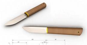
From the tool you will need a set of screwdrivers, a knife, wire cutters, a stripper for stripping insulation (optional) and a multimeter. And you may also need a PV-1 mounting wire with a cross-sectional area from 0.5 to 1.5 mm², which is available in this range of 4 types: 0.5 mm², 0.75 mm², 1 mm² and 1.5 mm². If an aluminum wire was used in the lamp, then it is better to immediately change it to copper.
It happens that they are used in lamps, but with copper plating. When stripping, the illusion of a copper wire appears, and the wire is white on the cut. It is better to get rid of such "hybrids" immediately.
| Image | Process description |
|---|---|
 | The luminaire is to be upgraded to 4 T8 lamps of 18 W each. It has 2 electromagnetic chokes, 2 capacitors and 4 starters. |
 | Instead, OSRAM QTZ8 4X18 / 220-240 VS20 electronic ballasts will be installed, which does not need either starters or capacitors. |
 | The luminaire is turned off, then the absence of a phase at the input terminal and on the housing is checked with a screwdriver-indicator, the input wires are disconnected, the luminaire is dismantled and placed on the table for ease of work with it. |
 | The front panel is dismantled from the lamp and all fluorescent lamps are removed. |
 | The input screw terminal is removed from its seat and all wires are removed from it. |
 | Electromagnetic chokes and capacitors are dismantled. |
 | The starter socket is removed. This is done very simply, as it is attached to the lamp body with plastic latches. |
 | The wires going to the starter are cut off near it. The same operations are performed with all starters. |
 | The location of the electronic ballast is selected. It is better if it is on the edge of the lamp, so that all the wires leading to the ballast can be drawn near the sides, so they will be less noticeable. Then, according to the connection diagram shown on the electronic ballast case, the position of each lamp is “assigned”. Those on the left in the diagram in the lamp will be in the center, and those on the right will be at the edges. |
 | Each fluorescent lamp socket has terminals with two pairs of spring contacts. Each pair is connected to one of the T8 lamp sockets with G13 base. This is very convenient, because in order to make a branch, you do not need to solder or twist anything. The 9 mm stripped wire is simply inserted into the terminal until it stops, where it is clamped by a spring contact. |
 | The wiring is carried out according to the circuit diagram shown on the electronic ballast. Tags from pieces of masking tape are glued to those ends of the wires that will be connected to the ballast and the terminal number is written on them. This will avoid confusion. |
 | After the wiring is completed, the electronic ballast is placed close to that place. Where it will be installed and all numbered wires are connected to the appropriate terminals. To do this, the contact mechanism is pressed with a screwdriver, and then the wire stripped by 9 mm is inserted into the terminal hole until it stops. The contact mechanism is released and the reliability of the wire connection is checked. |
 | Input terminals L, N, PE (phase, zero working, ground) are connected by wires to the input screw terminal of the lamp. |
 | After all the wires are connected to the electronic ballast, it is put into place and fixed with screws to the housing, which has special holes. If necessary, a hole can be drilled. |
 | Laid wires in the luminaire are grouped and placed as close to the edge as possible. There may be stamped antennae in the lamp body. If necessary, you can use plastic ties to organize the wires. |
 | After checking all the connections, the luminaire is given a test run on the table and, if successful, is mounted in its regular place. |
Readers have probably noticed that the installation of electronic ballast is a simple undertaking that does not require the participation of a highly qualified electrician. We can say that anyone can do it. In order not to make a mistake when connecting, we suggest drawing a diagram by hand, and then, after connecting some contacts in the lamp, mark this in your drawing. Checked - helps.

All modern fixtures are equipped so that they do not require a soldering iron for installation, there is no need to twist. All connections must be in terminals only. If the wire remaining from the old connection scheme is not enough, then in no case should you twist or solder. It is better to change this section to a solid wire. 1 meter of excellent mounting wire PV-1 with a core of 1 mm² costs 7 rubles. Connecting to the terminal takes a few seconds, and soldering already takes tens of minutes.
Video: Replacing two electromagnetic ballasts with one electronic
Repair of a faulty electronic ballast
An electronic ballast is a wonderful device that takes great care of a fluorescent lamp, but, unfortunately, cannot sometimes save itself. In this respect, the electromagnetic ballast is much more reliable; in order to “burn” it, you need to “try” very hard. Diagnosing a malfunction of an electronic ballast is quite difficult for a person unfamiliar with electronics, but, nevertheless, we will give some tips.
If nothing happens when you turn on the lamp with an electronic ballast, then you should try to change the lamp, maybe it's in it. To do this, you must have a known-good lamp, which must be inserted into the lamp sockets and try to start. If nothing happens again, then your attention should already be switched to the electronic ballast, since apart from it and the lamps there is nothing in the lamp. If there is no working lamp at hand, then you can check the integrity of the spirals in the dialing mode. If they are intact and the lamp bulb is intact, then most likely it is in good condition, unless a strong blackening of the phosphor layer is observed near the cathodes.

Electronics is the science of contacts. That's what the experts say. And before you "climb" into a complex ballast device, you need to ring all the electrical connections in the lamp, which, of course, must be disconnected from the network. It is also useful to ring the connections with the lamp inserted. To make sure that the pins of its base make contact with the cartridge. If these actions did not reveal anything "criminal", then it's time to look at the "inner world" of electronic ballast.
The electronic ballast must be removed from the housing by first disconnecting the connectors or removing the wires from the terminals. If the wires are not marked, then before disconnecting them, they must be marked in some way. The easiest is to stick strips of masking tape with the terminal number on the wire. After that, the ballast can be dismantled from the luminaire body.
An external examination of the electronic ballast can also tell a lot. If there was a strong thermal effect, then it will certainly leave traces. You can note exactly where there was a strong heating, so that later you can see which elements of the circuit could provoke it.

After opening the ballast case, carefully inspect the board. It happens that you don’t even need to inspect anything, since most of the elements are black, with obvious signs of overheating. Repair of such an electronic ballast will not be economically feasible, therefore, after soldering the entire elements (if any), the board can be thrown away.

The weak point of any electronic device is electrolytic capacitors, which are easily recognizable by their "barrel" appearance. If their ratings are not observed, if the quality is low, if the voltage is exceeded, if they are overheated, they can swell and even break, which occurs due to boiling of the electrolyte. Such signs clearly indicate a malfunction, so the capacitor is soldered and all neighboring elements are checked. A new capacitor should be chosen with a higher operating voltage, for example, it was 250 V, and a new one should be installed already at 400 V. Very often, dishonest manufacturers solder elements with a lower operating voltage into the electronic ballast board, which eventually leads to breakdown.

After the capacitors, it is necessary to carefully examine all other elements, which can also show their malfunction by their appearance. Usually burnt resistors “speak” very clearly about themselves - they darken, turn black like coal, and sometimes they simply break. Naturally, such parts also need to be changed, but it is better to choose the level of power dissipation one step or even two more than the nominal one.

Resistors can be called directly in the circuit without soldering them, since their main malfunction is burnout, which is tantamount to a break. Other elements - capacitors, diodes and transistors are better to be removed from the circuit before testing, and then use a special universal device for testing.

Burnt or “broken” diodes can also very often be easily seen by their characteristic darkening if they are in a plastic case. Diodes in a glass case often break into two parts or the bulb cracks. Ringing diodes is very easy. After soldering from the printed circuit board (only one “leg” is possible), a multimeter is taken and set to measure resistance or to a special mode indicated by a diode (if any). In the forward direction, the diode should conduct electricity well. To check this, the red probe of the multimeter is connected to the anode, and the black probe to the cathode (on diodes in a plastic case, the cathode has a strip). If the multimeter shows some resistance values, then the current flows. Swapping the probes in places, you need to make sure that the diode does not pass electric current in the opposite direction, its resistance is infinite. If so, then the diode is good. In all other cases, it is invalid.

One of the most "problematic" parts in electronic ballasts are transistors. They work in the most difficult conditions - they need to turn on and off large currents 40 thousand per second, which makes the transistors very hot. When they overheat, the properties of semiconductors change and a “breakdown” can occur, which will make the transistor useless. As a result, uncontrollably large currents begin to “walk” along the circuit, which simultaneously burn out other nearby elements that have the least resistance. That is, a transistor never burns out in “proud solitude”, it “pulls” another transistor and other elements along with it. In order for the transistor not to overheat, it is installed on a heat sink that dissipates heat. And in good electronic ballasts they do it.

If there are no radiators on transistors, then you can install them yourself by buying them at a radio store and screwing them with a screw through a hole in the case. In this case, between the transistor and the radiator, there must be thermal paste of the KPT 8 type, which is used for coolers of computer processors.
Externally, the transistor may not show any signs of its malfunction and appear to be absolutely “healthy”. Maybe this is so, but transistors in electronic ballasts should always be checked. They are one of the weak points. Although some sources on the Internet claim that the transistor can be checked without soldering it from the board, this is actually not the case. Consider another version of the electronic ballast circuit.

It can be seen that the transistors are literally “hung” with various elements that conduct well. This means that the continuity of transistors directly in the circuit will simply be incorrect. Therefore, our advice is that the transistors must be completely removed from the board, since in 80% of cases they will still be faulty if the electronic ballast is not working. Checking a transistor with a multimeter is as easy as shelling pears, you need to imagine it in the form of two diodes, and then check each of them.

If at least one burnt transistor is found, then both must still be changed, in any case. After the failure of one of the transistors in the circuit, including the second transistor, large currents begin to flow uncontrollably, which can cause some changes in the semiconductor crystal. And they are likely to show up in the future.
Chokes and transformers very rarely fail, but nevertheless it is worth checking them simply by ringing the windings with a multimeter. A high-voltage capacitor connected in parallel to the cathodes of the lamp requires special attention. It happens that manufacturers install a capacitor with an operating voltage of not 1200 V, but with a lower one. Given that this capacitor is involved in starting the lamp, the voltage across it can reach 700-800 V, which can cause it to breakdown. Therefore, it is imperative to check it and, in case of replacement, select a nominal operating voltage of at least 1.2 kV, and preferably 2 kV.
When checking and diagnosing malfunctions in electronic ballast, it is still better to check absolutely all elements. The only "tough" nut that cannot be checked with a multimeter is the dinistor. It is checked only on a special stand. Its breakdown is usually visible, since the flask of this element is glass. But it happens that in the absence of external signs of failure, it is he who is to blame for the "silence" of the electronic ballast. Therefore, it is better to have a new dinistor on hand, especially since the price for them is cheap.
Diagnostics and repair of electronic ballasts with integrated circuits can no longer be carried out. This requires special laboratory equipment and specialist services.
Video: Repair of electronic lamp ballast
Video: Repair of electronic ballast
Conclusion
The mass introduction of electronic ballasts into the control circuits of fluorescent lamps has improved the comfort of this type of lighting, increased lamp life, and achieved significant energy savings. With electronic ballasts, fluorescent lighting literally received a "rebirth" because, in addition to simply turning it on and off, "smart" electronics also made it possible to adjust the brightness in a very decent range.
The increased interest in electronic ballasts has unfortunately increased the activity of illegal and dishonest manufacturers who flood the market with low quality products. This greatly spoils the reputation of electronic ballasts in general, but smart people both understood before and understand now that it is better to buy one good electronic ballast for 10 years, even if you pay twice as much for it than to change cheaper every year or two. Therefore, you should trust only those manufacturers that have earned their good reputation for many decades.
Although incandescent lamps are cheap, they consume a lot of electricity, so many countries refuse to produce them (USA, Western European countries). Instead, they come with compact fluorescent fluorescent lamps (energy-saving), they are screwed into the same E27 cartridges as incandescent lamps. However, they cost 15-30 times more, but they last 6-8 times longer and consume 4 times less electricity, which determines their fate. The market is overflowing with a variety of such lamps, mostly made in China. One of these lamps, DELUX, is shown in the photo.
Its power is 26 W -220 V, and the power supply, also called electronic ballast, is located on a board measuring 48x48 mm ( fig.1) and is located in the base of this lamp.

Its radio elements are placed on the circuit board by surface mounting, without the use of CHIP elements. The circuit diagram is drawn by the author from an inspection of the circuit board and is shown in fig.2.

Note to the diagram: there is no dot on the diagram indicating the connection of the dinistor, diode D7 and the base of the EN13003A transistor
First, it is appropriate to recall the principle of ignition of fluorescent lamps, including the use of electronic ballasts. To ignite a fluorescent lamp, it is necessary to heat up its filaments and apply a voltage of 500 ... 1000 V, i.e. much higher than the mains voltage. The magnitude of the ignition voltage is directly proportional to the length of the glass bulb of the fluorescent lamp. Naturally, for short compact lamps it is less, and for long tubular lamps it is more. After ignition, the lamp sharply reduces its resistance, which means that a current limiter must be used to prevent a short circuit in the circuit. The electronic ballast circuit for a compact fluorescent lamp is a push-pull half-bridge voltage converter. First, the mains voltage is rectified to a constant voltage of 300 ... 310 V using a 2-half-wave bridge. The converter is started by a symmetrical dinistor, indicated in the diagram Z, it opens when, when the mains is turned on, the voltage at its connection points exceeds the response threshold. When opened, a pulse passes through the dinistor to the base of the lower transistor according to the circuit, and the converter starts up. Further, a push-pull half-bridge converter, the active elements of which are two n-p-n transistors, converts a constant voltage of 300 ... 310 V into a high-frequency voltage, which can significantly reduce the size of the power supply. The load of the converter and at the same time its control element is a toroidal transformer (indicated in the L1 diagram) with its three windings, of which two control windings (each with two turns) and one working (9 turns). Transistor keys open out of phase from positive pulses from the control windings. For this, the control windings are included in the bases of the transistors in antiphase (in Fig. 2, the beginning of the windings are indicated by dots). Negative voltage surges from these windings are damped by diodes D5, D7. The opening of each key causes the induction of pulses in two opposite windings, including the working winding. Alternating voltage from the working winding is supplied to the fluorescent lamp through a series circuit consisting of: L3 - lamp filament -C5 (3.3 nF 1200 V) - lamp filament - C7 (47 nF / 400 V). The values of the inductances and capacitances of this circuit are chosen so that voltage resonance occurs in it at a constant converter frequency. At resonance of voltages in a series circuit, the inductive and capacitive resistances are equal, the current strength in the circuit is maximum, and the voltage on the reactive elements L and C can significantly exceed the applied voltage. The voltage drop on C5, in this series resonant circuit, is 14 times greater than on C7, since the capacitance of C5 is 14 times less and its capacitance is 14 times greater. Therefore, before the fluorescent lamp is ignited, the maximum current in the resonant circuit heats both filaments, and the large resonant voltage across the capacitor C5 (3.3 nF / 1200 V), connected in parallel with the lamp, ignites the lamp. Pay attention to the maximum allowable voltage on the capacitors C5 = 1200 V and C7 = 400 V. These values are not chosen by chance. At resonance, the voltage across C5 reaches about 1 kV and it must withstand it. A lit lamp sharply reduces its resistance and blocks (short-circuits) capacitor C5. Capacitance C5 is removed from the resonant circuit, and the voltage resonance in the circuit stops, but the already lit lamp continues to glow, and the inductor L2 limits the current in the lit lamp with its inductance. In this case, the converter continues to operate in automatic mode, without changing its frequency from the moment it was started. The entire ignition process takes less than 1 s. It should be noted that alternating voltage is constantly applied to the fluorescent lamp. This is better than constant, as it ensures uniform wear of the emissivity of the filaments and thus increases its service life. When lamps are powered by direct current, their service life is reduced by 50%, therefore, direct voltage is not supplied to gas-discharge lamps.
Assignment of the elements of the converter.
The types of radio elements are indicated on the circuit diagram (Fig. 2).
1. EN13003A - transistor switches (for some reason, the manufacturers did not indicate them on the wiring diagram). These are bipolar high-voltage transistors of medium power, n-p-n conductivity, TO-126 case, their counterparts MJE13003 or KT8170A1 (400 V; 1.5 A; in a pulse of 3 A), KT872A (1500 V; 8 A; T26a case), but they are larger in size. In any case, it is necessary to correctly determine the BCE outputs, since different manufacturers may have different sequences, even for the same analogue.
2. Toroidal ferrite transformer, designated by the manufacturer L1, ring dimensions 11x6x4.5, probable magnetic permeability 2000, has 3 windings, two of them with 2 turns and one with 9 turns.
3. All diodes D1-D7 are of the same type 1N4007 (1000 V, 1 A), of which diodes D1-D4 are a rectifier bridge, D5, D7 - dampen negative control pulse surges, and D6 - separate power supplies.
4. The R1SZ chain provides a delay in the start of the converter in order to “soft start” and prevent an inrush current.
5. Symmetrical dinistor Z type DB3 Uzs.max=32 V; Uoc=5 V; Uneotp.and.max=5 V) ensures the initial start of the converter.
6. R3, R4, R5, R6 - limiting resistors.
7. C2, R2 - damper elements designed to dampen the transistor switch emissions at the moment of its closing.
8. Inductor L1 consists of two W-shaped ferrite halves glued together. Initially, the inductor participates in voltage resonance (together with C5 and C7) to ignite the lamp, and after ignition, it extinguishes the current in the fluorescent lamp circuit with its inductance, since the lit lamp sharply reduces its resistance.
9. C5 (3.3 nF / 1200 V), C7 (47 nF / 400 V) - capacitors in the fluorescent lamp circuit involved in its ignition (through voltage resonance), and after ignition C7 maintains the glow.
10. C1 - smoothing electrolytic capacitor.
11. The inductor with a ferrite core L4 and the capacitor C6 constitute a surge filter that does not pass the transducer's impulse noise into the mains supply.
12. F1 is a 1A mini fuse in a glass case, located off the circuit board.
Repair.
Before repairing the electronic ballast, it is necessary to “get” to its circuit board, for this it is enough to separate the two components of the base with a knife. When repairing a board under voltage, be careful, as its radio elements are under phase voltage!
Burnout (break) of incandescent spirals of a fluorescent lamp, while the electronic ballast remains intact. This is a typical error. It is impossible to restore the spiral, and glass fluorescent bulbs for such lamps are not sold separately. What is the way out? Or adapt a working ballast to a 20-watt lamp with a straight glass lamp, instead of its "native" choke (the lamp will work more reliably and without hum) or use the board elements as spare parts. Hence the recommendation: buy the same type of compact fluorescent lamps - it will be easier to repair.
Cracks in the soldering of the circuit board. The reason for their appearance is periodic heating and subsequent, after turning off, cooling of the place of soldering. The place of soldering is heated from elements that are heated (spirals of a fluorescent lamp, transistor switches). Such cracks may appear after several years of operation, i.e. after repeated heating and cooling of the soldering point. The malfunction is eliminated by re-soldering the crack.
Damage to individual radio elements. Individual radio elements can be damaged both from solder cracks and from power surges in the mains. Although there is a fuse in the circuit, it will not protect the radio elements from voltage surges, as a varistor could do. The fuse will burn out from breakdowns of radio elements. Of course, the weakest point of all the radio elements of this device are transistors.
Radioamator №1, 2009
List of radio elements
| Designation | Type | Denomination | Quantity | Note | Shop | My notepad |
|---|---|---|---|---|---|---|
| bipolar transistor | MJE13003A | 2 | N13003A, KT8170A1, KT872A | To notepad | ||
| D1-D7 | rectifier diode | 1N4007 | 7 | To notepad | ||
| Z | Dinistor | 1 | To notepad | |||
| C1 | electrolytic capacitor | 100uF 400V | 1 | To notepad | ||
| C2, C3 | Capacitor | 27 nF 100 V | 2 | To notepad | ||
| C5 | Capacitor | 3.3nF 1200V | 1 | To notepad | ||
| C6 | Capacitor | 0.1uF 400V | 1 | To notepad | ||
| C7 | Capacitor | 47 nF 400 V | 1 | To notepad | ||
| R1, R2 | Resistor | 1.0 ohm | 2 |
When the ballast for fluorescent lamps (LL) fails, the lighting fixture stops functioning correctly. To return it to normal mode can only be a quick replacement of the damaged element with a serviceable one.
You can buy the part in a specialized store, the main thing is to choose the correct modification module. Our article is devoted to the solution of this issue.
We will tell you what a ballast is, what tasks it performs in the operation of a fluorescent lamp. We will give a detailed classification, as well as describe the specifics of the functioning and application of different modules. We will help you choose the right ballast, taking into account the parameters of the lamp and the manufacturer of the control device.
A fluorescent lamp is a practical and economical module designed to organize lighting systems in domestic, industrial and technical premises.
The only difficulty is that it is not possible to directly connect the device to centralized power supply communications.
This is due to the fact that the creation of a stable activating discharge and the subsequent limitation of the increasing current require the organization of some specific physical conditions. It is these problems that the installation of a ballast device solves.
What is ballast
The ballast is a device that regulates starting functions and connects fluorescent lighting devices to electrical communications.
It is used to maintain the correct mode of operation and effectively limit the operating current.
It acquires increased relevance when there is insufficient electrical load in the network and there is no necessary limitation on current consumption.
The general principle of the element
Inside the fluorescent lamps is an electrically conductive gaseous medium with negative resistance. This is manifested in the fact that with an increase in current between the electrodes, the voltage decreases significantly.
Compensates for this moment and ensures the correct operation of the lighting device, a ballast connected to the control system.
When a large amount of current is supplied to any luminescent device, it can fail. To prevent this from happening, a ballast is included in the design of the lamp, which acts as a converter.
It also increases the overall voltage for a short period and helps the luminescents to light up when there is not enough resource for this in the central network. Additional functions of the module vary depending on its design features and type of execution.
Varieties and characteristics of ballasts
Today, electromagnetic and electronic ballast devices are the most widespread. They work reliably and provide long-term correct functioning and comfortable operation of fluorescent lamps of all types. They have the same general principle of operation, but differ somewhat in individual capabilities.
Features of electromagnetic products
Electromagnetic type ballasts are used for lamps connected to the central electrical network using a starter.
The supply of voltage in this embodiment is accompanied by a discharge, followed by intense heating and closing of the bimetallic electrode elements.

Electromagnetic ballast differs from electronic one even in appearance. The first has a more massive, high design, and the second is an elongated thin board, on which all the working elements are located.
At the moment when the starter electrodes close, the operating current increases sharply. This is due to the limitation of the maximum resistance of the choke coil.
After the starter has completely cooled down, the bimetallic electrodes open.

If the starter fails in the design of the electromagnetic ballast, a false start appears in the operation of the luminescent. At the same time, at the moment of switching on and immediately before full ignition, the lamp flashes 3-4 times and only then starts to burn. This leads to the consumption of excess energy and significantly reduces the overall working life of the light source.
When the luminescent circuit is opened by the starter, an active high voltage pulse is immediately formed in the induction coil and the lighting device is ignited.
The advantages of the device include:
- high level of reliability, proven by time;
- operational comfort of the electromagnetic module;
- ease of assembly;
- affordable price, making the product attractive to manufacturers of light sources and consumers.
In addition to positive aspects, users note an extensive list of disadvantages that spoil the overall impression of the device.
Among them are such positions as:
- the presence of a strobing effect, in which the lamp flickers at a frequency of 50 Hz and causes an increase in the level of fatigue in a person - this significantly reduces performance, especially when the lighting device is located in a work or study room;
- a longer time required to start the lighting device - from 2-3 seconds at the beginning and up to 5-8 by the middle to the end of the operational period;
- audible specific hum;
- increased electricity consumption, resulting in an inevitable increase in utility bills;
- low reliability;
- cumbersome design and its significant weight.
When buying, all these conditions must be taken into account in order to understand what the operation of a household lighting system equipped with fluorescents will cost in the future.
Electronic ballast modules
The electronic type ballast is used for the same purposes as the electromagnetic module. However, structurally and according to the principle of performing their duties, these devices differ significantly from each other.

Cheap electronic ballast, has a simple self-oscillating circuit with a transformer and a basic output stage operating on bipolar transistors. A big minus of these devices is the lack of protection against abnormal operating conditions.
Widespread popularity came to products in the early 90s. At this time, they began to be used in combination with a variety of light sources.
Initially, the manufacturers compensated for the high cost compared to electromagnetic products with the good efficiency of the devices and other useful characteristics and properties.
The use of electronic ballasts made it possible to reduce the total consumption of electrical energy by 20-30%, while maintaining full saturation, power and strength of the light flux.
This effect was achieved by increasing the base light output of the lamp itself at an increased frequency and a significantly higher efficiency of electronic modules compared to electromagnetic ones.

The most vulnerable elements of the electronic ballast are the fuse (1), capacitor (2) and transistors (3). It is they who usually fail for various objective reasons and lead the lamp to an inoperative state.
The soft start and gentle operating mode made it possible to extend the life of the luminescents by almost half, thus reducing the overall operating costs of the lighting system. Lamps needed to be changed much less often, and the need for starters disappeared altogether.
In addition, with the help of electronic ballasts, it was possible to get rid of working background noise and pronounced annoying flicker, while simultaneously achieving stable and uniform illumination of the premises even with mains voltage fluctuations in the range of 200-250 V.

To prevent the fluorescent lamp from buzzing and flickering, it is necessary to feed it only with high-frequency current of 20 kHz or more. To implement this task, the switching circuit must include a rectifier, a high-voltage RF generator and a ballast that plays the role of a switching power supply
Additionally, it became possible to control the brightness of the lamp, adjusting the light flux to the individual desires and needs of the user.
Among the main advantages of the products, the following criteria stood out:
- light weight and compact design;
- almost instantaneous, very smooth switching on, which does not exert excessive load on the fluorescent lamp;
- the complete absence of blinking visible to the eye and a distinguishable noise effect;
- high operating power factor of 0.95;
- direct saving of electric current in the amount of 22% - the electronic module practically does not heat up compared to the electromagnetic one and does not consume extra resources;
- additional protection built into the unit to ensure a high level of fire safety and reduce potential risks arising during operation;
- significantly increased service life of luminescents;
- a light flux with a good color density, without drops, even with prolonged burning, does not provoke eye fatigue of people in the room;
- high efficiency of the functioning of the lighting device at negative temperature indicators;
- the ability of the ballast to automatically adjust to the parameters of the lamp, thus creating the optimal mode of operation for itself and the lighting fixture.
Some manufacturers complete their electronic ballasts with a special fuse. It protects devices from power surges, fluctuations in the central network and erroneous activation of a lamp without a lamp.

Today, labor protection authorities recommend that, in order to improve working conditions and increase productivity, equip fluorescent lamps installed in office premises with electronic rather than electromagnetic starting devices.
Of the minuses of electronic products, only the cost is usually mentioned, which is much higher compared to electromagnetic modules. However, this may only matter at the time of purchase.
In the future, in the process of intensive operation, the electronic ballast will fully work out its price and even begin to bring benefits, seriously saving the electrical resource and removing part of the load from the light source.
Ballasts for compact lamps
Fluorescent lamps are devices similar to traditional incandescent lamps with an E14 and E27 threaded base.
They can be placed in modern and rare chandeliers, sconces, floor lamps and other lighting fixtures.

Due to the design features of compact fluorescents, increased requirements are imposed on the electronic "stuffing". Brands always take them into account in production, and unknown manufacturers, in order to reduce the cost, change many elements to simpler ones. This significantly reduces the efficiency and service life of the module.
Devices of this class are completed, as a rule, with a progressive electronic ballast, which is built directly into the internal structure and is usually located on the lamp product board.
What to look for when choosing
When choosing a ballast for a fluorescent lamp, it is first necessary to pay attention to such a parameter as the power of the module.
It must fully match the power of the lighting device, otherwise the lamp simply will not be able to fully function and produce a light flux in the required mode.

It is strictly forbidden to connect the ballast to the network without load. The device may burn out immediately and you will have to repair it or buy a new one.
True, such devices are considered obsolete, have bulky dimensions and consume additional energy. This significantly reduces their attractiveness, even despite the affordable initial price.

To check the health of the electronic ballast, a special measuring device is useful - a pocket oscilloscope
Electronic devices are much more expensive. This point is especially true for products produced by cool branded manufacturers. But their price is more than offset by energy efficiency, practicality, flawless assembly and a high level of overall quality of devices.
Selection of ballast by manufacturer
The manufacturing plant is another significant criterion when buying. You should not focus solely on the price and purchase the cheapest model of all that are offered in the store.
Features of branded ballasts
An unnamed Chinese-made product can fail very quickly and lead to subsequent problems with the operation of the light bulb itself and even the lamp.

Brand manufacturers complete ballasts with high-quality, wear-resistant parts that ensure the correct operation of the module throughout the entire operational period.
It is better to give preference to brands with a reliable reputation, which have proven themselves for a long time in the market of lighting equipment and related items.
Such devices will reliably work out the entire prescribed period, ensuring the full functioning of the luminescent in any lighting device.
The ballast products, produced by the enterprises of popular brands specializing in the manufacture of electrical equipment and related components, have a strong and durable outer casing made of a heat-resistant, non-deforming plastic compound.
The IP2 marking on the products indicates that the device has a good level of overall protection and is protected from foreign parts larger than 12.5 mm entering the box.
The operation of the device is comfortable and absolutely safe. The design completely eliminates the possibility of user contact with conductive elements.

Ballast modules marked IP2 are reliable, practical and convenient for domestic use, however, they are vulnerable to dust penetration. Because of this small minus, it is not advisable to put them in lamps illuminating dusty work areas.
The normal temperature range for effective and continuous operation of the device is quite wide.
Branded ballasts do their job well in frosts down to -20°C and feel great on hot days when the air heats up to +40°C.
The best manufacturers of electromagnetic devices
Electromagnetic ballast devices manufactured under the brand name are very popular with customers. E.Next.
This is due to the fact that the company offers truly high-quality, reliable and progressive modules, made at the highest level in strict accordance with the requirements for equipment of this class.

In addition to warranties and maintenance, E.Next offers customers custom technical support through call centers. By calling there, the consumer can ask the operator a question of any complexity and receive a professional, understandable answer within a few minutes.
The company gives a company guarantee for all products and offers customers high-quality service at all stages of cooperation.
Equally in demand are electromagnetic ballasts created by a well-known and respected European manufacturer of electrical equipment and related elements - the company Philips.
Products of this brand are considered one of the highest quality, reliable and efficient.

Electromagnetic modules from Philips are presented on the market in the widest range. Finding the right option for a lamp of any configuration is not difficult
Philips ballasts help save energy and neutralize the load that occurs during the operation of fluorescent lamps.
Actual electronic modules
Products of electronic type belong to the modern type of equipment and, in addition to traditional ones, also have additional functions. In this segment, the leading positions are occupied by products from a German company Osram.
Their cost is slightly higher than that of Chinese or domestic counterparts, but significantly lower compared to competitors such as Philips And Vossloh Schwabe.

Osram electronic ballasts have a number of advantages. They have a neat shape and modest dimensions, can operate in a temperature range of -15 ... +50 ° C and reliably serve for 100,000 hours.
Among the budget branded modules, electronic ballasts stand out clearly from competitors Horos.
Despite the loyal cost, these items demonstrate high working efficiency and a good level of efficiency, eliminate the ignition delay, reduce energy consumption to a minimum and increase the light output of the lamp itself.
With the help of these tools, annoying flickering in fluorescent lamps can be eliminated and lighting fixtures can be made as convenient and comfortable as possible.
A young, promisingly developing company does not lag behind the venerable old-timers of the market Feron. It offers users European-level products at a very small, reasonable price.

Feron ballasts are carefully made. All details have certificates of conformity. The outer case, made of plastic, is an elongated flat rectangle. The product weighs little and is easily mounted in fluorescent light sources of any configuration.
Ballast-type devices from Feron protect the lamps from unexpected electromechanical interference and voltage drops, eliminate eye-irritating flicker and help save more than 30% of electrical energy.
Feron's ballast-controlled luminescent turns on/off instantly. There is no background sound effect during operation. The lighting is soft, even and creates a pleasant, calm atmosphere around.
Conclusions and useful video on the topic
How does an electronic device work in a fluorescent lamp. Detailed description of the device and the principle of operation of the product:
What is the difference between electromagnetic and electronic ballasts. Features of each of the modules and the specific nuances of their use in household lighting fixtures:
Features of the operation of luminaires equipped with different types of ballasts. Which elements are more effective and why. Practical recommendations and useful tips from the personal experience of the master:
To choose the right ballast for household fluorescent lamps, you need to know how this element works and what function it performs. Having such information, as well as understanding the varieties of the device, it will be possible to acquire the desired modification without any difficulties.
The cost of the module depends on the manufacturer, but even branded products have a completely loyal price and do not cause damage to the budget of the average consumer.
Do you have experience in selecting and replacing the ballast in a fluorescent lamp? Please tell readers which module you prefer and if you are happy with the purchase. Comment on the post and participate in discussions. The feedback block is located below.