How to make a tank of paper instructions.
The creation of paper tanks may interest not only boys, but also girls. Firstly, such figures will be great toys for them. Secondly, the very process of creating a figurine causes an unprecedented interest in children, develops motor skills. And thirdly, many parents during the process of forming such figures tell children about the great wars and their features, attracting kids to the history of their state. So, how to make a tank of paper and where to find the layout and drawing?
The creation of paper tanks may interest not only boys but also girls
The T 34 corresponding to a real machine can be glued from paper using ready-made reamers. To do this, you will first need to print the required scan on thick paper. Then you should cut out all the painted parts.

 To make T 34 from a sweep, you must follow the instructions:
- Fold lines should be found on cut elements. A ruler is applied to each of them, and then the free edge of the paper is lifted and ironed. This results in an even fold.
- After all the bends are indicated, you can proceed to gluing the model.
- The first step is to glue the main body of the tank. To do this, it is advisable to use clear acrylic adhesive or quick-drying PVA.
- Then all minor details are glued to the body.
- Next, you can move on to the gun. First of all, its base is glued together, and only after that the gun is supplemented with secondary elements. The finished model is glued to the main body of the combat vehicle.
- After that, the caterpillars gather. First, inner circles are made, and only after that they are framed by a single caterpillar strip. Ready-made tracks are mounted on the sides of the body.


It is worth considering that there are various scans of the T 34 tank, which may differ from each other in color and conditionality. If it was possible to print only the black and white version of the machine, before assembly it should be painted using acrylic paints. Such processing of cardboard will allow you to purchase a future toy type of tank with a natural coating.
Gallery: paper tank (25 photos)


Tank IS 7 from paper
To make this tank, you should also use a ready-made scan.


- All scan elements are cut with the help of a clerical knife.
- Then, using a ruler, bends are made at all the places marked for these purposes.
- The supporting structure for the housing is made. It is made of two rectangles mounted parallel to each other and fixed by 3 transverse bars located at an equal distance from each other.
- A body with a circle cut out in it is glued to the resulting base.
- The body is glued to the sides, niches for the tracks are formed. A tank bottom is being formed.
- The basis for the cannon mount is being made. It is done in the same way as for the case. A manufactured tower is installed on the hull. A machine gun and additional elements are glued to the tower.
- Then the tracks are made: medium - smooth, rear - with teeth.
- The tracks are glued to the bottom of the main body, fastened with a caterpillar.
This model is notable for rather high assembly complexity, therefore, when creating it with children, it is necessary to provide them with extensive assistance. When assembling it with children, you can abandon several small parts, thereby simplifying the bonding process.
How to make a T 90 tank from paper?
T 90 can be made using the origami technique. To do this, you only need paper: sheet A4 and a small piece of paper for notes.

T 90 can be made using the origami technique
How to do:
- First, sheet A4 is folded. First of all, he leans in half lengthwise.
- The perpendicular sides of the sheet are bent, connecting with each other. First, the short side is applied to the bottom long, and then to the top. Similar manipulations should be performed on both sides of the sheet.
- The sheet is turned over. The corners of the short side are bent to the ends of the crosses formed from the fold line.
- The sheet is turned over and bent along the received lines, forming the basic shape of a double triangle.
- The long sides fold to the middle so that the resulting double triangles are on top of them. The result is a double arrow.
- Freshly bent edges bend to the outside of the rectangle.
- The lateral corners of one of the triangles are bent to the top.
- The workpiece is turned over and conditionally divided into 3 parts so that in the end the top of the folded triangle touches the middle of the base of the opened.
- The free corners of the triangle bend inward.
- "Ears" from the previously bent triangle are set into the resulting pockets.
- The result is a tower.
- A small sheet of paper is folded into a cylindrical barrel using a knitting needle or cooking skewer.
- The barrel is inserted into the hole in the tower and glued.
The figure assembled in this way can be decorated using thick paints, felt-tip pens or pencils.
How to make a tank from origami modules?
To create tanks, you can use the assembly scheme, which offers modular origami. To begin with, the assembler will need to prepare 1688 triangular modules.
How to assemble:
- The first thing is going to the tower. Her first and second row are closed in a circle. Each row consists of 30 modules.
- The workpiece is turned inside out, complemented by a third layer consisting of a similar number of elements. In this way, the tower is built up to 8 layers.
- The ninth row is assembled from 30 modules, but they should be installed backwards.
- Next, you need to proceed to the tracks. A chain of 4 rows is made, each of which has 50 modules.
- On the fifth row, 46 elements are used. The reduction should be carried out in places where the track is bent.
- 7 row consists of 46 elements installed back to front.
- The same pattern is used to create a second track.
- For each track, 3 wheels are made. To do this, a circle of 2 rows is made, in each of which 10 modules are involved. The figure is turned inside out and complemented by 5 rows.
- The wheels are placed inside the track. These elements are connected by a middle bar made of 34 rows: 1 to 5 modules, 2 to 4 elements. Next, the rows alternate.
- A slightly bent part is inserted between the tracks.
- A tower is placed on top.
- The gun is made of 20 rows, the width of which alternates: 1 row - 2 elements, 2 row - 1. The last three rows increase to 4, 3 and 4 elements.
- A machine gun is inserted into the tower.

Today you can download free drawings of a paper model of the T-34 tank at the end of our article.
The main difference between these tank drawings are prefabricated tracks. Since they are made from individual links, you can give the tracks of the paper model of the tank any shape. Such a paper model can be put on a diorama or in a cabinet.
To assemble the paper model of the tank, you will only need a paper knife, paper and glue. Well, another color printer for printing drawings of a paper model. The assembly of this paper model is quite simple, only requires accuracy when assembling small parts.
The T-34 tank has a decisive role in all the major battles of the Red Army during the Great Patriotic War. Universal in nature, it was successfully used both for direct support of infantry and for high-speed maneuverable combat operations.
During World War II, the “thirty-four” became the basis of the tank fleet of the Red Army. More than 54,000 T-34 tanks were produced at the country's seven largest factories - more than 70% of all types of tanks produced. The T-34 tank turned out to be the best suited for mass production, it was quite simple to manufacture, operate and repair, had a relatively low cost. An important feature of the “thirty-four” is the simplicity of mastering the combat vehicle by its crew.
Today, T-34 tanks stand on pedestals in the cities and villages of many countries of the world, decorate the collections of the most prestigious military-historical and technical museums.
By the way, there is a very interesting film on plasticine animation about the Soviet T-34 tank.
This film is about the T-34 tank in an ironic way tells the whole story of design modernization. I recommend to view!
Download free drawings of a paper model of the T-34 tank can
Presentation description for individual slides:
1 slide
Description of the slide:
Municipal budgetary educational institution “Verkhovna Secondary School No. 1” Museum model of the T-34 tank Completed by: student of the 11th grade Shakhov Alexander Head: technology teacher Martynov Oleg Ivanovich TOP 2014
2 slide
3 slide
Description of the slide:
SELECTION AND JUSTIFICATION OF THE PROJECT TOPIC I study in the 11th grade, at the school museum of local history, I study in the study group “Local history”, I also like craftsmanship, and am fond of technology. Our museum has a Hall of Military Glory. There are documents telling about the battles for the liberation of our village from the Nazis, there are some examples of weapons of the Red Army and Nazi Germany. There are models - copies of the main combat aircraft made by members of the aircraft model circle. Last year, I also made a model of the aircraft of the LA-5 fighter and presented it to the museum. In 2015, our country celebrates the 70th anniversary of Victory in the Great Patriotic War. In this regard, and in consultation with the head of the museum, I decided to take the theme of my project for the production of a mock-up copy of some type of armored vehicles and replenish them with the museum's exposition. one
4 slide
Description of the slide:
GOALS AND OBJECTIVES Purpose: To create an original, useful product for the school. Tasks: 1. Know and carry out modeling techniques. 2. Learn how to mentally represent the subject and graphically express it in the form of a technical drawing and drawing. 3. Work with technological documentation. 4. Know and correctly carry out work methods on the machines. 5. Reasonably express your opinion and make the right decision when designing. 6. Realistically evaluate your knowledge and skills. 2
5 slide
Description of the slide:
SELECTION OF PRODUCT OPTIONS Having examined several types of tanks that were in service with the Red Army during the years of V.O.V., I opted for the legendary thirty-four tank T-34. In my opinion, it looks very beautiful and will be easier to manufacture than the rest. 3
6 slide
Description of the slide:
7 slide
Description of the slide:
The Biography of the thirty-quarter began in October 1937 when the tank design bureau of the Kharkov plant received an order from the Main Auto Armored Directorate of the Red Army to design a new machine that could replace a BT tank in service in the future. Work began on the creation of a tank with anti-shell armor. The design of a wheeled - tracked vehicle with 30 mm armor and a 45 mm gun was carried out at the Kharkov plant in the design department, headed by M. Koshkin. After a year and a half, the USSR Defense Committee was presented with the design of the caterpillar tank, named A-32. On December 19, 1939, the country's government decided to create an improved version of the A-32 tank - the T-34 medium tank, which later became one of the most famous in the history of world tank building. The manufacture of the first two prototype thirty-four began in January 1940. And already at the end of February, the tanks went on their own to Moscow. After the cars were shown in the Kremlin, field tests began. T-34 forced to overcome the most difficult obstacles, to perform dizzying maneuvers. Direct fire was fired at them with high-explosive and armor-piercing shells. In June 1940, the Politburo of the Central Committee of the All-Union Communist Party of Bolsheviks adopted a decision on the deployment of the production of T-34 tanks. By January 1, 1941, the Kharkov plant managed to produce 115 of the 600 cars ordered. 5
8 slide
Description of the slide:
In the spring of 1941, designers and technologists launched a tremendous amount of work to improve and simplify the production of thirty-four. This primarily concerned the manufacture of towers. At the first cars, they were welded from rolled armored plates. This process was complex, laborious, expensive. In an effort to simplify it, the engineers developed a new technology that provided for the welding of a tower with an armor thickness of 52 mm from just two cast elements. By the beginning of World War II, there were already 1,225 T-34 tanks in the Red Army, 967 of them in the western districts. The Stalingrad Tractor and the Krasnoye Sormovo plant in Gorky joined in production. Both opponents and our allies in the Second World War failed to create a tank that surpasses the legendary thirty-four. The T-34 was reliable, easy to manufacture, operate and repair, and easy to learn. Thirty-fours bore the brunt of the fight against fascist armored hordes from 1941 to 1945. 6
9 slide
Description of the slide:
10 slide
Description of the slide:
DRAWINGS OF THE TANK T-34 -76 I found the drawings of the tank in the magazines “Modelist-constructor”. Using an epidemioscope, I enlarged them to the scale I needed 1:10, then developed and cut out corps, towers, and fuel tanks from cardboard and compiled technological maps for making the main parts of the tank. 8
11 slide
Description of the slide:
12 slide
Description of the slide:
SELECTION OF MATERIALS For the manufacture of my product, I used affordable and cheap structural materials, wood and metals. For the case, I chose a galvanized sheet, 0.2 mm thick. She bends well, solders, is processed. The metal case allows fastening and performing on it the smallest details with great reliability by the method of soldering and surfacing of tin with further processing. The tank turret, track rollers and final drive bodies are made of birch wood. Birch has wood with a brownish tint wood, solid, dense. It is well processed, sharpened. Steel St-3 is a cheap, affordable structural material. Durable, well processed, sharpened, soldered. The gun barrel, front guides and rear drive wheels are machined from a steel bar. Copper is a soft metal of orange - red color. Easy to process, bend, solder. Copper tubes and wire were used for the manufacture of exhaust pipes, machine guns, brackets. Tin is a soft, heavy metal, silvery color, does not oxidize, and easily melts. It was used as solder and for casting tracks of caterpillar chains. 10
13 slide
Description of the slide:
Epoxy universal adhesive. It is used for bonding metals, their alloys, glass, wood. Primer GF - 021. It was used to cover the product after assembly before painting. PF-115 alkyd enamels of various colors. Soldering acid is a flux for soldering metals. eleven
14 slide
Description of the slide:
SELECTION OF TOOLS AND EQUIPMENT 1. TV-6 lathe 2. STD-120 lathe 3. Drilling machine 4. Drill 5. File set 6. File set 7. File set 8. Drill 9. Jigsaw 10. Planer 11. Line 12 .Drawing 13. Kerner 14. Caliper 15. Compass 16. Pencil 17. Awl 18. Knife 19. Hammer 20. Set of brushes 21. Abrasive skin 22. Soldering iron 23. Compressor 24. Spray gun 12
15 slide
Description of the slide:
TECHNOLOGICAL MAPS According to the drawings, with the help of a technology teacher, I developed and drafted technological maps for the manufacture of the main parts and parts of the T-34 -75 tank. 13
16 slide
Description of the slide:
MANUFACTURE OF THE TOP OF THE TANK HOUSING No. Name Quantity Scale Material 1 Upper part of the body 1 1:10 Tin Production plan No. 1 14
17 slide
Description of the slide:
The sequence of technological operations Graphic image Tools Equipment materials 1. Cut the workpiece of the required size Ruler Scriber Scissors for Metal Tin 2. Draw the part contours on the workpiece Scriber Kerner template 3. Cut the scan of the part. Scissors for Metal File Grind out burrs 4. Drill marked holes Drilling sled Hand vise Drill 5. Bend the reamer along the fold lines. Solder corners. Scissors for metal Bench vice Mandrel Soldering iron 15
18 slide
Description of the slide:
19 slide
Description of the slide:
The sequence of technological operations Graphic image Tools equipment materials 1. Select the blank of the required size Ruler Pencil Hacksaw Timber 2. Mark the contours of the bottom of the tower using the template Template 3. Mark the contours of the top of the tower with the template Template Pencil 4. Drill a hole for installing the gun barrel Bench vice Drill Drill 5. Process the part according to the marking. To clean surfaces. Planer Rasp Emery cloth 17
20 slide
Description of the slide:
MANUFACTURE OF THE SIDE WALL OF THE LOWER PART OF THE TANK HOUSING No. Name Quantity Scale Material 1 Side wall 2 1: 10 Tin Flow sheet No. 3 18
21 slide
Description of the slide:
The sequence of technological operations Graphic image Tools Equipment Materials 1. Cut the workpiece of the desired size. Ruler Scriber Scissors for metal Sheet 2. Draw the contours of the part according to the template. Template Scriber Kerner 3. Cut the part. Strip the burrs. Scissors for metal File 4. Drill holes Drilling machine Manual vise Drill 19
22 slide
Description of the slide:
The manufacture of the engine cover No. Name Quantity Scale Material 1 Engine cover 1 1:10 Tin Flow sheet No. 4 20
23 slide
Description of the slide:
The sequence of technological operations The graphic image Tools Equipment Materials 1. Cut the workpiece of the required size Line Pencil Scissors for metal Tin 2. Draw the outline of the part on the template Template Scriber Kerner 3. Cut the part. Strip the burrs. Metal scissors File 4. Drill the marked holes. Drilling machine Manual vise Drill 5. Cut down the engine ventilation windows. Strip the burrs. Hammer Chisel File 21
24 slide
Description of the slide:
The sequence of technological operations Graphic image Tools Equipment Materials 6. Bend the part along the fold lines. Bench vise Mandrel Hammer Pliers 7. Solder corners 8. Close the engine ventilation windows with a mesh. Soldering iron Soldering acid Solder Soldering iron Soldering acid Solder Metal mesh 9. Finish the final cleaning of the file File Emery cloth 22
25 slide
Description of the slide:
MANUFACTURE OF THE Muzzle of guns No. Name Quantity Scale material 1 Muzzle of guns 1 1: 10 Steel Technological map No. 5 23
26 slide
Description of the slide:
The sequence of technological operations Graphic image Tools Equipment Materials 1.Select the steel bar of the desired size. Ruler Hacksaw for metal Bar Bench vise 2. Fasten the workpiece in the lathe chuck. Drill hole. Lathe TV-6 Drill 3. Fix the workpiece in the lathe chuck and the tailstock cone. Lathe TV-6 Workpiece 4. Grind the workpiece to the desired size. Turning Machine TV-6 Cutter Caliper 5. Perform the final cleaning of the part. Sanding tool Emery cloth 24
27 slide
Description of the slide:
Production of a fuel tank No. Name Quantity scale Material 1 Fuel tank 3 1: 10 Tin Flow sheet No. 6 25
28 slide
Description of the slide:
The sequence of technological operations Graphic image Tools Equipment Accessories 1. Cut the workpiece of the desired size. Ruler Scriber Scissors for metal Sheet 2. Draw the contours of the part according to the template. Scriber template 3. Cut out a detail scan. Strip the burrs. Scissors for metal File 4. Bend the workpiece along the fold lines. Pliers Workpiece 5. Solder the seams of the workpiece. Soldering Iron Soldering Acid Solder 26
29 slide
Description of the slide:
MANUFACTURE OF THE SUPPLEMENT ROLLER № Name Quantity Scale Material 1 Track roller 10 1: 10 Birch Technological map No. 7 27
30 slide
Description of the slide:
The sequence of technological operations Graphic image Tools Equipment Materials 1.Select the workpiece of the required size. Ruler Pencil Hacksaw Wood 2. At the ends of the workpiece mark the centers. Touch the edges. Joiner's workbench Planer Ruler Pencil 3. Mark and make a cut at the end of the workpiece. Tilt the centers. Ruler Pencil Hacksaw Kerner Hammer 4. Fix the workpiece in a lathe. To process to the desired diameter. Lathe STD-120 Chisels vernier caliper 5. Grind spikes and chamfers. To clean surfaces. Cut off the part. Lathe STD-120 Chisels Emery cloth 28
31 slide
Description of the slide:
The sequence of technological operations Graphic image Tools Equipment Materials 6. Fasten the workpiece in a chuck with reverse cams. Lathe TV-6 Workpiece 7. Drill a hole. Lathe TV-6 Drill 8. Make grooves at the ends of the workpiece. TV-6 lathe Cutter Caliper 9. Final cleaning of the part TV-6 lathe Emery cloth 29
32 slide
Description of the slide:
MANUFACTURE OF THE GUIDE WHEEL No. Name Quantity Scale Material 1 Guide wheel 2 1: 10 Steel Technological map No. 8 30
33 slide
Description of the slide:
The sequence of technological operations Graphic image Tools Equipment Materials 1.Select the workpiece of the required size. Ruler Caliper Hacksaw for metal Steel bar 2. Fix the workpiece in the lathe chuck and drill to the desired diameter. Lathe TV-6 Cutter Caliper 3. Cut a tenon in the workpiece to the desired depth. Lathe TV-6 Cutter Caliper 4. Make a groove from the end face of the workpiece. Lathe TV-6 Cutter Caliper 5. Drill a hole in the workpiece. Lathe TV-6 Drill Caliper 31
34 slide
Description of the slide:
The sequence of technological operations Graphic image Tools Equipment Materials 6. Cut off the finished part. Lathe TV-6 Cutter Caliper 7. Make a groove at the end of the part. Lathe TV-6 Cutter Caliper 8. Mark and drill holes. Vernier Caliper Kerner Hammer Drilling Machine Drill Vise 32
35 slide
Description of the slide:
36 slide
Description of the slide:
Safety precautions when working on a TV-6 turning screw machine Before work: Put on work clothing, fasten sleeves, and prepare safety glasses. Firmly fix the cutter and the workpiece. Remove the cartridge key. Check the handles of the machine, take the cutter away from the workpiece. Turn on the machine and check its idling. During operation: Gently bring the cutter to the workpiece. It is forbidden: - to measure the workpiece; - remove chips, lubricate and clean the machine without turning it off; - move away from a working machine; -After turning off the machine, brake the cartridge with your hands; -transmit and receive objects through the rotating parts of the machine; -blow and sweep away chips by hand; At the end of work: Take the caliper away from the chuck and turn off the machine. Tidy up the machine, workstation, tools, equipment. Remove waste in a special box. 34
37 slide
Description of the slide:
SAFETY PRECAUTIONS WHEN WORKING ON A DRILLING MACHINE Dangers in work: 1. Wounds to eyes by flying chips. 2. Wounds to the hands with poor fixation of the part. Before you begin: 1. Properly wear work clothing. 2. Check the reliability of fastening the protective casing of the belt drive, the connection of protective grounding to the machine body. 3. Check the machine idling. 4. Securely fix the drill in the chuck. 5. Firmly fix the part on the machine table. 6. Put on safety glasses. During operation: 1. Feed the drill to the part smoothly, without effort and jerking. 2. Before drilling a metal workpiece, center the centers of the holes. 3. When the drill leaves the metal, reduce the feed. 4. Do not brake the chuck and drill with your hands. 5. Do not leave the machine without turning it off. At the end of work: 1. Remove chips from the machine with a brush and hook. 2. Do not blow off chips with your mouth and do not sweep away with your hands. 35
38 slide
Description of the slide:
SAFETY PRECAUTIONS FOR MANUAL PROCESSING OF METAL Dangers in work: 1.Injury by metal fragments. 2.Injury when working with a faulty tool. 3. Cuts by burrs. Before you begin: 1. Properly wear work clothing. 2. When cutting metal, wear glasses. 3. Check the condition of the tools. 4. Check the condition of the bench vise. During operation: 1. Firmly fix the workpiece in a vice. 2. Do not use your fingers to check the quality of the filed surface. 3. Use the bench tool only for its intended purpose. 4. Hold the sheet metal blank cut with scissors while holding a glove (gauntlet). After finishing work: 1. Carefully remove the workplace (do not blow away chips and sawdust and do not brush your hands). Put the waste in a special box. 2. Put the tools in place. 3. Put yourself in order. 36
39 slide
Description of the slide:
SAFETY RULES FOR SOLDERING METALS 1. During operation, use ventilation to remove dust and harmful fumes. 2.Work a working soldering iron with a dry handle and carefully insulated wires. 3. Carefully handle hot soldering iron, molten solder and heated parts. 4. Install the soldering iron on a special stand. 5. Under the foot to put a rubber mat. 6. Carefully handle fluxes, prevent them from splashing and getting them on the body. 7. Keep fluxes in a special bowl on supports. 8. After finishing work, wash your hands with soap and water. 37
40 slide
Description of the slide:
SAFETY RULES FOR MUFFLE FURNACE 1.Check that the protective earth is securely fastened to the furnace body. 2. Open and close the oven door only after disconnecting it from the mains. 3. Do not place flammable objects on or near the oven. 4. Put into the oven and remove from it a container with materials with tongs with long handles. 5. Handle molten metal carefully. 6.When working with metal, put on a canvas apron. 7. Work in mittens and goggles. 8. After finishing work, turn off the oven. 38
41 slide
Description of the slide:
SAFETY PRECAUTIONS WHEN WORKING WITH ADHESIVES AND PAINTS When working with paints and varnishes, glues, putties, the workplace should be equipped with ventilation, well-lit, there should be no dust. Observe the following rules: - protect hands and clothing from paint, enamel, glue - use a respirator - use rubber gloves - monitor ventilation - after washing, wash hands thoroughly with soap and water 39
42 slide
Description of the slide:
43 slide
Description of the slide:
44 slide
Description of the slide:
45 slide
Description of the slide:
46 slide
Description of the slide:
47 slide
Paper model of the T-34 tank model 1940 and 1942 (expand. "Thirty-four") - the Soviet medium tank of the Great Patriotic War, was mass-produced from 1940, was the main tank of the Red Army until the first half of 1944, when it was replaced by a modification tank T-34-85. The most massive medium tank of World War II.
Materials and tools:
- scissors, paper knife, drawing ruler;
- tweezers;
- brushes for glue and paint;
- watercolor paints (or pencils), toothpicks;
- transparent acrylic glue ("Moment", etc.);
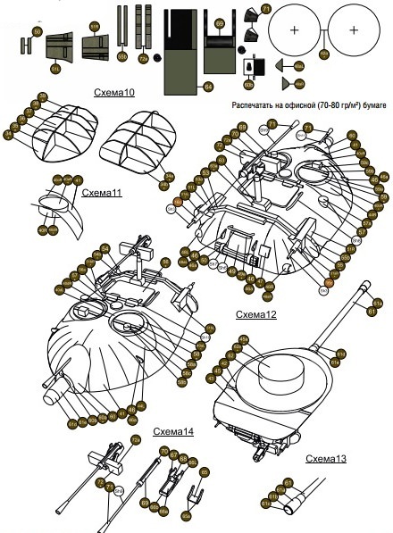
- for printing a model matte photo paper with a density of 170-180 g / m2; for small parts - 70-80 g / m2.
- before assembling the part, read the drawings and instructions. Determine the location of each part and imagine its assembly;
- make holes in the parts before cutting the part itself;
- cut only the part (s) that you need right now. Unfixed parts are put in a box, and unused sheets in a closed folder (as an option). Throwing out garbage after work, carefully inspect paper scraps;
- for better bending of the part, it is necessary to draw a ruler along the bend line, gently pressing with the blunt side of the knife or a toothpick so as not to damage the surface of the paper. It is better to do this from the wrong side of the part;
- keep your fingers clean and be sure to use wipes to wipe your hands, because during the work your hands may get dirty;
- wrap cylindrical parts onto a round object of suitable diameter before gluing, this will give them a shape;
- before gluing, it is necessary to paint over the ends of the part. White trim lines spoil the overall look of the model. To paint the ends, use watercolor or gouache paints. After choosing the right color, apply them in a thin layer, then give the paint time to dry. It is better to forget about felt-tip pens;
- take your time with gluing. First, cut the part, paint it from the end, wait for the paint to dry, assemble the part. Attach it to the place where it should be, to make sure that everything is done correctly. And only then stick. Remember to let the glue dry.
A bit of history
Soviet medium tank T-34 arr. 1940 and 1942


Tank T-34 (photo) Tank T-34 (photo) Tank T-34 (photo) _1 Tank T-34 (photo) _1
On October 13, 1937, ABTU issued the plant technical requirements for the design of a new combat vehicle - the BT-20 wheeled-tracked tank. Two weeks later, the director of plant No. 183, Yu.E. Maksarev, received an order from Glavka that said: “By a decision of the Government No. 94ss of August 15, 1937, the Main Directorate was asked to design and manufacture prototypes and prepare production for serial production by 1939 high-speed wheeled-tracked tanks with synchronized progress. "
To develop a new tank, ABTU sent captain E.A. Kulchitsky, a 3rd-level military engineer A.Ya. Dik, engineers P.P. Vasilyev, V.G. Matyukhin, Vodopyanov, as well as 41 VAMM students to Kharkov. In turn, the plant identified several of its designers, including A.A. Morozov. A.Ya. Dick, assistant to the chief engineer P.N. Information about the activities of this team, which have so far been discovered, breaks off in early November 1937. However, it is reliably known that the TTT for the BT-20 tank (factory index - A-20) was largely based on the development of A.Ya. Dick made in the summer of 1937.
The technical design of the tracked tank, which received the designation A-32, was completed quickly, because outwardly it was no different from the A-20, except for the chassis, which had 5 (and not 4, like the A-20) track rollers on the side. In August 1938, both projects were presented at a meeting of the Main Military Council of the Red Army at the People's Commissariat of Defense. The general opinion of the participants again leaned in favor of a wheeled-tracked tank. And again the decisive role was played by the position of Stalin: he proposed to build and test both tanks and only after that make a final decision.
On September 23, 1939, tank equipment was shown to the leadership of the Red Army, which was attended by K.E. Voroshilov, A.A. Zhdanov, A.I. Mikoyan, N.A. Voznesensky, D.G. Pavlov and others, as well as the main designers of the tanks presented. In addition to the A-20 and A-32, heavy tanks KB, CM K and T-100, as well as light BT-7Ms and T-26s, were delivered to the Moscow training ground.
A-32 "made" very spectacularly. Easily, even elegantly and at a good pace, the tank overcame a moat, an escarp, a counter-escarp, a lance bridge, ford the river, climbed a slope with a rise of more than 30 ° and finally knocked down a large pine with the bow of the armored hull, inspiring the audience.
According to the results of the tests and the show, it was suggested that the A-32 tank, which had a reserve for increasing mass, it was advisable to protect more powerful 45-mm armor, respectively increasing the strength of individual parts.
In an extremely short time, the design bureau finalized the T-32 tank by further enhancing armor protection, armament and implementing a number of other design changes. As a result of this work, a model of the tank was created, which received the name T-34 and later became the main tank of the Soviet Army during the Great Patriotic War. The chief designer of the integrated design bureau developing the T-34 was M.I. Koshkin, head of design bureau and deputy chief designer - A.A. Morozov, Deputy Head of the Design Bureau - N.A. Kucherenko.
The T-34 tank was adopted by the Government Decree on December 19, 1939 before the production of prototypes. The first experimental tanks were made in January 1940 and during testing fully confirmed the high technical and combat qualities. In March 1940, two T-34 tanks made a run to Moscow and vice versa, while showing high reliability of all nodes. In this run was directly involved M.I. Koshkin. In June 1940, the government decided to expand the production of T-34 tanks at other large enterprises in the country. In this regard, the design bureau of the plant No. 183 urgently produced complete sets of drawing and technical documentation for the T-34 tank and sent it in the necessary quantities to the Stalingrad Tractor and Sormovsky Shipbuilding Yards.