Zener diode: in detail in simple language. Correct connection of LEDs
A zener diode is a semiconductor diode with unique properties. If an ordinary semiconductor, when turned back on, is an insulator, then it performs this function until a certain increase in the applied voltage, after which an avalanche-like reversible breakdown occurs. With a further increase in the reverse current flowing through the zener diode, the voltage continues to remain constant due to a proportional decrease in resistance. In this way it is possible to achieve a stabilization regime.
In the closed state, a small leakage current initially passes through the zener diode. The element behaves like a resistor, the value of which is high. During breakdown, the resistance of the zener diode becomes insignificant. If you continue to increase the voltage at the input, the element begins to heat up and when the current exceeds the permissible value, an irreversible thermal breakdown occurs. If the matter is not brought to this point, when the voltage changes from zero to the upper limit of the working area, the properties of the zener diode are preserved.
When a zener diode is directly switched on, the characteristics are no different from a diode. When the plus is connected to the p-region and the minus to the n-region, the junction resistance is low and current flows freely through it. It increases with increasing input voltage.

A zener diode is a special diode, mostly connected in the opposite direction. The element is initially in the closed state. When an electrical breakdown occurs, the voltage zener diode maintains it constant over a wide current range.

Minus is applied to the anode, and plus is applied to the cathode. Beyond stabilization (below point 2), overheating occurs and the likelihood of element failure increases.
Characteristics
The parameters of the zener diodes are as follows:
- U st - stabilization voltage at rated current I st;
- Ist min - minimum current of the beginning of electrical breakdown;
- Ist max - maximum permissible current;
- TKN - temperature coefficient.
Unlike a conventional diode, a zener diode is a semiconductor device in which the areas of electrical and thermal breakdown are located quite far from each other on the current-voltage characteristic.
Associated with the maximum permissible current is a parameter often indicated in tables - power dissipation:
P max = I st max ∙ U st.
The dependence of the zener diode operation on temperature can be either positive or negative. By connecting elements in series with coefficients of different signs, precision zener diodes are created that are independent of heating or cooling.

Connection schemes
A typical circuit of a simple stabilizer consists of a ballast resistance R b and a zener diode that shunts the load.
In some cases, stabilization is disrupted.
- Supplying a high voltage to the stabilizer from the power source with a filter capacitor at the output. Current surges during charging can cause failure of the zener diode or destruction of resistor Rb.
- Load shedding. When the maximum voltage is applied to the input, the zener diode current may exceed the permissible value, which will lead to its heating and destruction. Here it is important to comply with the passport safe work area.
- The resistance R b is selected small so that at the minimum possible value of the supply voltage and the maximum permissible current on the load, the zener diode is in the operating control zone.
To protect the stabilizer, thyristor protection circuits or
Resistor R b is calculated by the formula:
R b = (U pit - U nom)(I st + I n).
Zener diode current I st is selected between the permissible maximum and minimum values, depending on the input voltage U supply and load current I n.
Selection of zener diodes
The elements have a large spread in stabilization voltage. To obtain the exact value of U n, zener diodes are selected from the same batch. There are types with a narrower range of parameters. For high power dissipation, the elements are installed on radiators.
To calculate the parameters of a zener diode, initial data is required, for example, the following:
- U supply = 12-15 V - input voltage;
- U st = 9 V - stabilized voltage;
The parameters are typical for devices with low energy consumption.
For a minimum input voltage of 12 V, the load current is selected to the maximum - 100 mA. Using Ohm's law, you can find the total load of the circuit:
R∑ = 12 V / 0.1 A = 120 Ohm.
The voltage drop across the zener diode is 9 V. For a current of 0.1 A, the equivalent load will be:
R eq = 9 V / 0.1 A = 90 Ohm.
Now you can determine the ballast resistance:
R b = 120 Ohm - 90 Ohm = 30 Ohm.
It is selected from the standard series, where the value coincides with the calculated one.
The maximum current through the zener diode is determined taking into account the load disconnection, so that it does not fail if any wire is unsoldered. The voltage drop across the resistor will be:
U R = 15 - 9 = 6 V.
Then the current through the resistor is determined:
I R = 6/30 = 0.2 A.
Since the zener diode is connected in series, I c = I R = 0.2 A.
The dissipation power will be P = 0.2∙9 = 1.8 W.
Based on the obtained parameters, a suitable D815V zener diode is selected.
Symmetrical Zener diode
A symmetrical diode thyristor is a switching device that conducts alternating current. A feature of its operation is the voltage drop to several volts when turned on in the range of 30-50 V. It can be replaced by two back-to-back conventional zener diodes. The devices are used as switching elements.
Zener diode analogue
When it is not possible to select a suitable element, an analogue of a zener diode on transistors is used. Their advantage is the ability to regulate voltage. For this purpose, DC amplifiers with several stages can be used.

A voltage divider with R1 is installed at the input. If the input voltage increases, at the base of transistor VT1 it also increases. At the same time, the current through transistor VT2 increases, which compensates for the increase in voltage, thereby maintaining it stable at the output.
Marking of zener diodes
Glass zener diodes and zener diodes in plastic cases are produced. In the first case, 2 numbers are applied to them, between which the letter V is located. The inscription 9V1 means that U st = 9.1 V.

The inscriptions on the plastic case are deciphered using a datasheet, where you can also find out other parameters.
The dark ring on the body indicates the cathode to which the plus is connected.
Conclusion
A zener diode is a diode with special properties. The advantage of zener diodes is a high level of voltage stabilization over a wide range of operating current changes, as well as simple connection diagrams. To stabilize the low voltage, the devices are turned on in the forward direction, and they begin to work like ordinary diodes.
Stable salary, stable life, stable state. The last one is not about Russia, of course :-). If you look in an explanatory dictionary, you can clearly understand what “stability” is. On the first lines, Yandex immediately gave me the designation of this word: stable - this means constant, stable, not changing.
But most often this term is used in electronics and electrical engineering. In electronics, constant values of a parameter are very important. This can be current, voltage, signal frequency, etc. Deviation of the signal from any given parameter can lead to incorrect operation of the electronic equipment and even to its breakdown. Therefore, in electronics it is very important that everything works stably and does not fail.
In electronics and electrical engineering stabilize the voltage. The operation of electronic equipment depends on the voltage value. If it changes to a lesser extent, or even worse, to an increase, then the equipment in the first case may not work correctly, and in the second case it may even burst into flames.
In order to prevent voltage spikes and drops, various Surge Protectors. As you understand from the phrase, they are used to stabilize“playing” voltage.
Zener diode or Zener diode
The simplest voltage stabilizer in electronics is a radio element zener diode. Sometimes it is also called Zener diode. In the diagrams, zener diodes are designated something like this:
The terminal with a “cap” is called the same as that of a diode - cathode, and the other conclusion is anode.
Zener diodes look the same as diodes. In the photo below, on the left is a popular type of modern zener diode, and on the right is one of the samples from the Soviet Union
.JPG)
If you take a closer look at the Soviet zener diode, you can see this schematic designation on it itself, indicating where its cathode is and where its anode is.

Stabilization voltage
The most important parameter of a zener diode is, of course, stabilization voltage. What is this parameter?
Let's take a glass and fill it with water...

No matter how much water we pour into a glass, its excess will pour out of the glass. I think this is understandable to a preschooler.
Now by analogy with electronics. The glass is a zener diode. The water level in a glass full to the brim is stabilization voltage Zener diode. Imagine a large jug of water next to a glass. We will just fill our glass with water from the jug, but we don’t dare touch the jug. There is only one option - pour water from a jug by punching a hole in the jug itself. If the jug were smaller in height than the glass, then we would not be able to pour water into the glass. To explain it in electronics terms, the jug has a “voltage” greater than the “voltage” of the glass.

So, dear readers, the whole principle of operation of a zener diode is contained in the glass. No matter what stream we pour on it (well, of course, within reason, otherwise the glass will carry away and break), the glass will always be full. But it is necessary to pour from above. This means, The voltage we apply to the zener diode must be higher than the stabilization voltage of the zener diode.
Marking of zener diodes
In order to find out the stabilization voltage of the Soviet zener diode, we need a reference book. For example, in the photo below there is a Soviet zener diode D814V:

We look for parameters for it in online directories on the Internet. As you can see, its stabilization voltage at room temperature is approximately 10 Volts.

Foreign zener diodes are marked more easily. If you look closely, you can see a simple inscription:
.JPG)
5V1 - this means the stabilization voltage of this zener diode is 5.1 Volts. Much easier, right?
The cathode of foreign zener diodes is marked mainly with a black stripe
.JPG)
How to check zener diode
How to check the zener diode? Yes, just like! You can see how to check the diode in this article. Let's check our zener diode. We set it to continuity and attach the red probe to the anode, and the black probe to the cathode. The multimeter should show a forward voltage drop.
.JPG)
We swap the probes and see one. This means that our zener diode is in full combat readiness.
.JPG)
Well, it's time for experiments. In the circuits, a zener diode is connected in series with a resistor:

Where Uin – input voltage, Uout.st. – output stabilized voltage
If we look closely at the diagram, we get nothing more than a voltage divider. Everything here is elementary and simple:
Uin=Uout.stab +Uresistor
Or in words: the input voltage is equal to the sum of the voltages on the zener diode and the resistor.
This scheme is called parametric stabilizer on one zener diode. The calculation of this stabilizer is beyond the scope of this article, but if anyone is interested, google it ;-)
So, let's put together the circuit. We took a resistor with a nominal value of 1.5 Kilohms and a zener diode with a stabilization voltage of 5.1 Volts. On the left we connect the Power Supply, and on the right we measure the resulting voltage with a multimeter:
.JPG)
Now we carefully monitor the readings of the multimeter and power supply:
.JPG)
So, while everything is clear, let’s add more tension... Oops! Our input voltage is 5.5 Volts, and our output voltage is 5.13 Volts! Since the stabilization voltage of the zener diode is 5.1 Volts, as we can see, it stabilizes perfectly.
.JPG)
Let's add some more volts. The input voltage is 9 Volts, and the zener diode is 5.17 Volts! Amazing!
.JPG)
We also add... The input voltage is 20 Volts, and the output, as if nothing had happened, is 5.2 Volts! 0.1 Volt is a very small error, it can even be neglected in some cases.
.JPG)
Volt-ampere characteristic of a zener diode
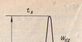
I think it wouldn’t hurt to consider the current-voltage characteristic (VAC) of the zener diode. It looks something like this:

Where
Ipr– forward current, A
Upr– forward voltage, V
These two parameters are not used in the zener diode
Uarr– reverse voltage, V
Ust– rated stabilization voltage, V
Ist– rated stabilization current, A
Nominal means a normal parameter at which long-term operation of the radio element is possible.
Imax– maximum zener diode current, A
Immin– minimum zener diode current, A
Ist, Imax, Imin – This is the current that flows through the zener diode when it operates.
Since the zener diode operates in reverse polarity, unlike a diode (the zener diode is connected with the cathode to the plus, and the diode with the cathode to the minus), then the working area will be exactly the one marked with the red rectangle.

As we see, at some voltage Urev our graph begins to fall down. At this time, such an interesting thing as a breakdown occurs in the zener diode. In short, it can no longer increase the voltage on itself, and at this time the current in the zener diode begins to increase. The most important thing is not to overdo the current, more than Imax, otherwise the zener diode will be damaged. The best operating mode of the zener diode is considered to be the mode in which the current through the zener diode is somewhere in the middle between its maximum and minimum values. This is what will appear on the graph operating point operating mode of the zener diode (marked with a red circle).

Conclusion
Previously, in times of scarce parts and the beginning of the heyday of electronics, a zener diode was often used, oddly enough, to stabilize the output voltage. In old Soviet books on electronics you can see this section of the circuit of various power supplies:

On the left, in the red frame, I marked a section of the power supply circuit that is familiar to you. Here we get DC voltage from AC voltage. On the right, in the green frame, is the stabilization diagram ;-).
Currently, three-terminal (integrated) voltage stabilizers are replacing stabilizers based on zener diodes, since they stabilize the voltage many times better and have good power dissipation.
On Ali you can immediately take a whole set of zener diodes, ranging from 3.3 Volts to 30 Volts. Choose to your taste and color.

19. Serial and parallel connection of power diodes, calculation of equalizing elements.
Currently, power diodes have been created for currents over 1000 A and voltages over 1000 V.
When diodes are connected in series and in parallel, due to the mismatch of their current-voltage characteristics, uneven distributions of voltages or currents arise between individual diodes. In Fig. Figure 1.3 shows the following diagrams: serial (Fig. 1.3, a) and parallel (Fig. 1.3, 6) connections of two diodes. The forward (Fig. 1.3, d) and reverse (Fig. 1.3, c) branches of the current-voltage characteristics of the connected diodes are also presented there. According to the given current-voltage characteristics when diodes are connected in series, the reverse voltage U R applied to them at the same reverse currents I R is distributed unevenly between the diodes: voltage U R 1 is applied to diode VD1, and voltage U R 2 is applied to diode VD 2 (Fig. 1-3, c) . When diodes are connected in parallel, the total current I F flowing through them at equal forward voltage drops U F is also distributed unevenly: current I F 1 flows through diode VD 1, and current I F 2 flows through diode VD2 (Fig. 1.3d). To prevent failure of diodes due to overcurrent or overvoltage, special measures are taken to equalize the specified parameters between individual diodes. When diodes are connected in series, resistors connected in parallel to the diodes are usually used to equalize the voltages, and inductive dividers of various types are used when connected in parallel.


Rice. 1.3. Series and parallel connection of diodes
20. Power zener diodes and voltage limiters, symbol, main parameters and voltage, areas of use.
Zener diode (Zener diode) is a semiconductor diode designed to maintain the voltage of the power source at a given level. Compared to conventional diodes, it has a fairly low regulated breakdown voltage (when turned on in reverse) and can maintain this voltage at a constant level even with a significant change in the reverse current strength. The materials used to create the p-n junction of zener diodes have a high concentration of alloying elements (impurities). Therefore, at relatively small reverse voltages, a strong electric field arises in the junction, causing its electrical breakdown, which in this case is reversible (if thermal breakdown does not occur due to too much current). The operation of the zener diode is based on two mechanisms: Avalanche breakdown of the p-n junction
Tunnel breakdown of a p-n junction (Zener effect in English literature). Despite the similar results of action, these mechanisms are different, although they are present together in any zener diode, but only one of them predominates. For zener diodes up to a voltage of 5.6 volts, tunnel breakdown with a negative temperature coefficient predominates [source not specified 304 days], above 5.6 volts avalanche breakdown with a positive temperature coefficient becomes dominant [source not specified 304 days]. At a voltage of 5.6 volts, both effects are balanced, so choosing this voltage is the optimal solution for devices with a wide temperature range of use [source not specified 321 days]. The breakdown mode is not associated with the injection of minority charge carriers. Therefore, in a zener diode, injection phenomena associated with the accumulation and resorption of charge carriers during the transition from the breakdown region to the blocking region and back are practically absent. This allows them to be used in pulse circuits as level clamps and limiters.
Types of zener diodes: precision- have increased stability of stabilization voltage, for which additional standards are introduced for temporary voltage instability and temperature coefficient of voltage (for example: 2S191, KS211, KS520); bilateral- provide stabilization and limitation of bipolar voltages, for which the absolute value of the stabilization voltage asymmetry is additionally normalized (for example: 2S170A, 2S182A); fast-acting- have a reduced barrier capacitance value (tens of pF) and a short duration of the transient process (units ns), which makes it possible to stabilize and limit short-term voltage pulses (for example: 2S175E, KS182E, 2S211E).
There are microcircuits of linear voltage regulators with two terminals, which have the same connection circuit as the zener diode, and often the same designation on electrical circuit diagrams.
Typical circuit for switching on a zener diode 
Designation of a zener diode on circuit diagrams 
Designation of a two-anode zener diode on circuit diagrams 
Options. Stabilization voltage- the voltage value on the zener diode during the passage of a given stabilization current. The breakdown voltage of the diode, and therefore the stabilization voltage of the zener diode, depends on the thickness of the p-n junction or on the resistivity of the diode base. Therefore, different zener diodes have different stabilization voltages (from 3 to 400 V). Temperature coefficient of voltage stabilization- a value determined by the ratio of the relative change in ambient temperature at a constant stabilization current. The values of this parameter are different for different zener diodes. The coefficient can have both positive and negative values for high-voltage and low-voltage zener diodes, respectively. The change in sign corresponds to a stabilization voltage of about 6V. Differential resistance- a value determined by the ratio of the stabilization voltage increment to the small current increment that caused it in a given frequency range. Maximum permissible power dissipation- maximum constant or average power dissipated on the zener diode, at which the specified reliability is ensured.
Correct connection of LEDs. How to connect a zener diode to a circuit
How to properly connect an LED
An LED is an ordinary diode in which substances have been added to the crystal that emit light when an electric current passes through them. When a positive voltage is applied to the anode and a negative voltage to the cathode, a glow occurs. The most common cause of failure is exceeding the nominal supply voltage.
 On the circuit diagrams the pinout is clear. We always apply “minus” to the cathode, which is why it is designated by a straight line at the vertex of the triangle. Typically, the cathode is the contact on which the light-emitting crystal is located. It is wider than the anode.
In super-bright LEDs, polarity is usually marked on the contacts or housing. If there are no markings on the contact legs, the leg with a wider base is the cathode.
LED connection diagram

In the classical circuit, it is recommended to connect through a current-limiting resistor. Indeed, by choosing the right resistor or inductive reactance, you can connect a diode designed for a 3V supply voltage, even to an alternating current network.
The main requirement for power parameters is limiting the circuit current.
Since current strength is a parameter that reflects the density of electron flow through a conductor, if this parameter is exceeded, the diode will simply explode due to the instantaneous and significant release of heat on the semiconductor crystal.
How to calculate a limiting resistor
- R is the resistance of the limiting resistor in ohms;
- Upit - power source voltage in volts;
- Upad - LED supply voltage;
- I is the rated current of the LED in amperes.
If the resistor power is significantly less than required, it will simply burn out due to overheating.
Turning on an LED via a power supply without a resistor
I have had a table lamp upgraded to LED for several years now. Six bright LEDs are used as a light source, and an old Nokia mobile phone charger is used as a power source. Here is my LED switching diagram:

The rated voltage of the diodes is 3.5V, current is 140mA, power is 1W.
When selecting an external power source, current limitation is required. Connecting these LEDs to modern chargers with a supply voltage of 5V 1-2A will require a limiting resistor.
To adapt this circuit to a 5V charger, use a 10-20 Ohm resistor with a power of 0.3A.

If you have a different power source, make sure it has a current regulation circuit.
How to properly connect LEDs
Parallel connection
The easiest way to determine diode compatibility is to use a low-voltage or regulated power supply. You can navigate by the “ignition voltage,” when the crystal begins to glow just a little. When the “starting” voltage varies by 0.3-0.5 V, a parallel connection without a current-limiting resistor is unacceptable.
Serial connection
Calculation of resistance for a circuit of several diodes: R = (Upit - N * Usd) / I * 0.75
Maximum number of series diodes: N = (Upit * 0.75) / Usd
When connecting several successive LED chains, it is advisable to calculate its own resistor for each chain.

How to turn on an LED in AC power
If, when connecting an LED to a direct current source, electrons move only in one direction and it is enough to limit the current using a resistor, in an alternating voltage network the direction of electron movement is constantly changing.

When a positive half-wave passes, the current, passing through a resistor that absorbs excess power, ignites the light source. The negative half-wave will go through a closed diode. For LEDs, the reverse voltage is small, about 20V, and the amplitude voltage of the network is about 320V.
 The semiconductor will operate in this mode for some time, but a reverse breakdown of the crystal is possible at any moment. To avoid this, an ordinary rectifier diode is installed in front of the light source, which can withstand reverse current up to 1000 V. It will not pass the reverse half-wave into the electrical circuit.
The connection diagram for the AC network is in the figure on the right.
Other types of LED
Flashing
 A design feature of a flashing LED is that each contact is both a cathode and an anode. Inside it are two light-emitting crystals with different polarities. If such a light source is connected through a step-down transformer to an alternating current network, it will blink at a frequency of 25 times per second.
For other blinking frequencies, special drivers are used. Now such diodes are no longer used.
Multicolored
Multi-colored LED - two or more diodes combined into one housing. Such models have one common anode and several cathodes.

By changing the brightness of each matrix through a special power driver, you can achieve any luminous light.
When using such elements in homemade circuits, do not forget that different-colored crystals have different supply voltages. This point must be taken into account when connecting a large number of multi-colored LED sources.

Another option is a diode with a built-in driver. Such models can be two-color with alternate inclusion of each color. The blinking frequency is set by the built-in driver.
A more advanced option is an RGB diode that changes color according to a program pre-installed in the chip. Here, the lighting options are limited only by the manufacturer’s imagination.
svetodiodinfo.ru
Parallel connection - zener diode - Big Encyclopedia of Oil and Gas, article, page 1
Parallel connection - zener diode
Page 1
Parallel connection of zener diodes to increase power is not allowed, since due to the insufficient identity of the current-voltage characteristics of the diodes connected in parallel, it is impossible to distribute the currents evenly between them. The stabilization current passing through one diode can vary from 1 to 30 mA and, therefore, can compensate for a change in load current only by this amount. Thus, the control limits for load currents of hundreds of milliamps are insufficient. To expand the limits of permissible fluctuations in input voltage and load current, a transistor is included in the stabilization circuit as an emitter follower.
Parallel connection of zener diodes is not allowed.
Parallel connection of zener diodes is not used, since different zener diodes have different ignition voltages and stabilization voltages. As a result, when voltage is applied, only one zener diode, which has the lowest voltage, lights up.
Parallel connection of zener diodes is allowed provided that the stabilization current passing through each zener diode must be within acceptable limits. Any number of zener diodes can be connected in series.
Parallel connection of zener diodes is not used, since different instances of zener diodes of this type do not have the same ignition voltages. Therefore, in a parallel connection, as a rule, only the zener diode with the lowest ignition voltage is ignited.
Parallel connection of zener diodes is unacceptable, since due to the inevitable scatter of parameters, the current of the zener diode with the lowest breakdown voltage will be many times greater than the currents through the remaining diodes.
Parallel connection of zener diodes and stabilizers is not used, since due to the difference in their resistances, the current will be distributed unevenly between them. As a result, the zener diode with less resistance will be overloaded and the stabilizer will be unreliable in operation.
Parallel connection of zener diodes is allowed, provided that the stabilization current passing through each zener diode must be within acceptable limits. Any number of zener diodes can be connected in series.
To increase the stabilized voltage, a series connection of zener diodes is used; Parallel connection of zener diodes is not used, since it is impossible to select zener diodes with absolutely identical parameters.
During operation, the zener diode must be switched on with the polarity reverse to that indicated on the zener diode body. Parallel connection of zener diodes is allowed only under the condition that the stabilization current passing through each zener diode must be within acceptable limits.
Any number of zener diodes can be connected in series. Parallel connection of zener diodes is allowed provided that the total power dissipated by all parallel-connected zener diodes does not exceed the maximum power for one zener diode, and the current flowing through each zener diode does not exceed the maximum and minimum values.
Any number of zener diodes can be connected in series. Parallel connection of zener diodes is allowed provided that the total power dissipation on all parallel-connected zener diodes does not exceed the maximum permissible power dissipation for one zener diode.
Pages: 1 2
www.ngpedia.ru
How to connect an LED in parallel, in series: diagrams, descriptions, nuances
Light-emitting diodes (also known as led) have been actively used for many years both in the production of televisions and as the main lighting of a house or apartment, but the question of how to properly connect LEDs is still relevant today.
Today there are a huge number of them, of varying power (super-bright Piranha), operating on constant voltage, which can be connected in three ways:
- Parallel.
- Consistently.
- Combined.
There are also specially designed circuits that allow you to connect the LED to a stationary 220V household network. Let's take a closer look at all the LED connection options, their advantages and disadvantages, as well as how to do it yourself.
Basic principles of connection
As mentioned earlier, the design of a light-emitting diode involves connecting them exclusively to a direct current source. However, since the working part of the LED is a semiconductor silicon crystal, it is very important to maintain polarity, otherwise the LED will not emit a luminous flux.
Each LED has technical documentation, which contains instructions and directions for correct connection. If there is no documentation, you can look at the LED markings. The marking will help you identify the manufacturer, and knowing the manufacturer, you can find the required datasheet, which contains information on the connection. Here, this is not a tricky piece of advice.
How to determine polarity?
There are only 3 ways to resolve the issue:

We've sorted out the polarity, now we need to decide how to connect the LED to the network. For those who do not understand, read a detailed and interesting article on determining the polarity of an LED. In it we have collected all possible methods of checking, and even using a battery.
Connection methods
Conventionally, connection occurs in 2 ways:
- To a stationary network of industrial frequency (50Hz) with a voltage of 220V;
- To a network with a safe voltage of 12V.
If you need to connect several LEDs to one power source, then you need to choose a serial or parallel connection.
Let's look at each of the above examples separately.
Connecting LEDs to 220V voltage
The first thing you need to know when connecting to a 220V network is that for a nominal glow, a current of 20 mA must pass through the LED, and the voltage drop across it should not exceed 2.2-3V. Based on this, it is necessary to calculate the value of the current-limiting resistor using the following formula:

in which 0.75 is the reliability coefficient of the led, U pit is the voltage of the power source, U pad is the voltage that drops across the light-emitting diode and creates the luminous flux, I is the rated current passing through it, and R is the nominal resistance for regulating the passing current After appropriate calculations, the resistance value should correspond to 30 kOhm.
However, do not forget that a large amount of heat will be generated at the resistance due to the voltage drop. For this reason, it is additionally necessary to calculate the power of this resistor using the formula:

For our case, U will be the difference between the supply voltage and the drop voltage across the LED. After appropriate calculations, to connect one LED, the resistance power should be 2W.
After determining the rating and power of the resistance, you can assemble a circuit to connect one LED to 220V. For its reliable operation, it is necessary to install an additional diode that will protect the light-emitting diode from breakdown when an amplitude voltage of 315V (220*√2) occurs at the LED terminals.

The circuit is practically not used, since it causes very large losses due to heat generation in the resistance. Let's consider a more efficient connection diagram to 220 V:

In the diagram, as we can see, a reverse diode VD1 is installed, which passes both half-waves to the capacitor C1 with a capacity of 220 nF, on which the voltage drops to the required nominal value.
Resistance R1 with a nominal value of 240 kOhm discharges the capacitor when the network is turned off, and does not play any role during operation of the circuit.
But this is a simplified model for connecting LEDs; most LED lamps already have a built-in driver (circuit) that converts 220V AC voltage into 5-24V DC voltage for their reliable operation. You can see the driver circuit in the following photo:

Connecting LEDs to a 12V network
12 volts is a safe voltage that is used in particularly hazardous areas. These include bathrooms, baths, inspection pits, underground structures and other premises.
To connect to a DC voltage source rated 12V, similarly, to connect to 220V networks, a damping resistance is required. Otherwise, if you connect it directly to the source, the LED will instantly burn out due to the larger current flowing through.
The nominal value of this resistance and its power are calculated using the same formulas:
Unlike 220V circuits, to connect one LED to a 12V network we need a resistance with the following characteristics:
- R = 1.3 kOhm;
- P = 0.125W.
Another advantage of the 12V voltage is that in most cases it is already rectified (constant), which greatly simplifies the connection diagram. It is recommended to additionally install a voltage stabilizer such as KREN or an equivalent.

As we already know, a light-emitting diode can be connected to both 12V and 220V circuits, however, there are several variations of their connection to each other:
- Consistent.
- Parallel.
Serial connection
When connected in series through a current-limiting resistor, several LEDs are assembled into one chain, and the cathode of the previous one is soldered to the anode of the next one:

In the circuit, one current (20mA) will flow through all LEDs, and the voltage level will consist of the sum of the voltage drop across each. This means that using this connection diagram, you cannot include any number of LEDs in the circuit, because it is limited by voltage drop.
Voltage drop is the level of voltage that a light-emitting diode converts into light energy (glow).
For example, in the circuit the voltage drop across one LED will be 3 Volts. There are a total of 3 LEDs in the circuit. Power supply 12V. We consider 3 Volts * 3 led = 9 V - voltage drop.
After simple calculations, we see that we cannot include more than 4 LEDs (3 * 4 = 12V) in a parallel connection circuit, powering them from a regular car battery (or other source with a voltage of 12V).
If we want to connect more LEd in series, we will need a power supply with a higher rating.
This scheme was quite often found in Christmas tree garlands, however, due to one significant drawback, modern LED garlands use a mixed connection. We'll look at what the drawback is below.
Disadvantages of daisy chaining
- If at least one element fails, the entire circuit becomes inoperative;
- To power a large number of LEDs you need a high voltage source.
Parallel connection
In this situation, everything happens the other way around. Each LED has the same voltage level, and the current is the sum of the currents passing through them.

Following from the above, we conclude that if we have a 12V source and 10 LEDs, the power supply must withstand a load of 0.2A (10 * 0.002).
Based on the above calculations, for a parallel connection you will need a current-limiting resistor with a nominal value of 2.4 Ohms (12 * 0.2).
This is a deep misconception!!! Why? You will find the answer below
The characteristics of each LED, even of the same series and batch, are always different. In other words: in order for one to light up, it is necessary to pass through it a current with a nominal value of 20 mA, and for the other this nominal value may already be 25 mA.
Thus, if only one resistance is installed in the circuit, the nominal value of which was calculated earlier, different currents will flow through the LEDs, which will cause overheating and failure of LEDs designed for a nominal value of 18 mA, and more powerful ones will shine at only 70% of the nominal value .
Based on the above, it is worth understanding that when connecting in parallel, it is necessary to install a separate resistance for each.

Disadvantages of parallel connection:
- A large number of elements;
- When one diode fails, the load on the others increases.
Mixed connection
This connection method is the most optimal. All LED strips are assembled using this principle. It involves a combination of parallel and serial connections. You can see how it is done in the photo:

The circuit involves connecting in parallel not individual LEDs, but serial chains of them. As a result of this, even if one or more chains fail, the LED garland or strip will still shine equally.
We looked at the main ways to connect simple LEDs. Now let's look at the methods for connecting high-power LEDs, and what problems you may encounter if connected incorrectly.
How to connect a powerful LED?
For powerful light-emitting diodes to work, just like simple ones, we need a power source. However, unlike the previous version, it should be an order of magnitude more powerful.
To illuminate a powerful 1W LED, the power source must withstand at least 350 mA of load. If the rating is 5W, then the DC power source must withstand a current load of at least 1.4A.
For the correct operation of a high-power LED, it is necessary to use an integrated voltage stabilizer of the LM type, which protects it from voltage surges.

If you need to connect not one, but several powerful LEDs, we recommend that you familiarize yourself with the rules for serial and parallel connection, which were described above.
Connection errors

Video
Connection errors can lead to unpleasant consequences, from simple breakdown of LEDs to self-harm. Therefore, we strongly recommend watching a video where common errors are discussed.
Conclusion
After reading the article, we can conclude that all LEDs, regardless of the operating voltage, are always connected in parallel or in series - a school physics course. It is also worth remembering that no LED is connected directly to a 220V network; you should always use protective elements in the connection diagram. The type of protective elements used depends on the type of light-emitting diode being connected.
ledno.ru
TL 431 zener diode, switching circuits, regulator characteristics
 TL 431 is a programmable shunt voltage regulator. Although this integrated circuit began to be produced in the late 70s, it still does not lose its position in the market and is popular among radio amateurs and large manufacturers of electrical equipment. The board of this programmable stabilizer contains a photoresistor, a resistance measurement sensor and a thermistor. TL 431 are widely used in a wide variety of electrical appliances, household and industrial equipment. Most often, this integrated zener diode can be found in power supplies for computers, televisions, printers and chargers for lithium-ion phone batteries.
TL 431 integrated zener diode
Key Features of the TL 431 Programmable Voltage Reference
- Rated operating voltage at the output is from 2.5 to 36 V;
- Output current up to 100 mA;
- Power 0.2 Watt;
- Operating temperature range for TL 431C from 0° to 70°;
- The operating temperature range for TL 431A is from -40° to +85°.
The accuracy of the TL 431 integrated circuit is indicated by the sixth letter in the designation:
- Accuracy without a letter – 2%;
- Letter A – 1%;
- Letter B – 0.5%.
Its widespread use is due to its low price, universal form factor, reliability, and good resistance to aggressive environmental factors. But it should also be noted the accuracy of this voltage regulator. This allowed him to occupy a niche in microelectronics devices.
 The main purpose of the TL 431 is to stabilize the reference voltage in the circuit. Provided that the voltage at the source input is below the rated reference voltage, the transistor in the programmable module will be closed and the current passing between the cathode and anode will not exceed 1 mA. If the output voltage exceeds the programmed level, the transistor will be open and electric current will be able to freely pass from the cathode to the anode.
Wiring diagram TL 431
 Depending on the operating voltage of the device, the connection circuit will consist of a single-stage converter and expander (for 2.48 V devices) or a small capacity modulator (for 3.3 V devices). And also to reduce the risk of a short circuit, a fuse is installed in the circuit, usually behind the zener diode. The physical connection is influenced by the form factor of the device in which the TL 431 circuit will be located, and environmental conditions (mainly temperature).
Stabilizer based on TL 431
The simplest stabilizer based on the TL 431 is a parametric stabilizer. To do this, you need to include two resistors R 1, R 2 in the circuit through which you can set the output voltage for TL 431 using the formula: U out = Vref (1 + R 1/ R 2). As can be seen from the formula here, the output voltage will be directly proportional to the ratio of R 1 to R 2. The integrated circuit will keep the voltage at 2.5 V. For resistor R 1, the output value is calculated as follows: R 1 = R 2 (U out / Vref - 1).
This regulator circuit is typically used in fixed or variable voltage power supplies. Such voltage stabilizers on the TL 431 can be found in printers, plotters, and industrial power supplies. If it is necessary to calculate the voltage for fixed power supplies, then we use the formula Vo = (1 + R 1/ R 2) Vref.
Timing relay
The precision characteristics of the TL 431 allow it to be used for other than its intended purpose. Due to the fact that the input current of this adjustable stabilizer is from 2 to 4 μA, a temporary relay can be assembled using this chip. The role of a timer in it will be played by R1, which will begin to gradually charge after opening the contacts S 1 C 1. When the voltage at the output of the stabilizer reaches 2.5 V, transistor DA1 will be open, current will begin to flow through the LEDs of the PC 817 optocoupler, and the open photoresistor will close the circuit.
Thermal stabilizer based on TL 431
The technical characteristics of TL 431 make it possible to create thermally stable current stabilizers based on it. In which resistor R2 acts as a feedback shunt, a value of 2.5 V is constantly maintained on it. As a result, the value of the load current will be calculated using the formula In = 2.5/R2.
Pinout and serviceability check of TL 431
The TL 431 form factor and its pinout will depend on the manufacturer. There are options in old TO-92 and new SOT-23 packages. Don’t forget about the domestic analogue: KR142EN19A is also widespread on the market. In most cases, the pinout is applied directly to the board. However, not all manufacturers do this, and in some cases you will have to look for information on pins in the data sheet of a particular device.
TL 431 is an integrated circuit and consists of 10 transistors. Because of this, it is impossible to check it with a multimeter. To check the serviceability of the TL 431 chip, you need to use a test circuit. Of course, there is often no point in looking for a burnt-out element and it is easier to replace the entire circuit.
Calculation programs for TL 431
There are many sites on the Internet where you can download calculator programs to calculate voltage and current parameters. They can indicate the types of resistors, capacitors, microcircuits and other components of the circuit. TL 431 calculators are also available online; they are not as functional as installed programs, but if you only need the input/output and maximum values of the circuit, then they will cope with this task.
instrument.guru
How to connect an LED to 220V: diagrams, errors, nuances, video
Typically, LEDs are connected to 220V using a driver designed for their characteristics. But if you need to connect only one low-power LED, for example, as an indicator, then using a driver becomes impractical. In such cases, the question arises - how to connect the LED to 220 V without an additional power supply.
Basics of connecting to 220 V
Unlike the driver, which supplies the LED with direct current and a relatively low voltage (a few to tens of volts), the network produces an alternating sine-like voltage with a frequency of 50 Hz and an average value of 220 V. Since the LED passes current only in one direction, it will only glow on certain half-waves:

That is, the LED does not glow constantly with this power supply, but blinks at a frequency of 50 Hz. But due to the inertia of human vision, this is not so noticeable.
At the same time, a voltage of reverse polarity, although it does not cause the LED to glow, is still applied to it and can damage it if no protective measures are taken.
Methods for connecting an LED to a 220 V network
The easiest way (read about all possible ways to connect an LED) is to connect using a quenching resistor connected in series with the LED. It should be taken into account that 220 V is the rms value of U in the network. The amplitude value is 310 V, and must be taken into account when calculating the resistance of the resistor.
In addition, it is necessary to protect the light-emitting diode from reverse voltage of the same magnitude. This can be done in several ways.
Series connection of a diode with a high reverse breakdown voltage (400 V or more).
Let's look at the connection diagram in more detail.

The circuit uses a 1N4007 rectifier diode with a reverse voltage of 1000 V. When the polarity is changed, all the voltage will be applied to it, and the led is protected from breakdown.
This connection option is clearly shown in this video:
It also describes how to determine the location of the anode and cathode of a standard low-power LED and calculate the resistance of the quenching resistor.
Bypassing an LED with a conventional diode.
Any low-power diode connected back-to-back with the LED will do here. In this case, the reverse voltage will be applied to the quenching resistor, because the diode turns on in the forward direction.

Back-to-back connection of two LEDs:
The connection diagram looks like this:

The principle is similar to the previous one, only here the light-emitting diodes each burn in their own section of the sinusoid, protecting each other from breakdown.
Please note that connecting an LED to a 220V power supply without protection leads to its rapid failure.
Schemes for connecting to 220V using a quenching resistor have one serious drawback: a large amount of power is released at the resistor.
For example, in the cases considered, a resistor with a resistance of 24 Kom is used, which at a voltage of 220 V provides a current of about 9 mA. Thus, the power dissipated by the resistor is:
9 * 9 * 24 = 1944 mW, approximately 2 W.
That is, for optimal operation you will need a resistor with a power of at least 3 W.
If there are several LEDs, and they consume more current, then the power will increase in proportion to the square of the current, which will make the use of a resistor impractical.
The use of a resistor of insufficient power leads to its rapid overheating and failure, which can cause a short circuit in the network.
In such cases, a capacitor can be used as a current-limiting element. The advantage of this method is that no power is dissipated on the capacitor, since its resistance is reactive.

Shown here is a typical diagram for connecting a light-emitting diode to a 220V network using a capacitor. Since the capacitor, after turning off the power, can retain a residual charge that is dangerous to humans, it must be discharged using resistor R1. R2 protects the entire circuit from current surges through the capacitor when the power is turned on. VD1 protects the LED from reverse polarity voltage.
The capacitor must be non-polar, designed for a voltage of at least 400 V.
The use of polar capacitors (electrolyte, tantalum) in an alternating current network is unacceptable, because current passing through them in the opposite direction destroys their structure.
The capacitor capacity is calculated using the empirical formula:

where U is the amplitude voltage of the network (310 V),
I – current passing through the LED (in milliamps),
Ud – voltage drop across the led in the forward direction.
Let's say you need to connect an LED with a voltage drop of 2 V at a current of 9 mA. Based on this, we calculate the capacitance of the capacitor when connecting one such LED to the network:

This formula is only valid for a network voltage fluctuation frequency of 50 Hz. At other frequencies, a recalculation of the factor 4.45 will be required.
The nuances of connecting to a 220 V network
When connecting an LED to a 220V network, there are some features related to the amount of current passing. For example, in common backlit light switches, the LED is turned on according to the circuit shown below:

As you can see, there are no protective diodes here, and the resistor value is chosen in such a way as to limit the forward current of the LED to about 1 mA. The lamp load also serves as a current limiter. With this connection scheme, the LED will glow dimly, but enough to see the switch in the room at night. In addition, the reverse voltage will be applied mainly to the resistor when the switch is open, and the light-emitting diode will be protected from breakdown.
If you need to connect several LEDs to 220V, you can turn them on in series based on a circuit with a quenching capacitor:

In this case, all LEDs must be designed for the same current for uniform illumination.
You can replace the bypass diode with a back-to-back LED connection:

Parallel (not back-to-back) connection of LEDs to the network is unacceptable, since if one circuit fails, double the current will flow through the other, which will cause the LEDs to burn out and a subsequent short circuit.

Several more options for the unacceptable connection of light-emitting diodes to a 220V network are described in this video:
Here's why you can't:
- turn on the LED directly;
- connect LEDs designed for different currents in series;
- turn on LED without reverse voltage protection.
Connection security
When connecting to 220V, it should be taken into account that the light switch usually opens the phase wire. Zero in this case is carried out common throughout the room. In addition, the electrical network often does not have a protective ground, so even on the neutral wire there is some voltage relative to the ground. You should also keep in mind that in some cases the ground wire is connected to radiators or water pipes. Therefore, when a person comes into simultaneous contact with the phase and the battery, especially during installation work in the bathroom, there is a risk of being exposed to voltage between the phase and the ground.
In this regard, when connecting to the network, it is better to disconnect both the zero and the phase using a batch machine in order to avoid electric shock when touching live wires of the network.
Conclusion
The methods described here for connecting LEDs to a 220V network are advisable to use only when using low-power light-emitting diodes for illumination or indication purposes. Powerful LEDs cannot be connected this way, since instability of the mains voltage leads to their rapid degradation and failure. In such cases, you need to use specialized LED power supplies - drivers.
ledno.ru
| Nikolay Petrushov
TL431 was created in the late 70s and is still widely used in industry and in amateur radio activities. But despite its considerable age, not all radio amateurs are closely familiar with this wonderful case and its capabilities. In this article I will try to familiarize radio amateurs with this microcircuit. First, let's look at what's inside it and turn to the documentation for the microcircuit, the "datasheet" (by the way, analogs of this microcircuit are KA431, and our KR142EN19A, K1156ER5x microcircuits). And inside it has about a dozen transistors and only three outputs, so What is it?
It turns out everything is very simple. Inside there is a conventional op-amp operational amplifier (triangle in the block diagram) with an output transistor and a reference voltage source. Only here this circuit plays a slightly different role, namely the role of a zener diode. It is also called “Controlled Zener Diode”. How does it work? Look at the TL431 block diagram in Figure 2. From the diagram you can see that the op-amp has a (very stable) built-in reference voltage source of 2.5 volts (small square) connected to the inverse input, one forward input (R), a transistor at the output of the op-amp, a collector (K) and an emitter (A), which are combined with the power supply terminals of the amplifier and a protective diode against polarity reversal. The maximum load current of this transistor is up to 100 mA, the maximum voltage is up to 36 volts.
Now, using the example of a simple circuit shown in Figure 4, let’s look at how it all works. We already know that inside the microcircuit there is a built-in reference voltage source - 2.5 volts. In the first releases of microcircuits, which were called TL430, the voltage of the built-in source was 3 volts, in later releases it reaches 1.5 volts. This means that in order for the output transistor to open, it is necessary to apply a little voltage to the input (R) of the operational amplifier exceeding the reference 2.5 volts (the prefix “slightly” can be omitted, since the difference is several millivolts and in the future we will assume that a voltage equal to the reference must be applied to the input), then a voltage will appear at the output of the operational amplifier and the output transistor will open. If To put it simply, TL431 is something like a field-effect transistor (or just a transistor), which opens when a voltage of 2.5 volts (or more) is applied to its input. The opening-closing threshold of the output transistor is very stable here due to the presence of a built-in stable reference voltage source.
From the diagram (Fig. 4) it is clear that a voltage divider made of resistors R2 and R3 is connected to the R input of the TL431 microcircuit, resistor R1 limits the LED current. Since the divider resistors are the same (the power supply voltage is divided in half), the output transistor of the amplifier (TL) -ki) will open when the power source voltage is 5 volts or more (5/2=2.5). In this case, 2.5 volts will be supplied to the input R from the divider R2-R3. That is, our LED will light up (the output transistor will open) when the power source voltage is 5 volts or more. It will go out accordingly when the source voltage is less than 5 volts. If you increase the resistance of resistor R3 in the divider arm, then it will be necessary to increase the voltage of the power source to more than 5 volts, so that the voltage at the R input of the microcircuit supplied from the divider R2-R3 again reached 2.5 volts and the TL-ki output transistor opened. It turns out that if this voltage divider (R2-R3) is connected to the output of the power supply, and the cathode of the TL-ki to the base or gate of the control transistor of the power supply, then by changing the arms of the divider, for example by changing the value of R3, it will be possible to change the output voltage of this power supply, because at the same time, the TL stabilization voltage (opening voltage of the output transistor) will also change - that is, we will get a controlled zener diode. Or if you select a divider without changing it in the future, you can make the output voltage of the power supply strictly fixed at a certain value. Conclusion; - if the microcircuit is used as a zener diode (its main purpose), then by selecting the resistances of the divider R2-R3 we can make a zener diode with any stabilization voltage in the range of 2.5 - 36 volts (maximum limitation according to the “datasheet”). Stabilization voltage is 2 .5 volts - it turns out without a divider, if the input of the TL is connected to its cathode, that is, pins 1 and 3 are short-circuited. Then more questions arise. Is it possible, for example, to replace the TL431 with a regular op-amp? - It is possible only if you want to design it, but you will need to assemble your own 2.5-volt reference voltage source and supply power to the op-amp separately from the output transistor, since its current consumption can open the actuator. In this case, you can make the reference voltage whatever you want (not necessarily 2.5 volts), then you will have to recalculate the resistance of the divider used in conjunction with the TL431, so that at a given output voltage of the power supply, the voltage supplied to the input of the microcircuit is equal to the reference. One more question - is it possible to use the TL431 as a regular comparator and build on it, say, a thermostat, or something similar? It is possible, but since it differs from a conventional comparator in the presence of a built-in reference voltage source, the circuit will be much simpler. For example this;
Here the thermistor (thermistor) is a temperature sensor, and it decreases its resistance as the temperature increases, i.e. has a negative TCR (Temperature Coefficient of Resistance). Thermistors with positive TCS, i.e. whose resistance increases with increasing temperature are called posistors. In this thermostat, when the temperature exceeds a set level (regulated by a variable resistor), a relay or some actuator will operate and switch off the load (heating elements) with its contacts, or, for example, turn on the fans depending on the task .This circuit has a small hysteresis, and to increase it, it is necessary to introduce an OOS between pins 1-3, for example, a trimming resistor of 1.0 - 0.5 mOhm and its value is selected experimentally depending on the required hysteresis. If it is necessary that the actuator triggered when the temperature drops, then the sensor and regulators need to be swapped, that is, the thermistor should be included in the upper arm, and the variable resistance with resistor - in the lower arm. And in conclusion, you can easily figure out how the TL431 microcircuit works in the circuit of a powerful power supply for transceiver, which is shown in Figure 6, and what role resistors R8 and R9 play here, and how they are selected.  List of elements of the circuit diagram
 |
 Rice. 1 TL431.
 Rice. 2 Device TL431.
 Rice. 3 Pinout TL431.
 Rice. 4 Scheme on TL431.
 Rice. 5 Thermostat on TL431.
The simplest parallel stabilizer consists of a ballast resistor connected in series between the power source and the load, and a zener diode that shunts the load to a common wire (“to ground”). It can be thought of as a voltage divider that uses a zener diode as the low side. The difference between the supply voltage and the breakdown voltage of the zener diode drops across the ballast resistor, and the supply current flowing through it branches into the load current and the zener diode current. Stabilizers of this kind are called parametric: they stabilize the voltage due to the nonlinearity of the current-voltage characteristic of the zener diode, and do not use feedback circuits.
The calculation of a parametric stabilizer on semiconductor zener diodes is similar to the calculation of a stabilizer on gas-filled devices, with one significant difference: gas-filled zener diodes are characterized by threshold voltage hysteresis. When there is a capacitive load, the gas-filled zener diode is self-excited, so the designs of such stabilizers usually do not contain capacitive filters, and the designer does not need to take into account transient processes in these filters. In stabilizers based on semiconductor zener diodes, there is no hysteresis; filter capacitors are connected directly to the terminals of the zener diode and the load - as a result, the designer must take into account the surge current of the charge (discharge) of these capacitors when turning the power on (off). The worst cases in which the stabilizer elements are likely to fail or stabilization to fail are:
- Supplying the maximum possible supply voltage to the stabilizer input in the event of a short circuit of the stabilizer output to the common wire - for example, while charging a discharged capacitor connected directly to the stabilizer output, or in the event of a catastrophic failure of the zener diode. The permissible power dissipation of the ballast resistor must be sufficient to withstand such a short circuit. Otherwise, the ballast resistor is likely to be destroyed.
- Supplying the maximum possible supply voltage to the stabilizer input when the load is disconnected from the stabilizer output. The permissible current of the zener diode must exceed the calculated current through the ballast resistor, determined by Ohm's law. Otherwise, when the zener diode crystal is heated above +175 °C, the zener diode is destroyed. Compliance with the safety data sheet is just as important for zener diodes as for transistors.
- The load selects the maximum possible current when the minimum possible supply voltage is supplied to the stabilizer input. The resistance of the ballast resistor must be small enough so that, even under these conditions, the current through the resistor exceeds the load current by an amount equal to the minimum permissible current of the zener diode. Otherwise, the zener diode current is interrupted and stabilization stops.
In practice, it often turns out that it is impossible to meet all three conditions, both for reasons of the cost of components and because of the limited range of operating currents of the zener diode. First of all, you can sacrifice the condition of short circuit protection, entrusting it to fuses or thyristor protection circuits, or rely on the internal resistance of the power supply, which will not allow it to produce both the maximum voltage and maximum current at the same time.
Series and parallel connection
In the documentation for foreign-made zener diodes, the possibility of their serial or parallel connection is usually not considered. In the documentation for Soviet zener diodes there are two formulations:
- for low and medium power devices, “serial or parallel connection of any number of zener diodes” [of the same series] is allowed;
- for medium and high power devices, “a series connection of any number of zener diodes [of the same series] is allowed.” Parallel connection is permitted provided that the total power dissipation on all parallel-connected zener diodes does not exceed the maximum permissible power for one zener diode."
Series connection of zener diodes different series is possible provided that the operating currents of the series chain fall within the rated stabilization current ranges each used series. There is no need to shunt zener diodes with high-resistance equalizing resistors, as is done in rectifier columns. “Any number” of zener diodes connected in series is possible, but in practice is limited by technical conditions for the electrical safety of high-voltage devices. Subject to these conditions, when selecting zener diodes according to TKN and their thermostatting, it is possible to construct precision high-voltage voltage standards. For example, in the 1990s, the zener diode standard of 1 million V, built by the Russian company Megavolt-Metrology for the Canadian energy institute IREQ, had the best stability indicators in the world. The main error of this installation did not exceed 20 ppm, and the temperature instability was no more than 2.5 ppm over the entire operating temperature range.
Composite Zener diode

If the circuit requires greater currents and powers to be removed from the zener diode than is permissible according to technical conditions, then a DC buffer amplifier is connected between the zener diode and the load. In a “composite zener diode” circuit, the collector junction of the single current-amplifying transistor is connected in parallel with the zener diode, and the emitter junction is in series with the zener diode. The resistance that sets the bias of the transistor is selected so that the transistor smoothly turns on at a zener diode current approximately equal to its rated stabilization current. For example, with I st.nom. =5 mA and U be.min. =500 mV resistance R=500 mV/5 mA=100 Ohm, and the voltage on the “composite zener diode” is equal to the sum of U st.nom. and U be.min. . At high currents, the transistor opens and shunts the zener diode, and the zener diode current increases slightly - by an amount equal to the base current of the transistor, therefore, to a first approximation, the differential resistance of the circuit decreases by a factor (- current gain of the transistor). The TKN of the circuit is equal to the algebraic sum of the TKN of the zener diode at I st.nom. and TKN of a forward biased diode (approximately -2 mV/°C), and its area of safe operation in practice is limited by the OBR of the transistor used.
The compound zener circuit is not designed for "forward current" operation, but is easily converted to double-ended ("two-node zener") using a diode bridge.
Basic circuit of a series regulator

The simplest circuit of a series stabilizer also contains only a zener diode, a transistor and a ballast resistance, but the transistor in it is connected according to a circuit with a common collector (emitter follower). The temperature coefficient of such a stabilizer is equal to the algebraic difference U st.nom. Zener diode and U be.min. transistor; to neutralize the influence of U boe.min. in practical circuits, a directly connected diode VD2 is connected in series with the zener diode. The minimum voltage drop across the control transistor can be reduced by replacing the ballast resistor with a transistor current source.
Stabilization voltage multiplication

To stabilize a voltage that exceeds the maximum voltage of typical small-sized zener diodes, you can assemble a composite “high-voltage zener diode”, for example, dial a voltage of 200 V from series-connected zener diodes of 90, 90 and 20 V. But at the same time, the noise voltage and instability of such a circuit may be unacceptable are high, and filtering the noise of the high-voltage circuit will require expensive, massive capacitors. Significantly better characteristics have a circuit that multiplies the voltage of a single low-noise low-voltage zener diode by a voltage of 5...7 V. In this circuit, as well as in a conventional temperature-compensated zener diode, the reference voltage is equal to the sum of the breakdown voltage of the zener diode and the base-emitter junction voltage of the bipolar transistor. The reference voltage multiplication factor is determined by the divider R2-R3. The actual multiplication factor is slightly larger than the calculated one due to the current branching into the base of the transistor.
For reasons of safety and ease of installation, it is more convenient to use a PNP transistor in a positive voltage stabilizer, and an NPN transistor in a negative voltage stabilizer. In these configurations, the power transistor collector is electrically connected to common and can be mounted directly to the chassis without insulating pads. For reasons of availability and cost, it is easier and cheaper to use NPN transistors in stabilizers of any polarity. At voltages and currents typical of tube amplifiers, the capacitance of the capacitor shunting the zener diode should be several thousand microfarads. Moreover, it not only filters the low-frequency noise of the zener diode, but also ensures a smooth increase in voltage when the circuit starts up. As a result, when the power is turned on, the thermal load on the series resistance R1 increases.
ION on a temperature-compensated zener diode

Temperature-compensated zener diodes are usually supplied with direct current from a transistor or integrated current source. Using a basic circuit with a ballast resistor does not make sense, since even when the circuit is powered with a stabilized voltage, the current instability will be unacceptably high. Low-current zener diodes for a current of 1 mA are usually powered from current sources based on bipolar transistors, field-effect transistors with a p-n junction, zener diodes for a current of 10 mA are usually powered from current sources based on MOS transistors with a built-in channel in depletion mode. The integrated current sources of the LM134/LM334 family allow currents up to 10 mA, but are not recommended for use in circuits with currents greater than 1 mA due to high temperature instability (+0.336%/°C).
High-resistance loads with a constant, relatively thermally stable resistance can be connected directly to the zener diode terminals. In other cases, a buffer amplifier using a precision operational amplifier or discrete bipolar transistors is connected between the zener diode and the load. In well-designed circuits of this kind, which have undergone long-term electrical and thermal training, instability during long-term operation is about 100 ppm per month - significantly higher than the same indicator for precision integral IONs.
Zener diode white noise generator
The intrinsic noise of the avalanche breakdown zener diode has a spectrum close to the spectrum of white noise. In 9...12 V zener diodes, the noise level is high enough that it can be used for targeted noise generation. The frequency range of such a generator is determined by the bandwidth of the voltage amplifier and can extend to hundreds of MHz. The illustrations above show two possible designs of amplifiers: in the first case, the upper limit frequency of the amplifier (1 MHz) is set by the capacitance C2, in the second it is determined by the bandwidth of the integrated amplifiers (900 MHz) and the quality of installation.
The noise level of a particular zener diode is hardly predictable and can only be determined experimentally. Some early series of zener diodes were characterized by particularly high noise levels, but as technology improved they were replaced by low-noise devices. Therefore, in serial products it is more justified to use not zener diodes, but high-frequency bipolar transistors in reverse connection, for example, the 2N918 transistor developed back in the 1960s - its noise spectrum extends to 1 GHz.
Programmable jumpers on zener diodes
A zener diode based on a reverse-biased emitter junction of an integral planar npn transistor (“surface zener diode”) differs from discrete zener diodes in its low maximum stabilization current. The maximum reverse current allowed in a typical emitter structure with aluminum metallization does not exceed 100 μA. At high currents, a visible flash occurs in the surface layer and an aluminum jumper appears under the oxide layer, forever turning the dead zener diode into a resistor with a resistance of about 1 Ohm.
This disadvantage of integrated zener diodes is widely used in the production of analog integrated circuits to fine-tune their parameters. In technology burning out zener diodes(English) zener zapping) in parallel with the switched resistances, elementary zener diode cells are formed. If it is necessary to adjust the value of the circuit resistance or the voltage divider coefficient, unnecessary zener diode cells are burned with current pulses of 5 ms duration and a force of 0.3-1.8 A, short-circuiting the corresponding resistors. The same technique can be used in digital ICs with aluminum metallization.